Combine powerful BW16 with STM32L073RZ for various WiFi and Bluetooth applications
Experience WiFi freedom today!

Published Feb 26, 2024
Click board™
WiFi 11 Click
Dev. board
Nucleo-64 with STM32L073RZ MCU
Compiler
NECTO Studio
MCU
STM32L073RZ
Achieve a seamless and fast internet experience, and ensure uninterrupted connectivity and smooth communication across all your devices
A
A
Hardware Overview
How does it work?
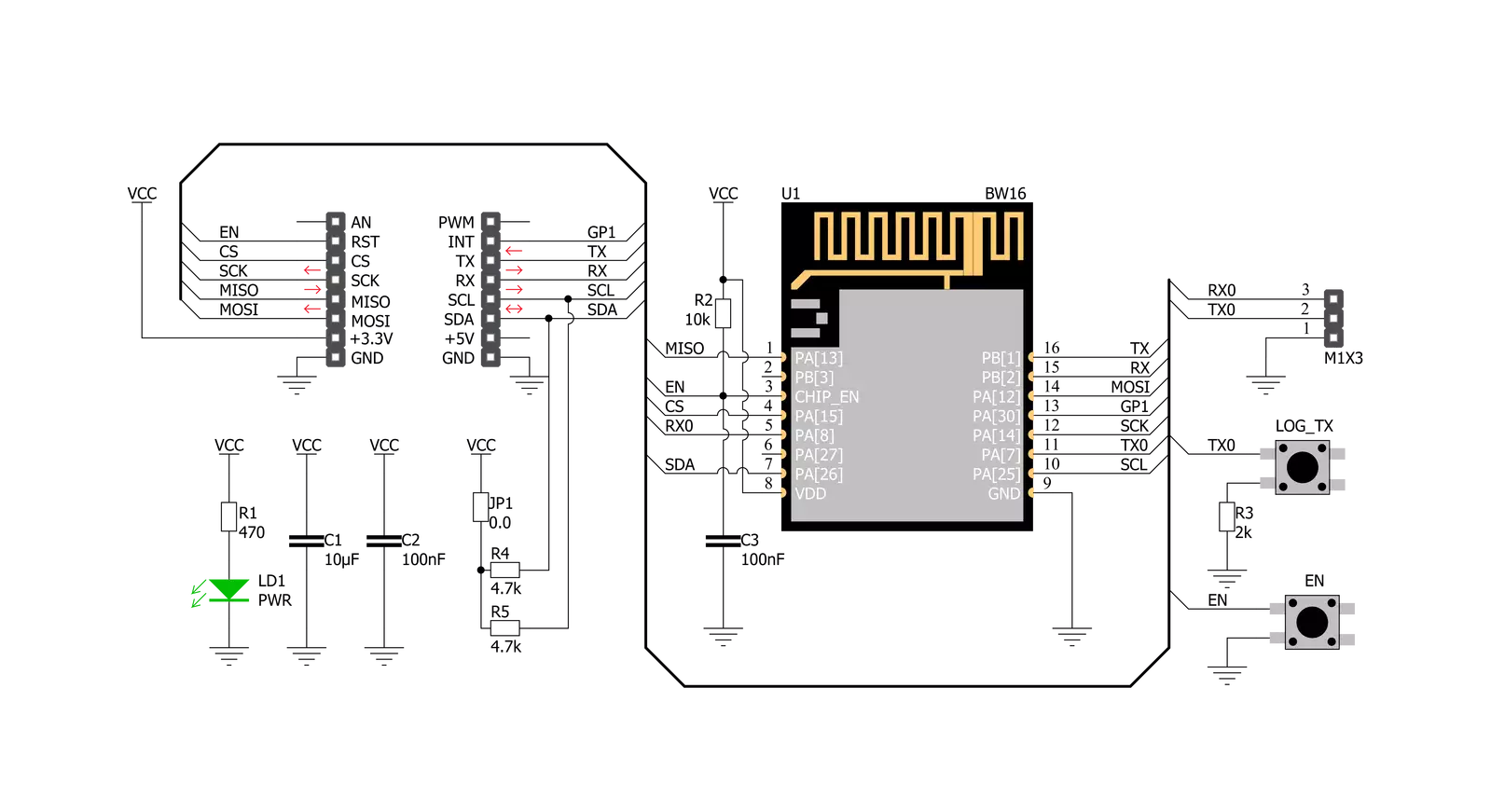
WiFi 11 Click is based on the BW16, a low-power dual-band Wireless LAN (WLAN) and Bluetooth Low Energy SoC module from Ai-Thinker. The BW16 module represents a highly integrated WiFi and Bluetooth SOC based on the RTL8720DN, a highly integrated Single-Chip with a low power dual bands (2.4GHz and 5GHz), Wireless LAN (WLAN), and Bluetooth Low Energy (v5.0). It consists of a high-performance MCU (ARM V8M, Cortex-M4F instruction compatible) named KM4, a low-power MCU (ARM V8M, Cortex-M0 instruction compatible) named KM0, WLAN (802.11 a/b/g/n) MAC, a 1T1R capable WLAN baseband, RF, Bluetooth, and other peripherals. The BW16 integrates internal memories for complete WIFI and BLE 5.0 protocol functions. The
embedded memory configuration also provides simple application developments. WiFi 11 Click communicates with MCU using the UART interface at 57600 bps as its default communication protocol. Still, it also allows the user to use other interfaces, such as SPI and I2C if he wants to configure the module and write the library himself. A jumper JP1 on this Click board™ also enables the necessary pull-up resistors on the SCL and SDA lines of I2C communication. After initializing the primary module and before any program uploading, the user should write network and TCP server parameters. Additional functionality, such as the Chip Enable button labeled as RST, used to Enable or put the module in Shut-Down mode, is provided and routed at the
EN pin of the mikroBUS™ socket. Alongside this pin, this Click board™ has one general purpose pin GP1 routed at the INT pin of the mikroBUS™ socket, which can be used in various cases like interrupt or other purposes. WiFi 11 Click also has an additional header with UART RX0 and TX0 module pins on itself and a button labeled as LOG_TX, which can be used for Firmware Updates or as a low-power mode Wake-Up function. This Click board™ can be operated only with a 3.3V logic voltage level. The board must perform appropriate logic voltage level conversion before using MCUs with different logic levels. Also, it comes equipped with a library containing functions and an example code that can be used, as a reference, for further development.

Features overview
Development board
Nucleo-64 with STM32L073RZ MCU offers a cost-effective and adaptable platform for developers to explore new ideas and prototype their designs. This board harnesses the versatility of the STM32 microcontroller, enabling users to select the optimal balance of performance and power consumption for their projects. It accommodates the STM32 microcontroller in the LQFP64 package and includes essential components such as a user LED, which doubles as an ARDUINO® signal, alongside user and reset push-buttons, and a 32.768kHz crystal oscillator for precise timing operations. Designed with expansion and flexibility in mind, the Nucleo-64 board features an ARDUINO® Uno V3 expansion connector and ST morpho extension pin
headers, granting complete access to the STM32's I/Os for comprehensive project integration. Power supply options are adaptable, supporting ST-LINK USB VBUS or external power sources, ensuring adaptability in various development environments. The board also has an on-board ST-LINK debugger/programmer with USB re-enumeration capability, simplifying the programming and debugging process. Moreover, the board is designed to simplify advanced development with its external SMPS for efficient Vcore logic supply, support for USB Device full speed or USB SNK/UFP full speed, and built-in cryptographic features, enhancing both the power efficiency and security of projects. Additional connectivity is
provided through dedicated connectors for external SMPS experimentation, a USB connector for the ST-LINK, and a MIPI® debug connector, expanding the possibilities for hardware interfacing and experimentation. Developers will find extensive support through comprehensive free software libraries and examples, courtesy of the STM32Cube MCU Package. This, combined with compatibility with a wide array of Integrated Development Environments (IDEs), including IAR Embedded Workbench®, MDK-ARM, and STM32CubeIDE, ensures a smooth and efficient development experience, allowing users to fully leverage the capabilities of the Nucleo-64 board in their projects.

Microcontroller Overview
MCU Card / MCU

Architecture
ARM Cortex-M0
MCU Memory (KB)
192
Silicon Vendor
STMicroelectronics
Pin count
64
RAM (Bytes)
20480
You complete me!
Accessories
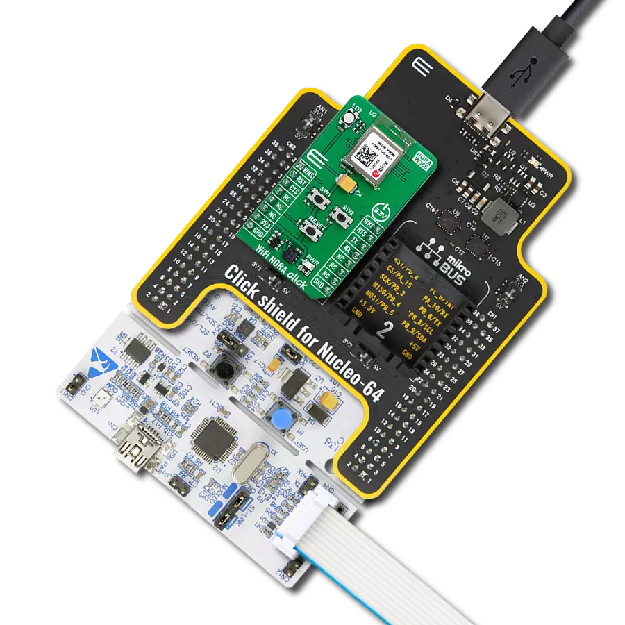
Click Shield for Nucleo-64 comes equipped with two proprietary mikroBUS™ sockets, allowing all the Click board™ devices to be interfaced with the STM32 Nucleo-64 board with no effort. This way, Mikroe allows its users to add any functionality from our ever-growing range of Click boards™, such as WiFi, GSM, GPS, Bluetooth, ZigBee, environmental sensors, LEDs, speech recognition, motor control, movement sensors, and many more. More than 1537 Click boards™, which can be stacked and integrated, are at your disposal. The STM32 Nucleo-64 boards are based on the microcontrollers in 64-pin packages, a 32-bit MCU with an ARM Cortex M4 processor operating at 84MHz, 512Kb Flash, and 96KB SRAM, divided into two regions where the top section represents the ST-Link/V2 debugger and programmer while the bottom section of the board is an actual development board. These boards are controlled and powered conveniently through a USB connection to program and efficiently debug the Nucleo-64 board out of the box, with an additional USB cable connected to the USB mini port on the board. Most of the STM32 microcontroller pins are brought to the IO pins on the left and right edge of the board, which are then connected to two existing mikroBUS™ sockets. This Click Shield also has several switches that perform functions such as selecting the logic levels of analog signals on mikroBUS™ sockets and selecting logic voltage levels of the mikroBUS™ sockets themselves. Besides, the user is offered the possibility of using any Click board™ with the help of existing bidirectional level-shifting voltage translators, regardless of whether the Click board™ operates at a 3.3V or 5V logic voltage level. Once you connect the STM32 Nucleo-64 board with our Click Shield for Nucleo-64, you can access hundreds of Click boards™, working with 3.3V or 5V logic voltage levels.

Used MCU Pins
mikroBUS™ mapper
Take a closer look
Click board™ Schematic
Step by step
Project assembly
Start by selecting your development board and Click board™. Begin with the Nucleo-64 with STM32L073RZ MCU as your development board.


Track your results in real time
Application Output
1. Application Output - In Debug mode, the 'Application Output' window enables real-time data monitoring, offering direct insight into execution results. Ensure proper data display by configuring the environment correctly using the provided tutorial.

2. UART Terminal - Use the UART Terminal to monitor data transmission via a USB to UART converter, allowing direct communication between the Click board™ and your development system. Configure the baud rate and other serial settings according to your project's requirements to ensure proper functionality. For step-by-step setup instructions, refer to the provided tutorial.

3. Plot Output - The Plot feature offers a powerful way to visualize real-time sensor data, enabling trend analysis, debugging, and comparison of multiple data points. To set it up correctly, follow the provided tutorial, which includes a step-by-step example of using the Plot feature to display Click board™ readings. To use the Plot feature in your code, use the function: plot(*insert_graph_name*, variable_name);. This is a general format, and it is up to the user to replace 'insert_graph_name' with the actual graph name and 'variable_name' with the parameter to be displayed.

Software Support
Library Description
This library contains API for WiFi 11 Click driver.
Key functions:
wifi11_send_cmd- Send command functionwifi11_create_tcp_udp_server- Create TCP/UDP server functionwifi11_connect_to_ap- Connect to AP function
Open Source
Code example
The complete application code and a ready-to-use project are available through the NECTO Studio Package Manager for direct installation in the NECTO Studio. The application code can also be found on the MIKROE GitHub account.
/*!
 * \file
 * \brief Wifi11 Click example
 *
 * # Description
 * This example reads and processes data from WiFi 11 Clicks.
 *
 * The demo application is composed of two sections :
 *
 * ## Application Init
 * Initializes the driver and powers up the module, then connects to the desired AP
 * and creates TCP and UDP servers on the desired local port.
 *
 * ## Application Task
 * Logs all the received data and module's responses on the USB UART.
 *
 * ## Additional Function
 * - static void wifi11_clear_app_buf ( void )
 * - static void wifi11_error_check( err_t error_flag )
 * - static void wifi11_log_app_buf ( void )
 * - static err_t wifi11_rsp_check ( void )
 * - static err_t wifi11_process ( void )
 *
 * @note
 * In order for the example to work, user needs to set the AP SSID, password, and Local port
 * on which the TCP and UDP servers will be created.
 * Enter valid data for the following macros: AP_SSID, AP_PASSWORD and LOCAL_PORT.
 *
 * \author MikroE Team
 *
 */
// ------------------------------------------------------------------- INCLUDES

#include "board.h"
#include "log.h"
#include "wifi11.h"
#include "string.h"

#define APP_OK                              0
#define APP_ERROR_DRIVER                    -1
#define APP_ERROR_OVERFLOW                  -2
#define APP_ERROR_TIMEOUT                   -3

#define RSP_OK                              "OK"
#define RSP_ERROR                           "ERROR"

#define AP_SSID                             ""   // Set AP SSID
#define AP_PASSWORD                         ""   // Set AP password - if the AP is OPEN remain this NULL
#define LOCAL_PORT                          1    // Set Local port on which the TCP and UDP servers will be created.

#define PROCESS_BUFFER_SIZE                 500

static wifi11_t wifi11;
static log_t logger;

static char app_buf[ PROCESS_BUFFER_SIZE ]  = { 0 };
static int32_t app_buf_len                  = 0;
static int32_t app_buf_cnt                  = 0;

static err_t app_error_flag;


/**
 * @brief WiFi 11 clearing application buffer.
 * @details This function clears memory of application buffer and reset its length and counter.
 * @note None.
 */
static void wifi11_clear_app_buf ( void );

/**
 * @brief WiFi 11 data reading function.
 * @details This function reads data from device and appends data to application buffer.
 *
 * @return @li @c  0 - Read some data.
 *         @li @c -1 - Nothing is read.
 *         @li @c -2 - Application buffer overflow.
 *
 * See #err_t definition for detailed explanation.
 * @note None.
 */
static err_t wifi11_process ( void );

/**
 * @brief WiFi 11 check for errors.
 * @details This function checks for different types of errors and logs them on UART.
 * @note None.
 */
static void wifi11_error_check( err_t error_flag );

/**
 * @brief WiFi 11 logs application buffer.
 * @details This function logs data from application buffer.
 * @note None.
 */
static void wifi11_log_app_buf ( void );

/**
 * @brief WiFi 11 response check.
 * @details This function checks for response and returns the status of response.
 *
 * @return application status.
 * See #err_t definition for detailed explanation.
 * @note None.
 */
static err_t wifi11_rsp_check ( void );

void application_init ( void )
{
    log_cfg_t log_cfg;
    wifi11_cfg_t cfg;

    /**
     * Logger initialization.
     * Default baud rate: 115200
     * Default log level: LOG_LEVEL_DEBUG
     * @note If USB_UART_RX and USB_UART_TX
     * are defined as HAL_PIN_NC, you will
     * need to define them manually for log to work.
     * See @b LOG_MAP_USB_UART macro definition for detailed explanation.
     */
    LOG_MAP_USB_UART( log_cfg );
    log_init( &logger, &log_cfg );
    log_info( &logger, "---- Application Init ----" );

    //  Click initialization.

    wifi11_cfg_setup( &cfg );
    WIFI11_MAP_MIKROBUS( cfg, MIKROBUS_1 );
    wifi11_init( &wifi11, &cfg );
    Delay_ms ( 100 );

    wifi11_reset_device( &wifi11 );
    Delay_ms ( 1000 );
    Delay_ms ( 1000 );

    // dummy read
    wifi11_process( );
    wifi11_clear_app_buf( );

    log_printf( &logger, "\r\n ---- Common commands ---- \r\n" );
    Delay_ms ( 500 );

    // Test AT command ready
    wifi11_send_cmd( &wifi11, WIFI11_CMD_AT );
    app_error_flag = wifi11_rsp_check( );
    wifi11_error_check( app_error_flag );
    Delay_ms ( 500 );

    // Query version info
    wifi11_send_cmd( &wifi11, WIFI11_CMD_ATSV );
    app_error_flag = wifi11_rsp_check( );
    wifi11_error_check( app_error_flag );
    Delay_ms ( 500 );

    log_printf( &logger, "\r\n ---- WiFi commands ---- \r\n" );
    Delay_ms ( 500 );

    // Set WiFi mode - Station
    wifi11_send_cmd_with_parameter( &wifi11, WIFI11_CMD_ATPW, "1" );
    app_error_flag = wifi11_rsp_check( );
    wifi11_error_check( app_error_flag );
    Delay_ms ( 500 );

    // Connect to AP
    wifi11_connect_to_ap( &wifi11, AP_SSID, AP_PASSWORD );
    app_error_flag = wifi11_rsp_check( );
    wifi11_error_check( app_error_flag );
    Delay_ms ( 500 );

    // Wifi information
    wifi11_send_cmd( &wifi11, WIFI11_CMD_ATW );
    app_error_flag = wifi11_rsp_check( );
    wifi11_error_check( app_error_flag );
    Delay_ms ( 500 );

    log_printf( &logger, "\r\n ---- TCP/IP commands ---- \r\n" );
    Delay_ms ( 500 );

    // Create TCP Server
    wifi11_create_tcp_udp_server( &wifi11, WIFI11_TCP_MODE, LOCAL_PORT );
    app_error_flag = wifi11_rsp_check( );
    wifi11_error_check( app_error_flag );
    Delay_ms ( 500 );

    // Create UDP Server
    wifi11_create_tcp_udp_server( &wifi11, WIFI11_UDP_MODE, LOCAL_PORT );
    app_error_flag = wifi11_rsp_check( );
    wifi11_error_check( app_error_flag );
    Delay_ms ( 500 );

    // Enable auto receive data mode
    wifi11_send_cmd_with_parameter( &wifi11, WIFI11_CMD_ATPK, "1" );
    app_error_flag = wifi11_rsp_check( );
    wifi11_error_check( app_error_flag );
    Delay_ms ( 500 );

    // Check network connection status
    wifi11_send_cmd( &wifi11, WIFI11_CMD_ATPI );
    app_error_flag = wifi11_rsp_check( );
    wifi11_error_check( app_error_flag );
    Delay_ms ( 500 );

    log_printf( &logger, "\r\n ---- Please connect to the TCP/UDP server listed above via" );
    log_printf( &logger, " a TCP/UDP client ---- \r\n" );
}

void application_task ( void )
{
    wifi11_process( );
    wifi11_log_app_buf( );
}

int main ( void )
{
    /* Do not remove this line or clock might not be set correctly. */
    #ifdef PREINIT_SUPPORTED
    preinit();
    #endif

    application_init( );

    for ( ; ; )
    {
        application_task( );
    }

    return 0;
}

static void wifi11_clear_app_buf ( void )
{
    memset( app_buf, 0, app_buf_len );
    app_buf_len = 0;
    app_buf_cnt = 0;
}

static err_t wifi11_process ( void )
{
    err_t return_flag = APP_ERROR_DRIVER;
    int32_t rx_size;
    char rx_buff[ PROCESS_BUFFER_SIZE ] = { 0 };

    rx_size = wifi11_generic_read( &wifi11, rx_buff, PROCESS_BUFFER_SIZE );

    if ( rx_size > 0 )
    {
        int32_t buf_cnt = 0;
        return_flag = APP_OK;

        if ( app_buf_len + rx_size >= PROCESS_BUFFER_SIZE )
        {
            wifi11_clear_app_buf(  );
            return_flag = APP_ERROR_OVERFLOW;
        }
        else
        {
            buf_cnt = app_buf_len;
            app_buf_len += rx_size;
        }

        for ( int32_t rx_cnt = 0; rx_cnt < rx_size; rx_cnt++ )
        {
            if ( rx_buff[ rx_cnt ] != 0 )
            {
                app_buf[ ( buf_cnt + rx_cnt ) ] = rx_buff[ rx_cnt ];
            }
            else
            {
                app_buf_len--;
                buf_cnt--;
            }
        }
    }

    return return_flag;
}

static err_t wifi11_rsp_check ( void )
{
    uint16_t timeout_cnt = 0;
    uint16_t timeout = 10000;

    err_t error_flag = wifi11_process(  );

    if ( ( error_flag != 0 ) && ( error_flag != -1 ) )
    {
        return error_flag;
    }

    while ( ( strstr( app_buf, RSP_OK ) == 0 ) && ( strstr( app_buf, RSP_ERROR ) == 0 ) )
    {
        error_flag = wifi11_process(  );
        if ( ( error_flag != 0 ) && ( error_flag != -1 ) )
        {
            return error_flag;
        }

        timeout_cnt++;
        if ( timeout_cnt > timeout )
        {
            while ( ( strstr( app_buf, RSP_OK ) == 0 ) && ( strstr( app_buf, RSP_ERROR ) == 0 ) )
            {
                wifi11_send_cmd( &wifi11, WIFI11_CMD_AT );
                wifi11_process(  );
                Delay_ms ( 100 );
            }
            wifi11_clear_app_buf(  );
            return APP_ERROR_TIMEOUT;
        }

        Delay_ms ( 1 );
    }

    wifi11_log_app_buf();

    return APP_OK;
}

static void wifi11_error_check( err_t error_flag )
{
    if ( ( error_flag != 0 ) && ( error_flag != -1 ) )
    {
        switch ( error_flag )
        {
            case -2:
                log_error( &logger, " Overflow!" );
                break;
            case -3:
                log_error( &logger, " Timeout!" );
                break;
            default:
                break;
        }
    }
}

static void wifi11_log_app_buf ( void )
{
    for ( int32_t buf_cnt = 0; buf_cnt < app_buf_len; buf_cnt++ )
    {
        log_printf( &logger, "%c", app_buf[ buf_cnt ] );
    }

    wifi11_clear_app_buf(  );
}

// ------------------------------------------------------------------------ END
Additional Support
Resources
Category:WiFi