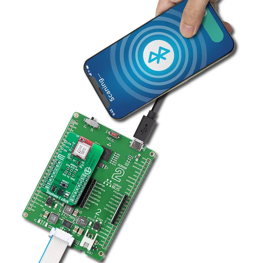
Experience the convenience of wireless networking with ATWINC3400-MR210CA and STM32F091RC
Our WiFi solution, your digital oasis!

Published Feb 26, 2024
Click board™
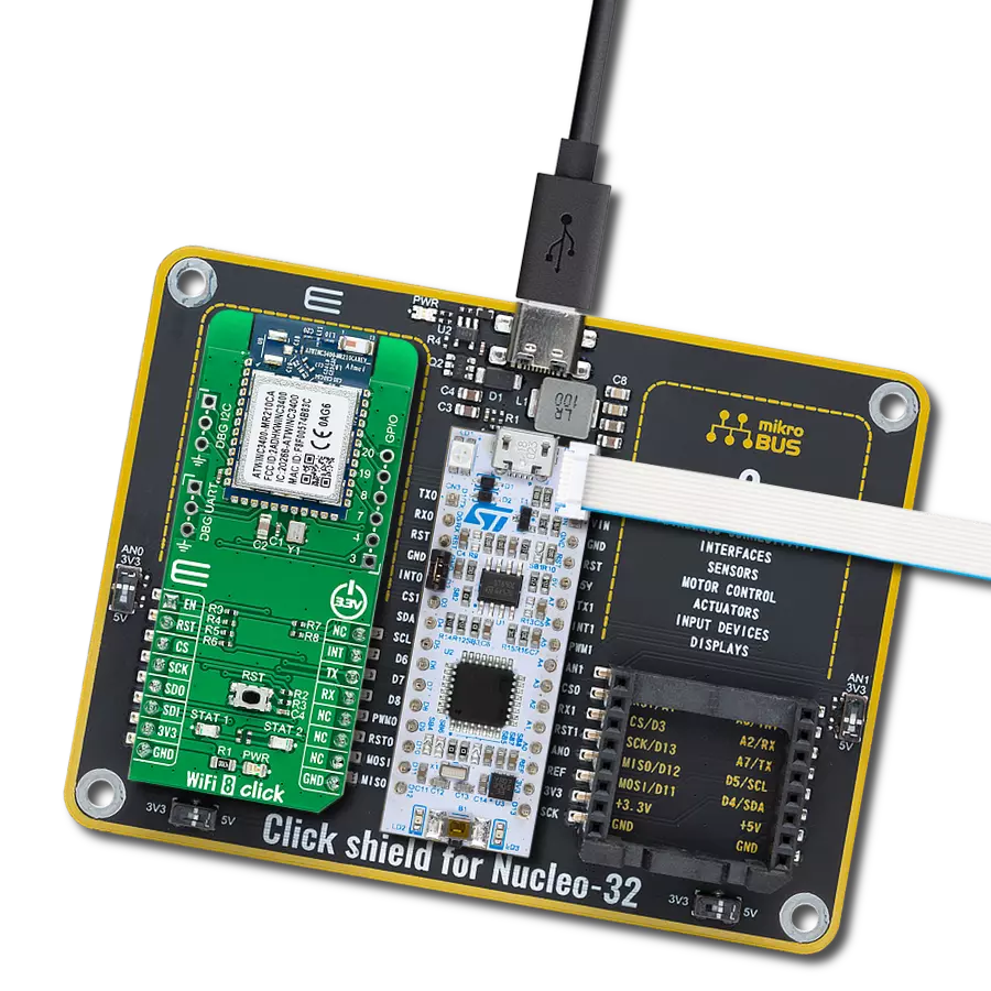
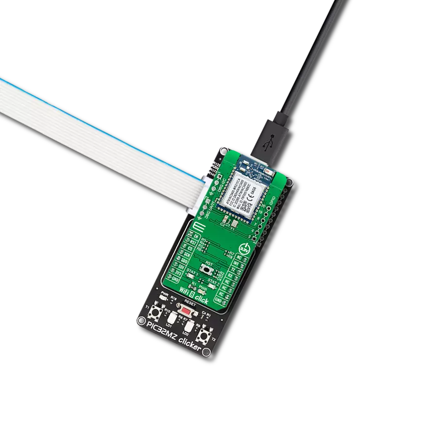
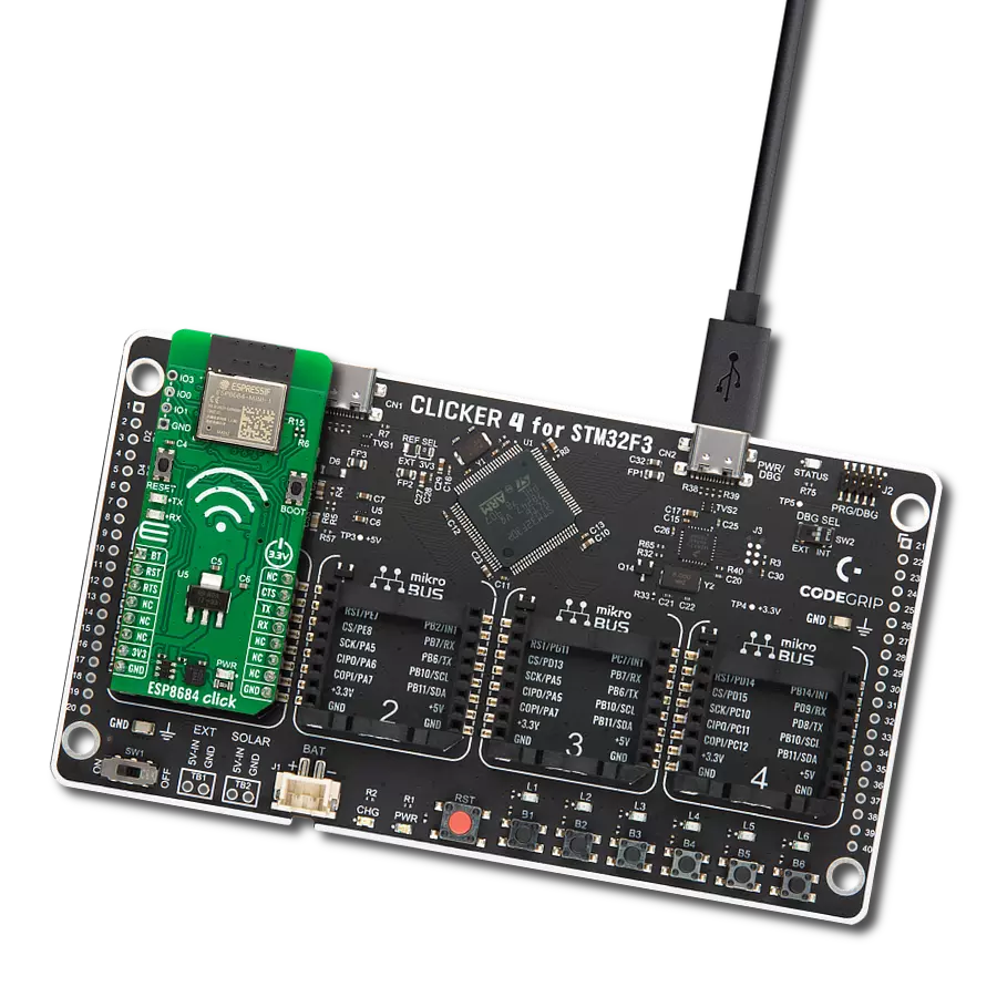
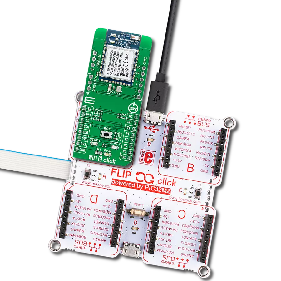
WiFi 8 Click
Dev. board
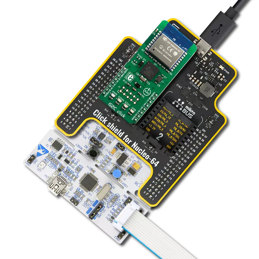
Nucleo-64 with STM32F091RC MCU
Compiler
NECTO Studio
MCU
STM32F091RC
With our WiFi solution, you can enjoy the freedom of an untethered connection, empowering you to work, play, and connect without boundaries
A
A
Hardware Overview
How does it work?
WiFi 8 Click is based on the ATWINC3400-MR210CA, an RF/Baseband/Medium Access Control (MAC) network controller (Bluetooth 5.0 certified module) optimized for low-power and high-performance mobile applications from Microchip Technology. The ATWINC3400-MR210CA supports the simultaneous use of Bluetooth Low Energy and WiFi via a coexistence mechanism, allowing them to share the same radio. The radio defaults to WiFi use until a Bluetooth Low Energy event occurs, in which case the radio is switched over for Bluetooth Low Energy use. It comes with integrated power and low-noise amplifiers, transmit/receive switch (for WiFi and Bluetooth), a power management unit, an integrated 2.4GHz chip antenna, and an additional 32.768 kHz clock to supply the module during Sleep mode. The ATWINC3400-MR210CA module has multiple device states (WiFi TX/RX, BLE TX/RX, Doze, and Power-Down Mode) based on the state of the IEEE 802.11 and Bluetooth subsystems with
the possibility for both subsystems to be active at the same time. It has two Cortus APS3 32-bit processors, one for WiFi and the other for Bluetooth. The APS3 core uses a 256KB instruction/boot ROM, 420KB instruction RAM, and 128KB data RAM. In addition, the module uses a 160KB shared/exchange RAM accessible by the processor and MAC, which allows the processor to perform various data management tasks on the TX and RX data packets. WiFi 8 Click communicates with MCU using the SPI serial interface with a maximum clock frequency of 48MHz applicable to all SPI modes. Additional functionality, such as the Chip Enable, is used to Enable or put the module in Shut-Down mode provided and routed at the EN pin of the mikroBUS™ socket. Alongside this pin, this Click board™ has a Reset button routed to the RST pin on the mikroBUS™ socket, which with a low logic level, puts the module into a Reset state and, with a high level, operates the module normally.
This Click board™ also has several additional headers suitable for debugging using the UART and I2C interfaces labeled DBG UART and DBG I2C. It also has a header marked GPIO with all general-purpose pins from the ATWINC3400-MR210CA module. It should be noted that the GPIO functionality is currently not supported by the ATWINC3400 firmware. Besides, it also has two additional LED indicators, red and yellow LEDs labeled STAT1 and STAT2, which can be used for optional user-configurable visual indication. This Click board™ can be operated only with a 3.3V logic voltage level. The board must perform appropriate logic voltage level conversion before using MCUs with different logic levels. Also, it comes equipped with a library containing functions and an example code that can be used, as a reference, for further development.

Features overview
Development board
Nucleo-64 with STM32F091RC MCU offers a cost-effective and adaptable platform for developers to explore new ideas and prototype their designs. This board harnesses the versatility of the STM32 microcontroller, enabling users to select the optimal balance of performance and power consumption for their projects. It accommodates the STM32 microcontroller in the LQFP64 package and includes essential components such as a user LED, which doubles as an ARDUINO® signal, alongside user and reset push-buttons, and a 32.768kHz crystal oscillator for precise timing operations. Designed with expansion and flexibility in mind, the Nucleo-64 board features an ARDUINO® Uno V3 expansion connector and ST morpho extension pin
headers, granting complete access to the STM32's I/Os for comprehensive project integration. Power supply options are adaptable, supporting ST-LINK USB VBUS or external power sources, ensuring adaptability in various development environments. The board also has an on-board ST-LINK debugger/programmer with USB re-enumeration capability, simplifying the programming and debugging process. Moreover, the board is designed to simplify advanced development with its external SMPS for efficient Vcore logic supply, support for USB Device full speed or USB SNK/UFP full speed, and built-in cryptographic features, enhancing both the power efficiency and security of projects. Additional connectivity is
provided through dedicated connectors for external SMPS experimentation, a USB connector for the ST-LINK, and a MIPI® debug connector, expanding the possibilities for hardware interfacing and experimentation. Developers will find extensive support through comprehensive free software libraries and examples, courtesy of the STM32Cube MCU Package. This, combined with compatibility with a wide array of Integrated Development Environments (IDEs), including IAR Embedded Workbench®, MDK-ARM, and STM32CubeIDE, ensures a smooth and efficient development experience, allowing users to fully leverage the capabilities of the Nucleo-64 board in their projects.

Microcontroller Overview
MCU Card / MCU

Architecture
ARM Cortex-M0
MCU Memory (KB)
256
Silicon Vendor
STMicroelectronics
Pin count
64
RAM (Bytes)
32768
You complete me!
Accessories
Click Shield for Nucleo-64 comes equipped with two proprietary mikroBUS™ sockets, allowing all the Click board™ devices to be interfaced with the STM32 Nucleo-64 board with no effort. This way, Mikroe allows its users to add any functionality from our ever-growing range of Click boards™, such as WiFi, GSM, GPS, Bluetooth, ZigBee, environmental sensors, LEDs, speech recognition, motor control, movement sensors, and many more. More than 1537 Click boards™, which can be stacked and integrated, are at your disposal. The STM32 Nucleo-64 boards are based on the microcontrollers in 64-pin packages, a 32-bit MCU with an ARM Cortex M4 processor operating at 84MHz, 512Kb Flash, and 96KB SRAM, divided into two regions where the top section represents the ST-Link/V2 debugger and programmer while the bottom section of the board is an actual development board. These boards are controlled and powered conveniently through a USB connection to program and efficiently debug the Nucleo-64 board out of the box, with an additional USB cable connected to the USB mini port on the board. Most of the STM32 microcontroller pins are brought to the IO pins on the left and right edge of the board, which are then connected to two existing mikroBUS™ sockets. This Click Shield also has several switches that perform functions such as selecting the logic levels of analog signals on mikroBUS™ sockets and selecting logic voltage levels of the mikroBUS™ sockets themselves. Besides, the user is offered the possibility of using any Click board™ with the help of existing bidirectional level-shifting voltage translators, regardless of whether the Click board™ operates at a 3.3V or 5V logic voltage level. Once you connect the STM32 Nucleo-64 board with our Click Shield for Nucleo-64, you can access hundreds of Click boards™, working with 3.3V or 5V logic voltage levels.

Used MCU Pins
mikroBUS™ mapper
Take a closer look
Click board™ Schematic

Step by step
Project assembly
Start by selecting your development board and Click board™. Begin with the Nucleo-64 with STM32F091RC MCU as your development board.


Software Support
Library Description
This library contains API for WiFi 8 Click driver.
Key functions:
wifi8_init_drv- Synchronous API to initialize the device driverwifi8_connect- Asynchronous Wi-Fi connection functionwifi8_socket_bind- Asynchronous bind function associates the provided address and local port to the socket
Open Source
Code example
The complete application code and a ready-to-use project are available through the NECTO Studio Package Manager for direct installation in the NECTO Studio. The application code can also be found on the MIKROE GitHub account.
/*!
 * @file main.c
 * @brief WiFi8 Click example
 *
 * # Description
 * This application showcases capability of the WiFi 8 Click board.
 * It initializes device, connects to local WiFi. Creates TCP, waits for connection
 * and logs every message it receives for clients when it receives CR or LF flag
 * it returns message back to Client.
 *
 * The demo application is composed of two sections :
 *
 * ## Application Init
 * Initializes Host logger, and communication module and pins.
 * Then resets device and initializes devices firmware. If no error
 * occurred it sets callback functions for WiFi and TCP socket, and checks
 * current firmware version. After firmware is read it connects to local WiFi network
 * set by user. When connected it initializes and creates socket.
 *
 * ## Application Task
 * It loops function for handling events. Should notify and log messages when Client
 * is connected/disconnected to TCP server and returns back when receives CR or LF flag.
 *
 * @note
 * User should set @b MAIN_WLAN_SSID and @b MAIN_WLAN_PSK for connecting to local network.
 * When devices connects to network it will log its IP that user need to connect to.
 * After user connects it should get notification and it can send data to server.
 * Server will return message "WiFi 8 Click" when Client sends CR or LF character in message.
 *
 * @author Luka Filipovic
 *
 */

#include "board.h"
#include "log.h"
#include "wifi8.h"

static wifi8_t wifi8;
static log_t logger;

/** Wi-Fi Settings */
#define MAIN_WLAN_SSID      "MikroE Public"         /**< Destination SSID */
#define MAIN_WLAN_AUTH       M2M_WIFI_SEC_WPA_PSK   /**< Security type */
#define MAIN_WLAN_PSK        "mikroe.guest"         /**< Password for Destination SSID */
#define MAIN_TCP_SERVER_PORT 8080                   /**< TCP Server port for client connection */

typedef struct s_msg_wifi_product
{
    uint8_t name[30];

} t_msg_wifi_product;

static t_msg_wifi_product msg_wifi_product =
{
    .name = "WiFi 8 Click"
};

static uint8_t gau8_socket_test_buffer[1024] = {0};

static int8_t tcp_server_socket = -1;
static int8_t tcp_client_socket = -1;
wifi8_sockaddr_in_t addr;

static uint8_t wifi_connected;

static uint8_t scan_request_index = 0;

static uint8_t num_found_ap = 0;

static void wifi_cb(uint8_t u8_msg_type, void *pv_msg);

static void socket_cb(int8_t sock, uint8_t u8_msg, void *pv_msg);

void application_init(void)
{
    log_cfg_t log_cfg;
    wifi8_cfg_t wifi8_cfg;

    /**
     * Logger initialization.
     * Default baud rate: 115200
     * Default log level: LOG_LEVEL_DEBUG
     * @note If USB_UART_RX and USB_UART_TX
     * are defined as HAL_PIN_NC, you will
     * need to define them manually for log to work.
     * See @b LOG_MAP_USB_UART macro definition for detailed explanation.
     */
    LOG_MAP_USB_UART( log_cfg );
    log_init( &logger, &log_cfg );
    log_info(&logger, " Application Init ");

    Delay_ms ( 1000 );

    wifi8_cfg_setup(&wifi8_cfg);
    WIFI8_MAP_MIKROBUS(wifi8_cfg, MIKROBUS_1);
    err_t init_flag = wifi8_init(&wifi8, &wifi8_cfg);
    if (init_flag == SPI_MASTER_ERROR)
    {
        log_error(&logger, " Application Init Error. ");
        log_info(&logger, " Please, run program again... ");
        for (;;);
    }

    if (WIFI8_OK != wifi8_default_cfg(&wifi8))
    {
        log_error(&logger, " Default configuartion. ");
        for (;;);
    }
    //Set callback functions for WiFi and TCP socket
    wifi8.app_wifi_cb = wifi_cb;
    wifi8.app_socket_cb = socket_cb;
    wifi_connected = M2M_WIFI_DISCONNECTED;

    wifi8_m2m_rev_t fw_version;
    if (WIFI8_OK == wifi8_get_full_firmware_version(&wifi8, &fw_version))
    {
        log_printf(&logger, "Firmware HIF (%u) : %u.%u \n",
                   ((uint16_t)(((fw_version.u16_firmware_hif_info) >> (14)) & (0x3))),
                   ((uint16_t)(((fw_version.u16_firmware_hif_info) >> (8)) & (0x3f))),
                   ((uint16_t)(((fw_version.u16_firmware_hif_info) >> (0)) & (0xff))));
        log_printf(&logger, "Firmware ver   : %u.%u.%u \n",
                   (uint16_t)fw_version.u8_firmware_major,
                   (uint16_t)fw_version.u8_firmware_minor,
                   (uint16_t)fw_version.u8_firmware_patch);
        log_printf(&logger, "Firmware Build %s Time %s\n", fw_version.build_date, fw_version.build_time);
    }
    else
    {
        log_error(&logger, " reading full firmware version ");
        for (;;);
    }

    if (wifi_connected == M2M_WIFI_DISCONNECTED)
    {
        if (WIFI8_OK != wifi8_connect(&wifi8, MAIN_WLAN_SSID, sizeof(MAIN_WLAN_SSID),
                                      MAIN_WLAN_AUTH, MAIN_WLAN_PSK, M2M_WIFI_CH_ALL))
        {
            log_error(&logger, " Connection");
            for (;;);
        }
        else
        {
            log_info(&logger, " Connecting... ");
        }
    }

    while (wifi_connected != M2M_WIFI_CONNECTED)
    {
        wifi8_handle_events(&wifi8);
    }

    wifi8_socket_init(&wifi8);
    addr.sin_family = 2;
    addr.sin_port = (uint16_t)((((uint16_t)((MAIN_TCP_SERVER_PORT))) << 8) | (((uint16_t)((MAIN_TCP_SERVER_PORT))) >> 8));
    addr.sin_addr.s_addr = 0;

    log_info(&logger, " Application Task ");
}

void application_task(void)
{
    wifi8_handle_events(&wifi8);

    if (tcp_server_socket < 0)
    {

        if ((tcp_server_socket = wifi8_socket_create(&wifi8, 2, 1, 0)) < 0)
        {
            log_printf(&logger, "main: failed to create TCP server socket error!\r\n");
        }
        else
        {
            wifi8_socket_bind(&wifi8, tcp_server_socket, (wifi8_sockaddr_t *)&addr,
                              sizeof(wifi8_sockaddr_in_t));
        }
    }
}

int main ( void )
{
    /* Do not remove this line or clock might not be set correctly. */
    #ifdef PREINIT_SUPPORTED
    preinit();
    #endif

    application_init( );

    for ( ; ; )
    {
        application_task( );
    }

    return 0;
}

static void wifi_cb(uint8_t u8_msg_type, void *pv_msg)
{
    switch (u8_msg_type)
    {
        case M2M_WIFI_RESP_SCAN_DONE:
        {
            wifi8_m2m_scan_done_t *pstr_info = (wifi8_m2m_scan_done_t *)pv_msg;
            scan_request_index = 0;
            if (pstr_info->u8_numof_ch >= 1)
            {
                wifi8_req_scan_result(&wifi8, scan_request_index);
                scan_request_index++;
            }
            else
            {
                wifi8_request_scan(&wifi8, M2M_WIFI_CH_ALL);
            }

            break;
        }
        case M2M_WIFI_RESP_SCAN_RESULT:
        {
            wifi8_m2m_wifiscan_result_t *pstr_scan_result = (wifi8_m2m_wifiscan_result_t *)pv_msg;
            uint16_t demo_ssid_len;
            uint16_t scan_ssid_len = strlen((char *)pstr_scan_result->au8ssid);

            log_printf(&logger, "wifi_cb: [%d] SSID:%s\r\n", (uint16_t)scan_request_index, pstr_scan_result->au8ssid);

            num_found_ap = wifi8.ch_num;
            if (scan_ssid_len)
            {
                demo_ssid_len = strlen((const char *)MAIN_WLAN_SSID);
                if ((demo_ssid_len == scan_ssid_len) &&
                    (!memcmp(pstr_scan_result->au8ssid, (uint8_t *)MAIN_WLAN_SSID, demo_ssid_len)))
                {
                    log_printf(&logger, "wifi_cb: found %s \r\n", MAIN_WLAN_SSID);
                    wifi8_connect(&wifi8, MAIN_WLAN_SSID, sizeof(MAIN_WLAN_SSID),
                                M2M_WIFI_SEC_WPA_PSK, MAIN_WLAN_PSK, M2M_WIFI_CH_ALL);
                    break;
                }
            }

            if (scan_request_index < num_found_ap)
            {
                wifi8_req_scan_result(&wifi8, scan_request_index);
                scan_request_index++;
            }
            else
            {
                log_printf(&logger, "wifi_cb: can not find AP %s\r\n", MAIN_WLAN_SSID);
                wifi8_request_scan(&wifi8, M2M_WIFI_CH_ALL);
            }

            break;
        }
        case M2M_WIFI_RESP_CON_STATE_CHANGED:
        {
            wifi8_m2m_wifi_state_changed_t *pstr_wifi_state = (wifi8_m2m_wifi_state_changed_t *)pv_msg;
            if (pstr_wifi_state->u8_curr_state == M2M_WIFI_CONNECTED)
            {
                log_printf(&logger, "wifi_cb: connected\r\n");
            }
            else if (pstr_wifi_state->u8_curr_state == M2M_WIFI_DISCONNECTED)
            {
                log_printf(&logger, "wifi_cb: disconnected\r\n");
                wifi_connected = M2M_WIFI_DISCONNECTED;

                wifi8_request_scan(&wifi8, M2M_WIFI_CH_ALL);
            }

            break;
        }
        case M2M_WIFI_REQ_DHCP_CONF:
        {
            volatile uint8_t *pu8ip_address = (uint8_t *)pv_msg;

            log_printf(&logger, "wifi_cb: IP: %u.%u.%u.%u\r\n",
                    (uint16_t)pu8ip_address[0], (uint16_t)pu8ip_address[1],
                    (uint16_t)pu8ip_address[2], (uint16_t)pu8ip_address[3]);

            wifi_connected = M2M_WIFI_CONNECTED;
            break;
        }
        default:
        {
            break;
        }
    }
}

static void socket_cb(int8_t sock, uint8_t u8_msg, void *pv_msg)
{
    switch (u8_msg)
    {
        case SOCKET_MSG_BIND:
        {
            wifi8_socket_bind_msg_t *pstr_bind = (wifi8_socket_bind_msg_t *)pv_msg;
            if (pstr_bind && pstr_bind->status == 0)
            {
                log_printf(&logger, "socket_cb: bind success!\r\n");
                Delay_ms ( 500 );
                wifi8_socket_listen(&wifi8, tcp_server_socket, 0);
            }
            else
            {
                log_printf(&logger, "socket_cb: bind error!\r\n");
                wifi8_socket_close(&wifi8, tcp_server_socket);
                tcp_server_socket = -1;
            }
        }
        break;
        case SOCKET_MSG_LISTEN:
        {
            wifi8_socket_listen_msg_t *pstr_listen = (wifi8_socket_listen_msg_t *)pv_msg;
            if (pstr_listen && pstr_listen->status == 0)
            {
                log_printf(&logger, "socket_cb: listen success!\r\n");
            }
            else
            {
                log_printf(&logger, "socket_cb: listen error!\r\n");
                wifi8_socket_close(&wifi8, tcp_server_socket);
                tcp_server_socket = -1;
            }
        }
        break;
        case SOCKET_MSG_ACCEPT:
        {
            wifi8_socket_accept_msg_t *pstr_accept = (wifi8_socket_accept_msg_t *)pv_msg;
            if (pstr_accept)
            {
                log_printf(&logger, "socket_cb: accept success!\r\n");
                tcp_client_socket = pstr_accept->sock;
                wifi8_socket_receive(&wifi8, tcp_client_socket, gau8_socket_test_buffer, sizeof(gau8_socket_test_buffer), 0);
            }
            else
            {
                log_printf(&logger, "socket_cb: accept error!\r\n");
                wifi8_socket_close(&wifi8, tcp_server_socket);
                tcp_server_socket = -1;
            }
        }
        break;
        case SOCKET_MSG_SEND:
        {
            log_printf(&logger, "socket_cb: send success!\r\n");
            wifi8_socket_receive(&wifi8, tcp_client_socket, gau8_socket_test_buffer, sizeof(gau8_socket_test_buffer), 0);
        }
        break;
        case SOCKET_MSG_RECV:
        {
            wifi8_socket_recv_msg_t *pstr_recv = (wifi8_socket_recv_msg_t *)pv_msg;
            if (pstr_recv && pstr_recv->s16_buffer_size > 0)
            {
                log_printf(&logger, "%s", pstr_recv->pu8_buffer);
                if ((strchr(pstr_recv->pu8_buffer, 13) != 0) || (strchr(pstr_recv->pu8_buffer, 10) != 0))
                {
                    wifi8_socket_send(&wifi8, tcp_client_socket, &msg_wifi_product, sizeof(t_msg_wifi_product));
                }
                else
                {
                    wifi8_socket_receive(&wifi8, tcp_client_socket, gau8_socket_test_buffer, sizeof(gau8_socket_test_buffer), 0);
                }
                memset(pstr_recv->pu8_buffer, 0, pstr_recv->s16_buffer_size);
            }
            else
            {
                log_printf(&logger, "socket_cb: close socket!\r\n");
                wifi8_socket_close(&wifi8, tcp_server_socket);
                tcp_server_socket = -1;
            }
        }
        break;
        default:
        {
            break;
        }
    }
}

// ------------------------------------------------------------------------ END
Additional Support
Resources
Category:WiFi