Integrate the Wirepas Mesh wireless connectivity stack into your applications using WIRL-PRO2 and STM32F410RB
Wirepas Click clicks into action!

Published Oct 08, 2024
Click board™
Wirepas Click
Dev. board
Nucleo 64 with STM32F410RB MCU
Compiler
NECTO Studio
MCU
STM32F410RB
Your gateway to creating robust, self-healing, and energy-efficient mesh networks for applications like smart lighting, asset tracking, and more!
A
A
Hardware Overview
How does it work?
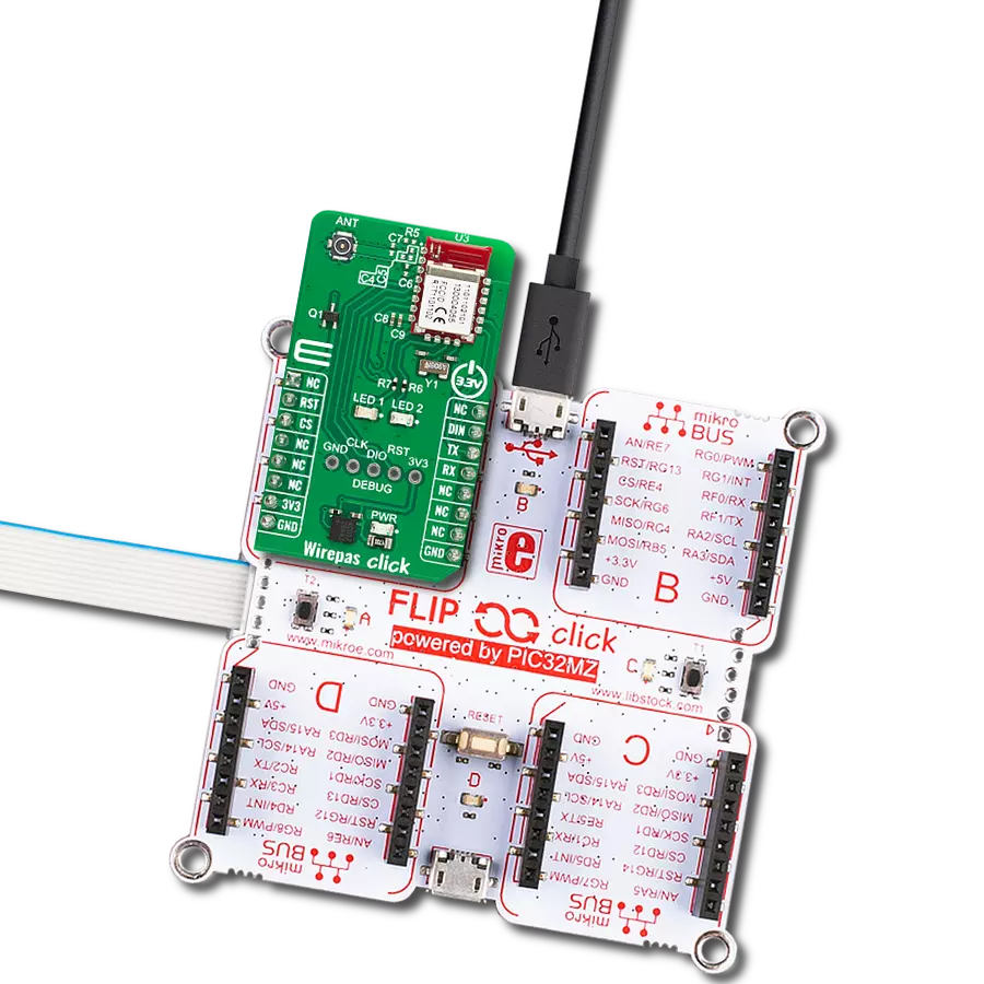
Wirepas Click is based on the WIRL-PRO2 Thetis-I, a radio module with Wirepas Mesh Protocol from Würth Elektronik. The module is meant to be integrated into Wirepas-based routing networks for wireless communication between devices or nodes. The module transmits data securely and reliably in the license-free 2.4 GHz band, which is globally available and features both authentication and encryption mechanisms. The WIRL-PRO2 Thetis-I module features small dimensions comparable to a nano-SIM card (8 mm x 12 mm), including an onboard PCB antenna, making the modules ideal for small-form-factor design. The module works in a frequency range of 2402 up to 2480MHz with a data rate of up to
1Mbps. It is based on nRF52840, a 32-bit ARM Cortex-M4 microcontroller from Nordic Semiconductor. It is accompanied by 1MB of Flash and 256KB of RAM. It has a printed antenna with a smart antenna configuration (2-in-1 module), which allows up to +6dBm of transmit power and -92dBm sensitivity. The connectivity can be even better with an external one attached to the onboard N.FL connector from a vast MIKROE offer. Wirepas Click can work as a beacon because of its very small power consumption. For this purpose, it is equipped with a backup battery. In addition, there are two user-configurable indication LEDs, LED1 and LED2 (blue and green). In addition, the Wirepas Click is also equipped with an
unpopulated header for debugging purposes, which allows you direct communication to the Wirepas microcontroller. Wirepas Click uses a standard 2-wire UART interface to communicate with the host MCU, supporting 115200bps of bitrate. You can reset the device over the RST pin. There is the DIN pin to observe the data flow, which is a data indication to the host MCU with an active Low logic state. This Click board™ can be operated only with a 3.3V logic voltage level. The board must perform appropriate logic voltage level conversion before using MCUs with different logic levels. Also, it comes equipped with a library containing functions and an example code that can be used for further development.

Features overview
Development board
Nucleo-64 with STM32F410RB MCU offers a cost-effective and adaptable platform for developers to explore new ideas and prototype their designs. This board harnesses the versatility of the STM32 microcontroller, enabling users to select the optimal balance of performance and power consumption for their projects. It accommodates the STM32 microcontroller in the LQFP64 package and includes essential components such as a user LED, which doubles as an ARDUINO® signal, alongside user and reset push-buttons, and a 32.768kHz crystal oscillator for precise timing operations. Designed with expansion and flexibility in mind, the Nucleo-64 board features an ARDUINO® Uno V3 expansion connector and ST morpho extension pin
headers, granting complete access to the STM32's I/Os for comprehensive project integration. Power supply options are adaptable, supporting ST-LINK USB VBUS or external power sources, ensuring adaptability in various development environments. The board also has an on-board ST-LINK debugger/programmer with USB re-enumeration capability, simplifying the programming and debugging process. Moreover, the board is designed to simplify advanced development with its external SMPS for efficient Vcore logic supply, support for USB Device full speed or USB SNK/UFP full speed, and built-in cryptographic features, enhancing both the power efficiency and security of projects. Additional connectivity is
provided through dedicated connectors for external SMPS experimentation, a USB connector for the ST-LINK, and a MIPI® debug connector, expanding the possibilities for hardware interfacing and experimentation. Developers will find extensive support through comprehensive free software libraries and examples, courtesy of the STM32Cube MCU Package. This, combined with compatibility with a wide array of Integrated Development Environments (IDEs), including IAR Embedded Workbench®, MDK-ARM, and STM32CubeIDE, ensures a smooth and efficient development experience, allowing users to fully leverage the capabilities of the Nucleo-64 board in their projects.

Microcontroller Overview
MCU Card / MCU

Architecture
ARM Cortex-M4
MCU Memory (KB)
128
Silicon Vendor
STMicroelectronics
Pin count
64
RAM (Bytes)
32768
You complete me!
Accessories
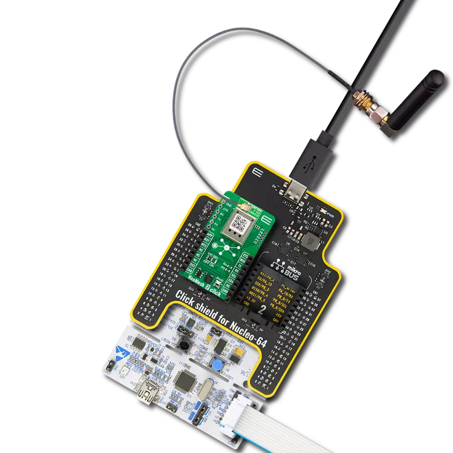
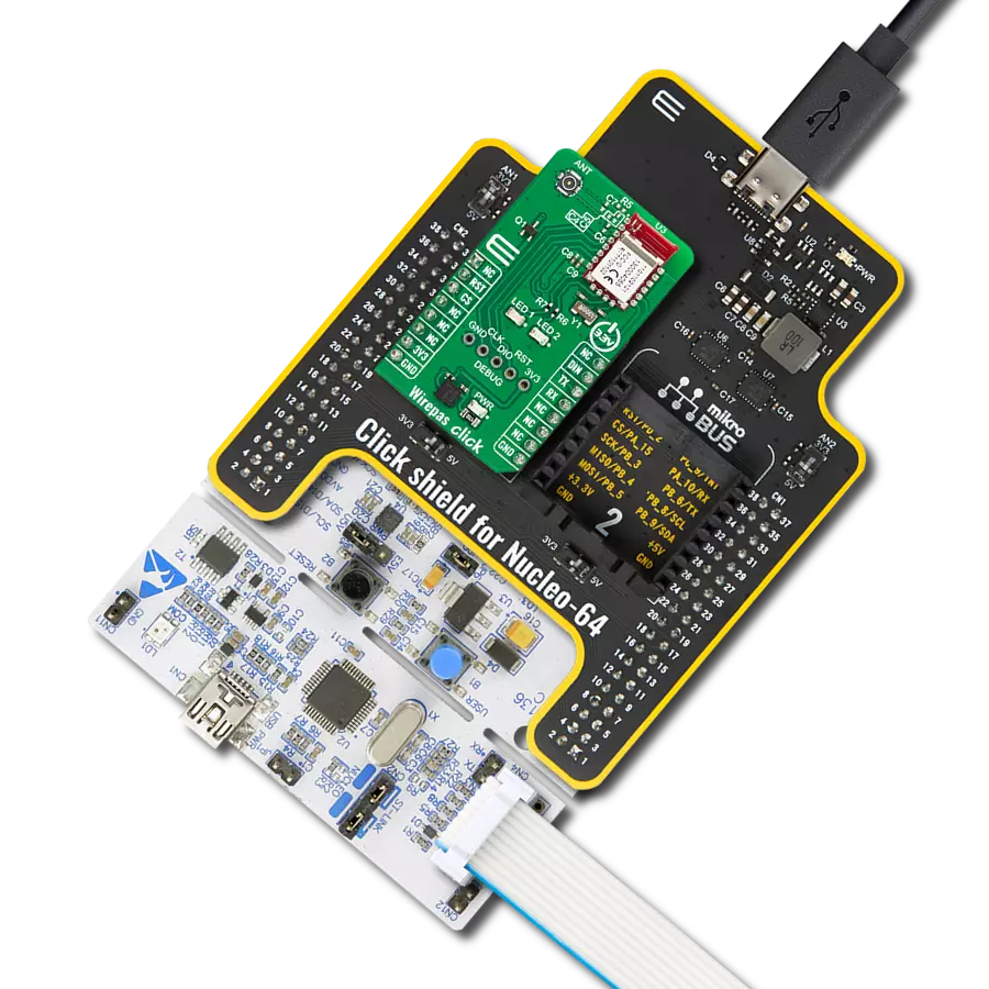
Click Shield for Nucleo-64 comes equipped with two proprietary mikroBUS™ sockets, allowing all the Click board™ devices to be interfaced with the STM32 Nucleo-64 board with no effort. This way, Mikroe allows its users to add any functionality from our ever-growing range of Click boards™, such as WiFi, GSM, GPS, Bluetooth, ZigBee, environmental sensors, LEDs, speech recognition, motor control, movement sensors, and many more. More than 1537 Click boards™, which can be stacked and integrated, are at your disposal. The STM32 Nucleo-64 boards are based on the microcontrollers in 64-pin packages, a 32-bit MCU with an ARM Cortex M4 processor operating at 84MHz, 512Kb Flash, and 96KB SRAM, divided into two regions where the top section represents the ST-Link/V2 debugger and programmer while the bottom section of the board is an actual development board. These boards are controlled and powered conveniently through a USB connection to program and efficiently debug the Nucleo-64 board out of the box, with an additional USB cable connected to the USB mini port on the board. Most of the STM32 microcontroller pins are brought to the IO pins on the left and right edge of the board, which are then connected to two existing mikroBUS™ sockets. This Click Shield also has several switches that perform functions such as selecting the logic levels of analog signals on mikroBUS™ sockets and selecting logic voltage levels of the mikroBUS™ sockets themselves. Besides, the user is offered the possibility of using any Click board™ with the help of existing bidirectional level-shifting voltage translators, regardless of whether the Click board™ operates at a 3.3V or 5V logic voltage level. Once you connect the STM32 Nucleo-64 board with our Click Shield for Nucleo-64, you can access hundreds of Click boards™, working with 3.3V or 5V logic voltage levels.

Used MCU Pins
mikroBUS™ mapper
Take a closer look
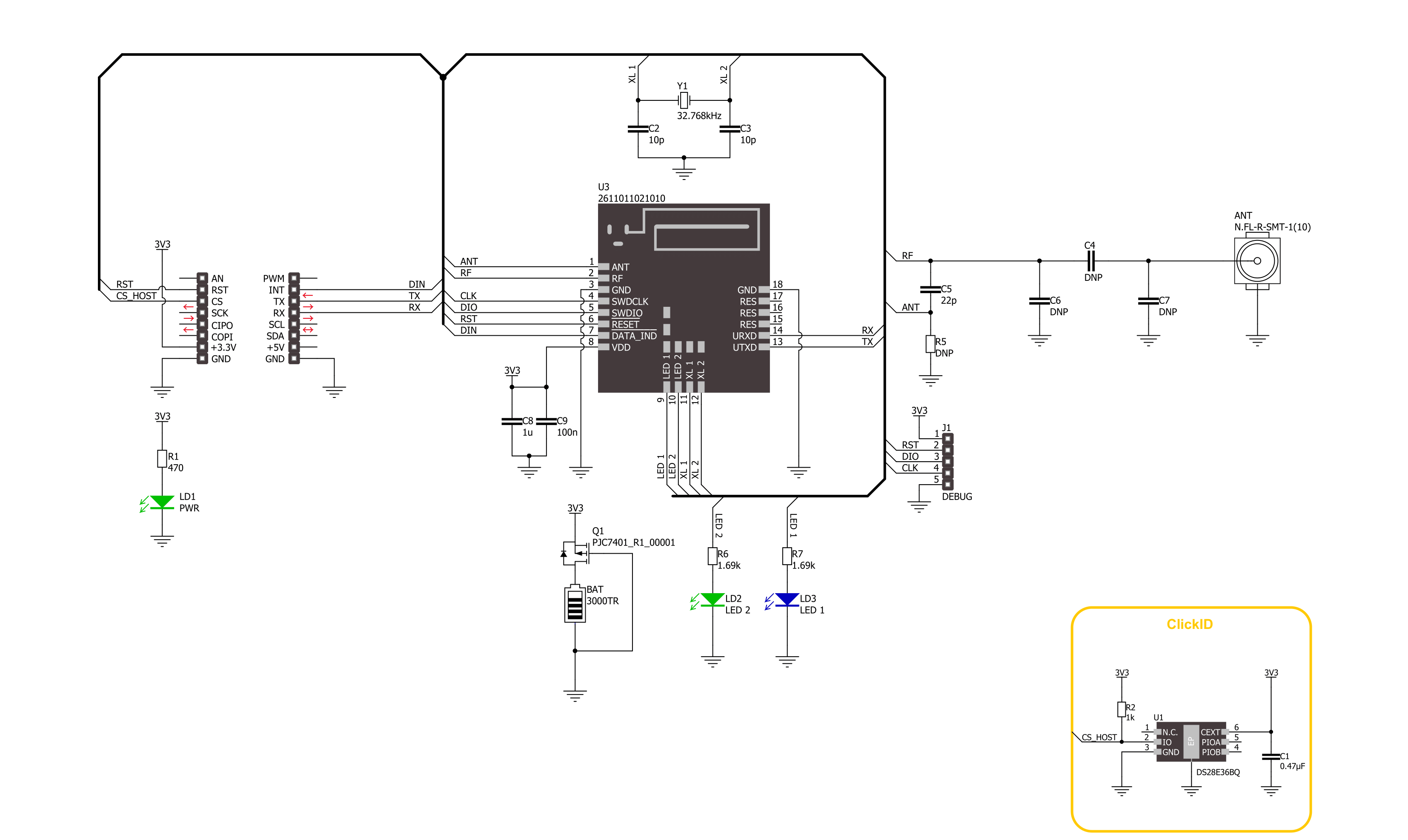
Click board™ Schematic
Step by step
Project assembly
Start by selecting your development board and Click board™. Begin with the Nucleo 64 with STM32F410RB MCU as your development board.


Software Support
Library Description
This library contains API for Wirepas Click driver.
Key functions:
wirepas_send_command- Wirepas send command function.wirepas_write_csap_attribute- Wirepas write CSAP attribute function.wirepas_send_data- Wirepas send data function.
Open Source
Code example
The complete application code and a ready-to-use project are available through the NECTO Studio Package Manager for direct installation in the NECTO Studio. The application code can also be found on the MIKROE GitHub account.
/*!
 * @file main.c
 * @brief Wirepas Click Example.
 *
 * # Description
 * This example demonstrates the use of Wirepas Click board by processing
 * the incoming data and displaying them on the USB UART in sink mode, and sending data to
 * the sinks in router mode.
 *
 * The demo application is composed of two sections :
 *
 * ## Application Init
 * Initializes the driver and performs the Click default configuration, setting device mode, node,
 * net and channel addresses, and starting stack.
 *
 * ## Application Task
 * Router mode - Sending data to the sinks at the same network.
 * Sink mode - Reads and processes all incoming data and displays them on the USB UART.
 *
 * ## Additional Function
 * - err_t wirepas_wait_response ( wirepas_t *ctx, uint8_t primitive_id )
 * - err_t wirepas_parse_frame ( wirepas_t *ctx, uint8_t primitive_id )
 * - err_t wirepas_poll_indication ( wirepas_t *ctx )
 *
 * @note
 * For the best experience use two Clicks in sink mode and one in router.
 *
 * @author Stefan Ilic
 *
 */

#include "board.h"
#include "log.h"
#include "wirepas.h"

#define PROCESS_BUFFER_SIZE 300
#define TX_DATA             "Wirepas Click"

#define MULTI_SINK_MODE     // Comment out this macro to place device into single sink mode.

/**
* @brief Wirepas node addresses.
 * @details Specified setting for node addresses of Wirepas Click driver.
 */
#define ROUTER_NODE_ADDRESS         0x01
#define SINK_1_NODE_ADDRESS         0x02
#define SINK_2_NODE_ADDRESS         0x03
#define NET_ADDRESS                 0x01
#define CHANNEL_ADDRESS             0x01

#define NODE_ADDRESS                ROUTER_NODE_ADDRESS    /* Change the value of this macro to change
                                                              node address, each node should have a unique address */

static wirepas_t wirepas;
static log_t logger;
uint8_t frame_id = 0;
uint8_t stack_auto_start = 1;
uint8_t pdu_capacity = 0x10;
wirepas_sink_data sink_1;
wirepas_sink_data sink_2;

/**
 * @brief Wirepas wait response function.
 * @details This function is used to get response from the device.
 * @param[in] ctx : Click context object.
 * See #wirepas_t object definition for detailed explanation.
 * @param[in] primitive_id : Expected Primitive ID.
 * @return @li @c >=0 - Success,
 *         @li @c  <0 - Error.
 * See #err_t definition for detailed explanation.
 * @note None.
 */
err_t wirepas_wait_response ( wirepas_t *ctx, uint8_t primitive_id );

/**
 * @brief Wirepas parse frame function.
 * @details This function is used to parse frame response from the device.
 * @param[in] ctx : Click context object.
 * See #wirepas_t object definition for detailed explanation.
 * @param[in] primitive_id : Expected Primitive ID.
 * @return @li @c >=0 - Success,
 *         @li @c  <0 - Error.
 * See #err_t definition for detailed explanation.
 * @note None.
 */
err_t wirepas_parse_frame ( wirepas_t *ctx, uint8_t primitive_id );

/**
 * @brief Wirepas send poll indication function function.
 * @details This function is used to send poll indication,
 * and get response from the device.
 * @param[in] ctx : Click context object.
 * See #wirepas_t object definition for detailed explanation.
 * @param[in] primitive_id : Expected Primitive ID.
 * @return @li @c >=0 - Success,
 *         @li @c  <0 - Error.
 * See #err_t definition for detailed explanation.
 * @note None.
 */
err_t wirepas_poll_indication ( wirepas_t *ctx );

void application_init ( void )
{
    log_cfg_t log_cfg;  /**< Logger config object. */
    wirepas_cfg_t wirepas_cfg;  /**< Click config object. */

    /**
     * Logger initialization.
     * Default baud rate: 115200
     * Default log level: LOG_LEVEL_DEBUG
     * @note If USB_UART_RX and USB_UART_TX
     * are defined as HAL_PIN_NC, you will
     * need to define them manually for log to work.
     * See @b LOG_MAP_USB_UART macro definition for detailed explanation.
     */
    LOG_MAP_USB_UART( log_cfg );
    log_init( &logger, &log_cfg );
    log_info( &logger, " Application Init " );

    // Click initialization.
    wirepas_cfg_setup( &wirepas_cfg );
    WIREPAS_MAP_MIKROBUS( wirepas_cfg, MIKROBUS_1 );
    if ( UART_ERROR == wirepas_init( &wirepas, &wirepas_cfg ) )
    {
        log_error( &logger, " Communication init." );
        for ( ; ; );
    }

    wirepas_default_cfg ( &wirepas );

    wirepas.tx_frame_id = 0;
    do
    {
        log_printf( &logger, " Wirepas stack stop request:" );
        wirepas_send_command( &wirepas, WIREPAS_MSAP_STACK_STOP_REQUEST, 0, NULL );
    }
    while ( WIREPAS_OK != wirepas_wait_response ( &wirepas, WIREPAS_MSAP_STACK_STOP_CONFIRM ) );
    Delay_ms ( 1000 );

    do
    {
        log_printf( &logger, " Wirepas factory reset request:" );
        wirepas_send_command( &wirepas, WIREPAS_CSAP_FACTORY_RESET_REQUEST,
                              strlen( WIREPAS_FACTORY_RESET_CODE ), WIREPAS_FACTORY_RESET_CODE );
    }
    while ( WIREPAS_OK != wirepas_wait_response ( &wirepas, WIREPAS_CSAP_FACTORY_RESET_CONFIRM ) );
    Delay_ms ( 1000 );
    Delay_ms ( 1000 );
    Delay_ms ( 1000 );

    do
    {
        log_printf( &logger, " Set node address:" );
        wirepas_set_node_address( &wirepas, NODE_ADDRESS );
    }
    while ( WIREPAS_OK != wirepas_wait_response ( &wirepas, WIREPAS_CSAP_ATTRIBUTE_WRITE_CONFIRM ) );
    Delay_ms ( 1000 );

    do
    {
        log_printf( &logger, " Set net address:" );
        wirepas_set_net_address( &wirepas, NET_ADDRESS );
    }
    while ( WIREPAS_OK != wirepas_wait_response ( &wirepas, WIREPAS_CSAP_ATTRIBUTE_WRITE_CONFIRM ) );
    Delay_ms ( 1000 );

    uint8_t channel_net = CHANNEL_ADDRESS;
    do
    {
        log_printf( &logger, " Set channel address:" );
        wirepas_write_csap_attribute( &wirepas, WIREPAS_CSAP_ATTRIBUTE_NETWORK_CHANNEL, 1, &channel_net );
    }
    while ( WIREPAS_OK != wirepas_wait_response ( &wirepas, WIREPAS_CSAP_ATTRIBUTE_WRITE_CONFIRM ) );
    Delay_ms ( 1000 );


    uint8_t role;
#if ( ROUTER_NODE_ADDRESS == NODE_ADDRESS )
    role = WIREPAS_ROUTER_NODE_MODE;
#else
    role = WIREPAS_SINK_NODE_MODE;
#endif
    do
    {
        log_printf( &logger, " Set role:" );
        wirepas_write_csap_attribute( &wirepas, WIREPAS_CSAP_ATTRIBUTE_NODE_ROLE, 1, &role );
    }
    while ( WIREPAS_OK != wirepas_wait_response ( &wirepas, WIREPAS_CSAP_ATTRIBUTE_WRITE_CONFIRM ) );
    Delay_1sec( );

    do
    {
        log_printf( &logger, " Wirepas Stack start request:" );
        wirepas_send_command( &wirepas, WIREPAS_MSAP_STACK_START_REQUEST, 1, &stack_auto_start );
    }
    while ( WIREPAS_OK != wirepas_wait_response ( &wirepas, WIREPAS_MSAP_STACK_START_CONFIRM ) );
    Delay_1sec( );

#if ( ROUTER_NODE_ADDRESS == NODE_ADDRESS )

    sink_1.pduid = 0x00;
    sink_1.source_endpoint = 0x01;
    sink_1.destination_addr = SINK_1_NODE_ADDRESS;
    sink_1.destination_endpoint = 0x01;
    #if defined MULTI_SINK_MODE
        sink_2.pduid = 0x00;
        sink_2.source_endpoint = 0x01;
        sink_2.destination_addr = SINK_2_NODE_ADDRESS;
        sink_2.destination_endpoint = 0x01;
    #endif
#endif
    Delay_ms ( 100 );

    log_info( &logger, " Application Task " );
}

void application_task ( void )
{
    wirepas_poll_indication ( &wirepas );
#if ( ROUTER_NODE_ADDRESS == NODE_ADDRESS )
    if ( wirepas_get_din_state ( &wirepas ) && ( pdu_capacity > 0 ) )
    {
        log_printf( &logger, " Sending data to the first Sink node: \n" );
        wirepas_send_data ( &wirepas,  sink_1, 0x01, strlen( TX_DATA ), TX_DATA );
        wirepas_wait_response ( &wirepas, WIREPAS_DSAP_DATA_TX_CONFIRM );
        Delay_ms ( 1000 );

        #if defined MULTI_SINK_MODE
            log_printf( &logger, " Sending data to the second Sink node: \n" );
            wirepas_send_data ( &wirepas,  sink_2, 0x01, strlen( TX_DATA ), TX_DATA );
            wirepas_wait_response ( &wirepas, WIREPAS_DSAP_DATA_TX_CONFIRM );
            Delay_ms ( 1000 );
        #endif
    }
#endif
}

int main ( void )
{
    /* Do not remove this line or clock might not be set correctly. */
    #ifdef PREINIT_SUPPORTED
    preinit();
    #endif

    application_init( );

    for ( ; ; )
    {
        application_task( );
    }

    return 0;
}

err_t wirepas_wait_response ( wirepas_t *ctx, uint8_t primitive_id )
{
    for ( uint8_t cnt = 0; cnt < 5; cnt++ )
    {
        if ( WIREPAS_OK == wirepas_parse_frame ( ctx, primitive_id ) )
        {
            return WIREPAS_OK;
        }
    }
    return WIREPAS_ERROR;
}

err_t wirepas_parse_frame ( wirepas_t *ctx, uint8_t primitive_id )
{
    err_t error_flag = wirepas_read_frame ( ctx, &ctx->frame );
    if ( WIREPAS_OK == error_flag )
    {
        if ( ( primitive_id != ctx->frame.primitive_id ) && ( 0 != primitive_id ) )
        {
            error_flag |= WIREPAS_ERROR;
        }
        switch ( ctx->frame.primitive_id )
        {
            case WIREPAS_MSAP_STACK_STOP_CONFIRM:
            case WIREPAS_MSAP_STACK_START_CONFIRM:
            case WIREPAS_CSAP_FACTORY_RESET_CONFIRM:
            case WIREPAS_CSAP_ATTRIBUTE_WRITE_CONFIRM:
            {
                if ( 0 == ctx->frame.payload[ 0 ] )
                {
                    log_printf( &logger, " OK\r\n" );
                }
                else
                {
                    log_printf( &logger, " ERROR[%u]\r\n", ( uint16_t ) ctx->frame.payload[ 0 ] );
                    error_flag |= WIREPAS_ERROR;
                }
                break;
            }
            case WIREPAS_DSAP_DATA_TX_CONFIRM:
            {
                pdu_capacity = ctx->frame.payload[ 3 ];
                if ( 0 == ctx->frame.payload[ 2 ] )
                {
                    log_printf( &logger, " TX request with PDU_ID[%u] is placed\r\n",
                                ( ( ( uint16_t ) ctx->frame.payload[ 1 ] << 8 ) | ctx->frame.payload[ 0 ] ) );
                    sink_1.pduid += 1;
                    if ( sink_1.pduid >= 16 )
                    {
                        sink_1.pduid = 0;
                    }
                #if defined MULTI_SINK_MODE
                    sink_2.pduid += 1;
                    if ( sink_2.pduid >= 16 )
                    {
                        sink_2.pduid = 0;
                    }
                #endif
                }
                else
                {
                    log_printf( &logger, " ERROR[%u] on TX request with PDU_ID[%u]\r\n", ( uint16_t ) ctx->frame.payload[ 2 ],
                                ( ( ( uint16_t ) ctx->frame.payload[ 1 ] << 8 ) | ctx->frame.payload[ 0 ] ) );
                    error_flag |= WIREPAS_ERROR;
                }
                break;
            }
            case WIREPAS_MSAP_INDICATION_POLL_CONFIRM:
            {
                if ( 1 == ctx->frame.payload[ 0 ] )
                {
                    log_printf( &logger, " There are pending indications\r\n" );
                }
                else
                {
                    log_printf( &logger, " No pending indications on poll request\r\n" );
                }
                break;
            }
            case WIREPAS_DSAP_DATA_TX_INDICATION:
            {
                wirepas_send_ack ( ctx, WIREPAS_DSAP_DATA_TX_RESPONSE, ctx->frame.frame_id, ctx->frame.payload[ 0 ] );
                log_printf( &logger, " TX data with PDU_ID[%u] is sent to dest address: %lu\r\n",
                            ( ( ( uint16_t ) ctx->frame.payload[ 2 ] << 8 ) | ctx->frame.payload[ 1 ] ),
                            ( ( ( uint32_t ) ctx->frame.payload[ 7 ] << 24 ) | ( ( uint32_t ) ctx->frame.payload[ 6 ] << 16 ) |
                              ( ( uint16_t ) ctx->frame.payload[ 5 ] << 8 ) | ctx->frame.payload[ 4 ] ) );
                pdu_capacity++;
                break;
            }
            case WIREPAS_DSAP_DATA_RX_INDICATION:
            {
                wirepas_send_ack ( ctx, WIREPAS_DSAP_DATA_RX_RESPONSE, ctx->frame.frame_id, ctx->frame.payload[ 0 ] );
                log_printf( &logger, " RX data is received from src address: %lu\r\n",
                            ( ( ( uint32_t ) ctx->frame.payload[ 4 ] << 24 ) | ( ( uint32_t ) ctx->frame.payload[ 3 ] << 16 ) |
                              ( ( uint16_t ) ctx->frame.payload[ 2 ] << 8 ) | ctx->frame.payload[ 1 ] ) );
                log_printf( &logger, " RX data: " );
                for ( uint8_t cnt = 0; cnt < ctx->frame.payload[ 16 ]; cnt++ )
                {
                    log_printf( &logger, "%c", ctx->frame.payload[ 17 + cnt ] );
                }
                log_printf( &logger, "\r\n---------------------------\r\n" );
                break;
            }
            case WIREPAS_MSAP_STACK_STATE_INDICATION:
            {
                wirepas_send_ack ( ctx, WIREPAS_MSAP_STACK_STATE_RESPONSE, ctx->frame.frame_id, ctx->frame.payload[ 0 ] );
                log_printf( &logger, " Stack state indication: 0x%.2X\r\n", ctx->frame.payload[ 1 ] );
                break;
            }
            case WIREPAS_MSAP_APP_CONFIG_DATA_RX_IND:
            {
                wirepas_send_ack ( ctx, WIREPAS_MSAP_APP_CONFIG_DATA_RX_RESP, ctx->frame.frame_id, ctx->frame.payload[ 0 ] );
                log_printf( &logger, " MSAP app config data rx indication\r\n" );
                break;
            }
            case WIREPAS_MSAP_SCAN_NBORS_INDICATION:
            {
                wirepas_send_ack ( ctx, WIREPAS_MSAP_SCAN_NBORS_RESPONSE, ctx->frame.frame_id, ctx->frame.payload[ 0 ] );
                if ( ctx->frame.payload[ 1 ] )
                {
                    log_printf( &logger, " Neighbors scan is done and ready\r\n" );
                }
                else
                {
                    log_printf( &logger, " Neighbors scan is NOT done and ready\r\n" );
                }
                break;
            }
            default:
            {
                log_printf( &logger, " Frame with unknown primitive ID [0x%.2X] is received\r\n",
                            ( uint16_t ) ctx->frame.primitive_id );
                log_printf( &logger, " Frame ID: %u\r\n", ( uint16_t ) ctx->frame.primitive_id );
                log_printf( &logger, " Payload len: %u\r\n", ( uint16_t ) ctx->frame.payload_len );
                log_printf( &logger, " Payload: ", ( uint16_t ) ctx->frame.payload_len );
                for ( uint8_t cnt = 0; cnt < ctx->frame.payload_len; cnt++ )
                {
                    log_printf( &logger, "%.2X ", ctx->frame.payload[ cnt ] );
                }
                log_printf( &logger, "\r\n" );
                error_flag |= WIREPAS_ERROR;
                break;
            }
        }
    }
    return error_flag;
}

err_t wirepas_poll_indication ( wirepas_t *ctx )
{
    err_t error_flag = WIREPAS_OK;
    uint32_t timeout_cnt = 0;
    while ( wirepas_get_din_state ( ctx ) )
    {
        if ( timeout_cnt++ > 2000 )
        {
            log_printf( &logger, " No pending indications on DIN pin\r\n" );
            break;
        }
        Delay_1ms ( );
    }
    timeout_cnt = 0;

    wirepas_send_command( ctx, WIREPAS_MSAP_INDICATION_POLL_REQUEST, 0, NULL );
    error_flag |= wirepas_wait_response ( ctx, WIREPAS_MSAP_INDICATION_POLL_CONFIRM );
    if ( WIREPAS_OK != error_flag )
    {
        return WIREPAS_ERROR;
    }
    while ( ( WIREPAS_OK == error_flag ) && ( ctx->frame.payload[ 0 ] == 0x01 ) )
    {
        error_flag |= wirepas_parse_frame ( ctx, 0 );
        if ( WIREPAS_OK == error_flag )
        {
            switch ( ctx->frame.primitive_id )
            {
                case WIREPAS_DSAP_DATA_TX_INDICATION:
                case WIREPAS_DSAP_DATA_RX_INDICATION:
                case WIREPAS_MSAP_STACK_STATE_INDICATION:
                case WIREPAS_MSAP_APP_CONFIG_DATA_RX_IND:
                case WIREPAS_MSAP_SCAN_NBORS_INDICATION:
                {
                    if ( ( ctx->frame.payload[ 0 ] == 0x00 ) )
                    {
                        while ( !wirepas_get_din_state ( ctx ) )
                        {
                            if ( timeout_cnt++ > 200 )
                            {
                                log_printf( &logger, " ERROR no IRQ clear\r\n" );
                                error_flag |= WIREPAS_ERROR;
                                break;
                            }
                            Delay_1ms ( );
                        }
                    }
                    break;
                }
                default:
                {
                    break;
                }
            }
        }
        else
        {
            log_printf( &logger, " ERROR on indication frame parse\r\n" );
        }
        if ( WIREPAS_OK != error_flag )
        {
            do
            {
                log_printf( &logger, " Wirepas stack stop request:" );
                wirepas_send_command( &wirepas, WIREPAS_MSAP_STACK_STOP_REQUEST, 0, NULL );
            }
            while ( WIREPAS_OK != wirepas_wait_response ( &wirepas, WIREPAS_MSAP_STACK_STOP_CONFIRM ) );
            Delay_1sec( );

            do
            {
                log_printf( &logger, " Wirepas Stack start request:" );
                wirepas_send_command( &wirepas, WIREPAS_MSAP_STACK_START_REQUEST, 1, &stack_auto_start );
            }
            while ( WIREPAS_OK != wirepas_wait_response ( &wirepas, WIREPAS_MSAP_STACK_START_CONFIRM ) );
            Delay_1sec( );
        }
    }
    return error_flag;
}

// ------------------------------------------------------------------------ END
Additional Support
Resources
Category:2.4 GHz Transceivers