Master temperature control with TMP235 and ATmega324A
Maintain the ideal temperature

Published Jul 11, 2024
Click board™
Heater Click
Dev. board
EasyAVR v8
Compiler
NECTO Studio
MCU
ATmega324A
Keep your specified temperature range under control with our invaluable tool for projects and products with critical thermal requirements.
A
A
Hardware Overview
How does it work?
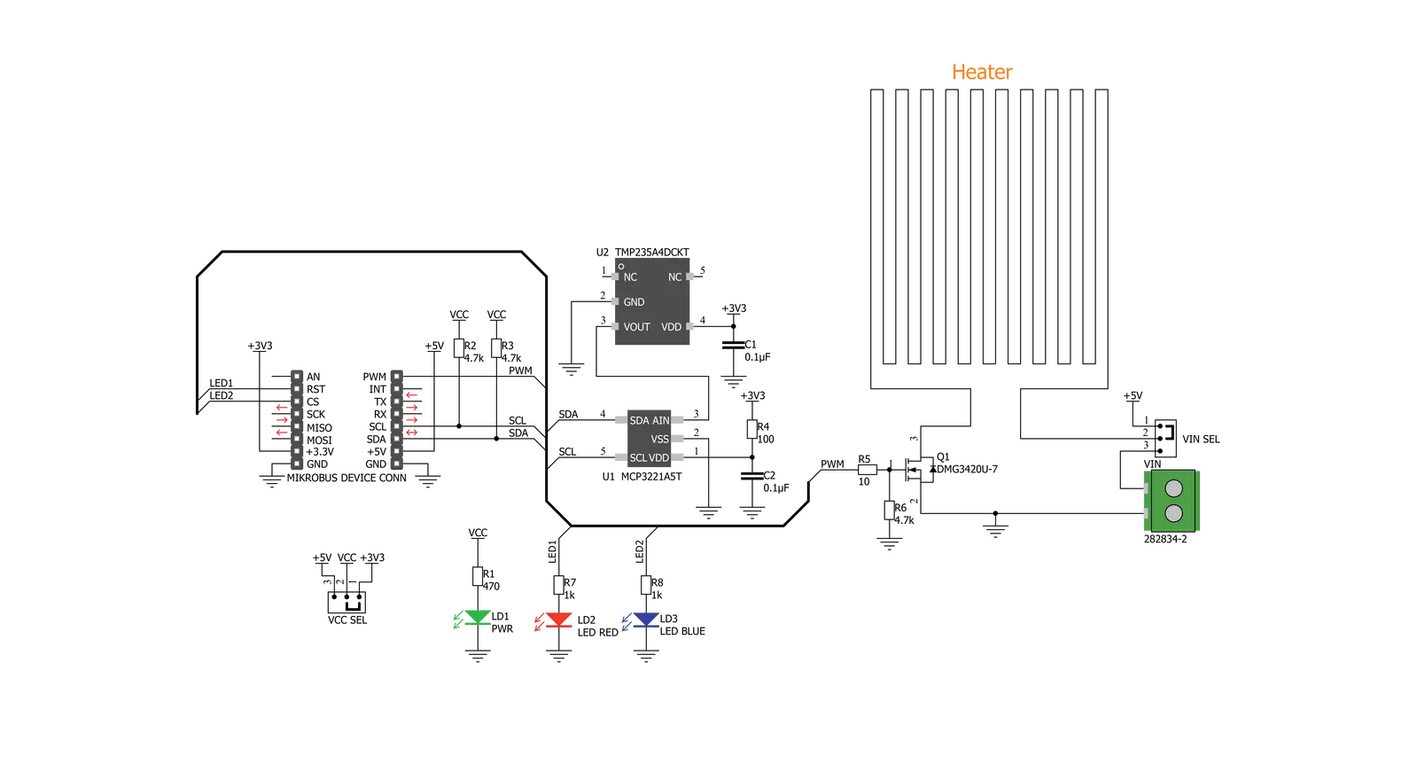
Heater Click is based on the TMP235, an onboard temperature sensor from Texas Instruments. It is designed with intention of PCB heater concept testing and useful tool for heating complete casing where staying in specified temperature range is crucial. Heater Click works on a principle of Joule heating, also known as resistance heating (resistive heating), a process by which the passage of an electric current thrrough a conductor produces heat. Energy dissipated per unit time is equall to current passing through resistor times electric potential difference. Heater Click allows PCB temperature adjusting and monitoring as it have embedded trace resistor on top layer of PCB. Resistor is made from copper 1oz thick and a pattern of 0.1mm wide track 1950mm long, this give us about 10 ohm resistance
at 25 degrees Celsius. With on bord VIN SEL jumper power supply can be selected as 5V from mikroBUS or any other voltage from external power supply at therminal block VIN. Using mikroBUS PWM pin power dissipation can be adjusted and therfore temperature controlled. Heater Click minimize temperature spread from embedded resistor by having PCB gaps between it and rest of the click bord and components, by doing so hot zone is easier to warm up and keeping it at exact temperature without affecting rest of the commponents. LEDs are connected to LD1 and LD2 GPIO pins and can be used for example to signal user if temperature is ramping up or achieved, or any other user defined signaling. Since the temperature rise in a heater is a function of its resistance and voltage, you don’t always
need to design a heater from scratch. So long as you can apply a specific voltage, you should be able to achieve your desired temperature and monitoring it through I2C. Temperature is monitored with TMP235 precision CMOS integrated-circuit linear analog temperature sensor with an output voltage proportional to temperature, The TMP235 device provides a positive slope output of 10 mV/°C over the full –40°C to +150°C temperature range. Using MCP3221 a 12-bit ADC, output voltage from temperature sensor can be red through I2C. Communication to the MCP3221 is performed using a 2-wire, I2C compatible interface. Standard (100 kHz) and Fast (400 kHz) I2C modes are available with the device.

Features overview
Development board
EasyAVR v8 is a development board designed to rapidly develop embedded applications based on 8-bit AVR microcontrollers (MCUs). Redesigned from the ground up, EasyAVR v8 offers a familiar set of standard features, as well as some new and unique features standard for the 8th generation of development boards: programming and debugging over the WiFi network, connectivity provided by USB-C connectors, support for a wide range of different MCUs, and more. The development board is designed so that the developer has everything that might be needed for the application development, following the Swiss Army knife concept: a highly advanced programmer/debugger module, a reliable power supply module, and a USB-UART connectivity option. EasyAVR v8 board offers several different DIP sockets, covering a wide range of 8-bit AVR MCUs, from the smallest
AVR MCU devices with only eight pins, all the way up to 40-pin "giants". The development board supports the well-established mikroBUS™ connectivity standard, offering five mikroBUS™ sockets, allowing access to a huge base of Click boards™. EasyAVR v8 offers two display options, allowing even the basic 8-bit AVR MCU devices to utilize them and display graphical or textual content. One of them is the 1x20 graphical display connector, compatible with the familiar Graphical Liquid Crystal Display (GLCD) based on the KS108 (or compatible) display driver, and EasyTFT board that contains TFT Color Display MI0283QT-9A, which is driven by ILI9341 display controller, capable of showing advanced graphical content. The other option is the 2x16 character LCD module, a four-bit display module with an embedded character-based display controller. It
requires minimal processing power from the host MCU for its operation. There is a wide range of useful interactive options at the disposal: high-quality buttons with selectable press levels, LEDs, pull-up/pulldown DIP switches, and more. All these features are packed on a single development board, which uses innovative manufacturing technologies, delivering a fluid and immersive working experience. The EasyAVR v8 development board is also integral to the MIKROE rapid development ecosystem. Natively supported by the MIKROE Software toolchain, backed up by hundreds of different Click board™ designs with their number growing daily, it covers many different prototyping and development aspects, thus saving precious development time.

Microcontroller Overview
MCU Card / MCU
Architecture
AVR
MCU Memory (KB)
32
Silicon Vendor
Microchip
Pin count
40
RAM (Bytes)
2048
Used MCU Pins
mikroBUS™ mapper
Take a closer look
Click board™ Schematic
Step by step
Project assembly

Start by selecting your development board and Click board™. Begin with the EasyAVR v8 as your development board.


Track your results in real time
Application Output
1. Application Output - In Debug mode, the 'Application Output' window enables real-time data monitoring, offering direct insight into execution results. Ensure proper data display by configuring the environment correctly using the provided tutorial.

2. UART Terminal - Use the UART Terminal to monitor data transmission via a USB to UART converter, allowing direct communication between the Click board™ and your development system. Configure the baud rate and other serial settings according to your project's requirements to ensure proper functionality. For step-by-step setup instructions, refer to the provided tutorial.

3. Plot Output - The Plot feature offers a powerful way to visualize real-time sensor data, enabling trend analysis, debugging, and comparison of multiple data points. To set it up correctly, follow the provided tutorial, which includes a step-by-step example of using the Plot feature to display Click board™ readings. To use the Plot feature in your code, use the function: plot(*insert_graph_name*, variable_name);. This is a general format, and it is up to the user to replace 'insert_graph_name' with the actual graph name and 'variable_name' with the parameter to be displayed.

Software Support
Library Description
This library contains API for Heater Click driver.
Key functions:
heater_read_data- This function writes data to the desired register.heater_read_mv- Read data in mVheater_read_temp- Read data in C
Open Source
Code example
The complete application code and a ready-to-use project are available through the NECTO Studio Package Manager for direct installation in the NECTO Studio. The application code can also be found on the MIKROE GitHub account.
/*!
 * \file
 * \brief heater Click example
 *
 * # Description
 *  The devices resolution depends on settings applied.
 *  User should consult the datasheet and choose resolution value
 *  that corresponds to the settings applied.
 *
 * ## Application Init
 *  Initialization of PWM module and start heating up
 *
 *  ## Application Task
 *  Durning the task device is heating up to 50 degree C and then
 *   cooling down to 40 degree C
 *
 * \author MikroE Team
 *
 */
// ------------------------------------------------------------------- INCLUDES

#include "board.h"
#include "log.h"
#include "heater.h"

// ------------------------------------------------------------------ VARIABLES

static heater_t heater;
static log_t logger;

static float temp_read;
static uint8_t status_dev;
static float duty_cycle_heating = 0.5;
static float duty_cycle_cooling = 0.0;
const float HOT_TEMP = 50.0;
const float COOL_TEMP = 40.0;

// ------------------------------------------------------ APPLICATION FUNCTIONS

void application_init ( void )
{
    log_cfg_t log_cfg;
    heater_cfg_t cfg;
    heater_config_t cfg1;

    /**
     * Logger initialization.
     * Default baud rate: 115200
     * Default log level: LOG_LEVEL_DEBUG
     * @note If USB_UART_RX and USB_UART_TX
     * are defined as HAL_PIN_NC, you will
     * need to define them manually for log to work.
     * See @b LOG_MAP_USB_UART macro definition for detailed explanation.
     */
    LOG_MAP_USB_UART( log_cfg );
    log_init( &logger, &log_cfg );
    log_info( &logger, "---- Application Init ----" );

    //  Click initialization.

    heater_cfg_setup( &cfg, &cfg1 );
    HEATER_MAP_MIKROBUS( cfg, MIKROBUS_1 );
    heater_init( &heater, &cfg, &cfg1 );


    heater_set_duty_cycle( &heater, duty_cycle_heating );
    heater_pwm_start( &heater );
    log_printf( &logger, " ***** APP INIT ***** \r\n" );
    Delay_ms ( 500 );
}

void application_task ( void )
{
    temp_read = heater_read_temp( &heater );

    if ( temp_read > HOT_TEMP )
    {
        heater_set_duty_cycle( &heater, duty_cycle_cooling );
        heater_set_led1_status( &heater, HEATER_LED_OFF );
        heater_set_led2_status( &heater, HEATER_LED_ON );
        log_printf( &logger,  " - Cooling off -\r\n" );
    }
    else if ( temp_read < COOL_TEMP )
    {
        heater_set_duty_cycle( &heater, duty_cycle_heating );
        heater_set_led1_status( &heater, HEATER_LED_ON );
        heater_set_led2_status( &heater, HEATER_LED_OFF );
        log_printf( &logger,  " - Heating up -\r\n" );
    }

    log_printf( &logger,  " - Temperature: %.2f degC\r\n", temp_read );

    log_printf( &logger, "***************\r\n" );

    Delay_ms ( 1000 );
}

int main ( void )
{
    /* Do not remove this line or clock might not be set correctly. */
    #ifdef PREINIT_SUPPORTED
    preinit();
    #endif

    application_init( );

    for ( ; ; )
    {
        application_task( );
    }

    return 0;
}


// ------------------------------------------------------------------------ END
Additional Support
Resources
Category:Temperature & humidity


