Achieve infrared remote control with TSOP38238 and ATmega1284
Take command with ease!

Published Jul 09, 2024
Click board™
IR Click
Dev. board
EasyAVR v8
Compiler
NECTO Studio
MCU
ATmega1284
Enhance your project's capabilities by integrating IR remote control functionality that improves your system and allows you more flexibility
A
A
Hardware Overview
How does it work?
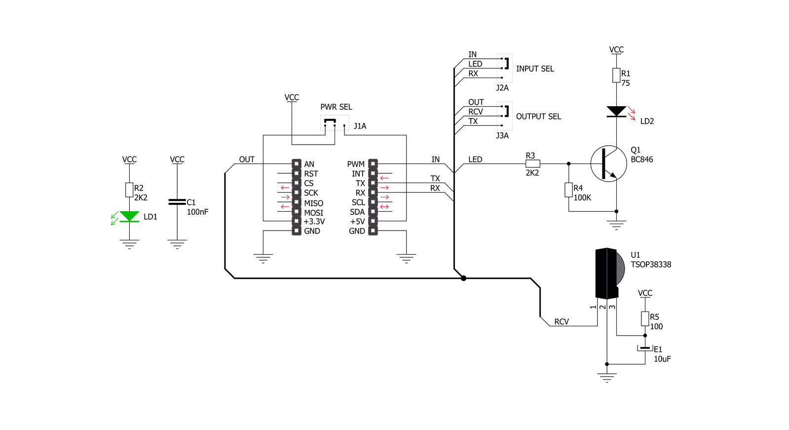
IR Click is based on the TSOP38238, a miniaturized sensor for receiving the modulated signal of QEE113 IR emitting diode from Vishay Semiconductors. All Vishay IR receivers have the same circuit architecture consisting of a photodetector, pre-amplifier, and automatic gain control (ACG) to surpass ambient noise with transmitted signals. Tuned to a carrier frequency of 38kHz with a transmission distance of 45m and beam and viewing angle of 45 degrees, this Click board™ represents a compact and easy solution allowing you to control A/V equipment with an IR remote controller. The infrared signal generates an equivalent photocurrent in the integrated photo PIN diode. The DC part of the signal is blocked in the
bias circuit, while the AC part is passed to a trans-impedance amplifier, followed by an automatic gain-control amplifier and an integrated bandpass filter. A comparator, an integrator, and a Schmitt Trigger stage perform the final signal conditioning. The blocks “Automatic Gain Control” and “Automatic Threshold Control” dynamically control the operating points and the threshold levels required to suppress noise from disturbance sources. The digital output signal has an active-low polarity and consists of an incoming optical burst envelope signal without the carrier frequency. IR Click communicates with the target MCU via selectable GPIO lines. The selection can be made by positioning SMD jumpers to an appropriate
position marked as GPIO or UART. The default configuration of this Click board™ allows transmission via the PWM pin of the mikroBUS™ socket and reception via the AN pin, while the other configuration allows communication using TX and RX pins. This Click board™ can operate with either 3.3V or 5V logic voltage levels selected via the PWR SEL jumper. This way, both 3.3V and 5V capable MCUs can use the communication lines properly. Also, this Click board™ comes equipped with a library containing easy-to-use functions and an example code that can be used as a reference for further development.

Features overview
Development board
EasyAVR v8 is a development board designed to rapidly develop embedded applications based on 8-bit AVR microcontrollers (MCUs). Redesigned from the ground up, EasyAVR v8 offers a familiar set of standard features, as well as some new and unique features standard for the 8th generation of development boards: programming and debugging over the WiFi network, connectivity provided by USB-C connectors, support for a wide range of different MCUs, and more. The development board is designed so that the developer has everything that might be needed for the application development, following the Swiss Army knife concept: a highly advanced programmer/debugger module, a reliable power supply module, and a USB-UART connectivity option. EasyAVR v8 board offers several different DIP sockets, covering a wide range of 8-bit AVR MCUs, from the smallest
AVR MCU devices with only eight pins, all the way up to 40-pin "giants". The development board supports the well-established mikroBUS™ connectivity standard, offering five mikroBUS™ sockets, allowing access to a huge base of Click boards™. EasyAVR v8 offers two display options, allowing even the basic 8-bit AVR MCU devices to utilize them and display graphical or textual content. One of them is the 1x20 graphical display connector, compatible with the familiar Graphical Liquid Crystal Display (GLCD) based on the KS108 (or compatible) display driver, and EasyTFT board that contains TFT Color Display MI0283QT-9A, which is driven by ILI9341 display controller, capable of showing advanced graphical content. The other option is the 2x16 character LCD module, a four-bit display module with an embedded character-based display controller. It
requires minimal processing power from the host MCU for its operation. There is a wide range of useful interactive options at the disposal: high-quality buttons with selectable press levels, LEDs, pull-up/pulldown DIP switches, and more. All these features are packed on a single development board, which uses innovative manufacturing technologies, delivering a fluid and immersive working experience. The EasyAVR v8 development board is also integral to the MIKROE rapid development ecosystem. Natively supported by the MIKROE Software toolchain, backed up by hundreds of different Click board™ designs with their number growing daily, it covers many different prototyping and development aspects, thus saving precious development time.

Microcontroller Overview
MCU Card / MCU

Architecture
AVR
MCU Memory (KB)
128
Silicon Vendor
Microchip
Pin count
40
RAM (Bytes)
16384
Used MCU Pins
mikroBUS™ mapper
Take a closer look
Click board™ Schematic
Step by step
Project assembly

Start by selecting your development board and Click board™. Begin with the EasyAVR v8 as your development board.


Track your results in real time
Application Output
1. Application Output - In Debug mode, the 'Application Output' window enables real-time data monitoring, offering direct insight into execution results. Ensure proper data display by configuring the environment correctly using the provided tutorial.

2. UART Terminal - Use the UART Terminal to monitor data transmission via a USB to UART converter, allowing direct communication between the Click board™ and your development system. Configure the baud rate and other serial settings according to your project's requirements to ensure proper functionality. For step-by-step setup instructions, refer to the provided tutorial.

3. Plot Output - The Plot feature offers a powerful way to visualize real-time sensor data, enabling trend analysis, debugging, and comparison of multiple data points. To set it up correctly, follow the provided tutorial, which includes a step-by-step example of using the Plot feature to display Click board™ readings. To use the Plot feature in your code, use the function: plot(*insert_graph_name*, variable_name);. This is a general format, and it is up to the user to replace 'insert_graph_name' with the actual graph name and 'variable_name' with the parameter to be displayed.

Software Support
Library Description
This library contains API for IR Click driver.
Key functions:
ir_get_an_state- IR get AN pin state function.ir_nec_send_command- IR NEC send data function.ir_nec_read_command- IR NEC data reading function.
Open Source
Code example
The complete application code and a ready-to-use project are available through the NECTO Studio Package Manager for direct installation in the NECTO Studio. The application code can also be found on the MIKROE GitHub account.
/*!
 * @file main.c
 * @brief IR Click Example.
 *
 * # Description
 * This is an example that demonstrates the use of the IR Click board.
 *
 * The demo application is composed of two sections :
 *
 * ## Application Init
 * Initialization driver enables - GPIO and Log.
 *
 * ## Application Task
 * This example contains two parts :
 * - Transmitter mode - Sends data using NEC protocol.
 * - Receiver mode - Reads data that is been sent using NEC protocol and
 *                   displaying it on the UART terminal.
 *
 * @author Stefan Ilic
 *
 */

#include "board.h"
#include "log.h"
#include "ir.h"

static ir_t ir;
static log_t logger;

uint8_t tx_data[ 8 ] = { 'M', 'i', 'k', 'r', 'o', 'E', '\r', '\n' };

#define IR_TRANSMITTER_MODE

void application_init ( void )
{
    log_cfg_t log_cfg;  /**< Logger config object. */
    ir_cfg_t ir_cfg;    /**< Click config object. */

    /**
     * Logger initialization.
     * Default baud rate: 115200
     * Default log level: LOG_LEVEL_DEBUG
     * @note If USB_UART_RX and USB_UART_TX
     * are defined as HAL_PIN_NC, you will
     * need to define them manually for log to work.
     * See @b LOG_MAP_USB_UART macro definition for detailed explanation.
     */
    LOG_MAP_USB_UART( log_cfg );
    log_init( &logger, &log_cfg );
    log_info( &logger, " Application Init " );

    // Click initialization.
    ir_cfg_setup( &ir_cfg );
    IR_MAP_MIKROBUS( ir_cfg, MIKROBUS_1 );
    err_t error_flag = ir_init( &ir, &ir_cfg );
    if ( ( UART_ERROR == error_flag ) || ( PWM_ERROR == error_flag ) )
    {
        log_error( &logger, " Communication init." );
        for ( ; ; );
    }

    log_info( &logger, " Application Task " );
    log_printf( &logger, "- - - - - - - - - - - - \r\n" );

    #ifdef IR_TRANSMITTER_MODE
        log_printf( &logger, "-  Transmitter mode   - \r\n" );
    #else
        log_printf( &logger, "-    Receiver mode    - \r\n" );
    #endif
    log_printf( &logger, "- - - - - - - - - - - - \r\n" );
}

void application_task ( void )
{
    #ifdef IR_TRANSMITTER_MODE
        log_printf( &logger, " Sending message." );

        for ( uint8_t cnt = 0; cnt < 8; cnt++ )
        {
            ir_nec_send_command( &ir, 0x00, tx_data[ cnt ] );
            log_printf( &logger, "." );
            Delay_ms ( 50 );
        }

        log_printf( &logger, "\r\n Message sent! \r\n" );
        log_printf( &logger, "- - - - - - - - - - - - \r\n" );
        Delay_ms ( 500 );
    #else
        uint8_t arr;
        char rx_data;

        err_t err_flag = ir_nec_read_command ( &ir, &arr, &rx_data );

        if ( IR_OK == err_flag )
        {
            log_printf( &logger, "%c", rx_data );
        }
        else
        {
            log_printf( &logger, "Read ERROR! \r\n" );
        }
        Delay_ms ( 50 );
    #endif
}

int main ( void )
{
    /* Do not remove this line or clock might not be set correctly. */
    #ifdef PREINIT_SUPPORTED
    preinit();
    #endif

    application_init( );

    for ( ; ; )
    {
        application_task( );
    }

    return 0;
}

// ------------------------------------------------------------------------ END


