Experience the future of climate control with SHT31-DIS and ATmega644P
Climate control, simplified.
Published Jul 09, 2024
Click board™
SHT Click
Dev. board
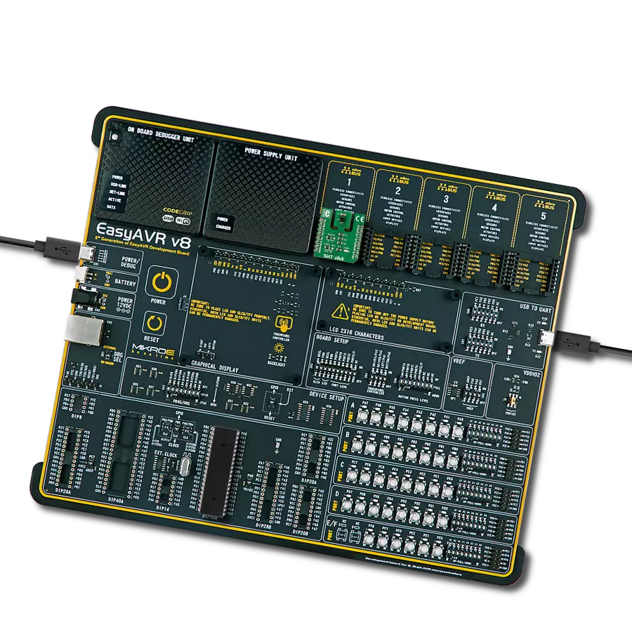
EasyAVR v8
Compiler
NECTO Studio
MCU
ATmega644P
Our temperature and humidity sensing solution combines cutting-edge precision with unparalleled comfort, ensuring the perfect environment for your well-being
A
A
Hardware Overview
How does it work?
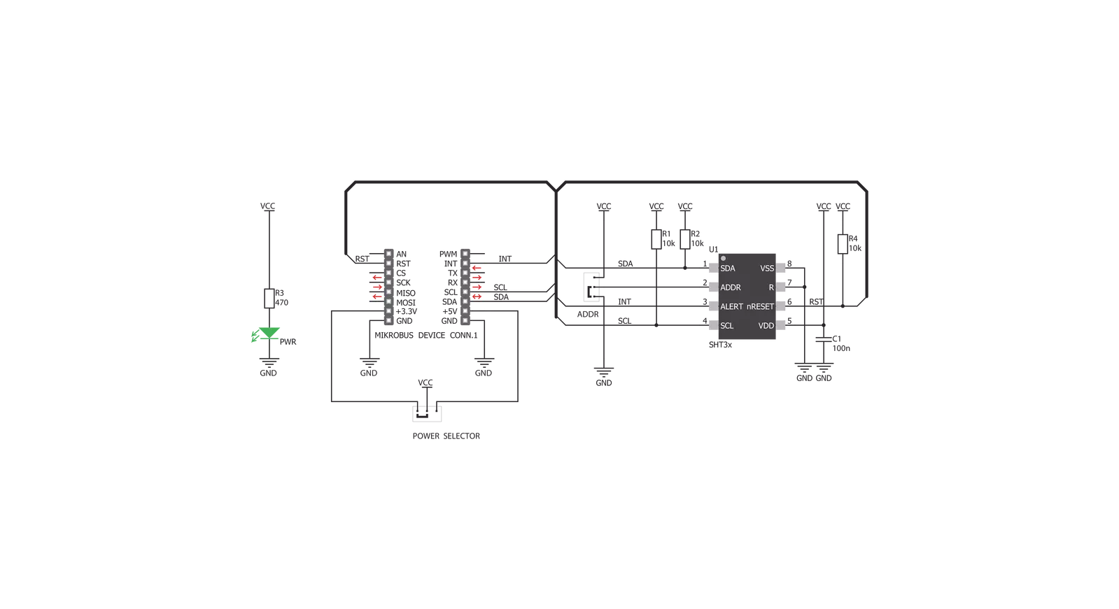
SHT Click is based on the SHT31-DIS, a humidity and temperature sensor from Sensirion. The SHT31-DIS is a robust and reliable sensor, and even when exposed to conditions outside its normal range, it can recalibrate itself once conditions stabilize. The sensor performs best when operated within the recommended normal temperature and humidity range of 5°C up to 60°C and 20%RH up to 80%RH, respectively. Long-term exposure to conditions outside the normal range, especially at high humidity, may temporarily offset the RH signal. After returning to the normal temperature
and humidity range, the sensor will slowly return to a calibration state by itself. Also, note that prolonged exposure to extreme conditions may accelerate aging. The SHT Click communicates with the host MCU using an I2C interface over the mikroBUS™ socket, with communication speeds of up to 1MHz. This Click board™ allows the selection of one of two available I2C addresses via the ADDR jumper, where I2C address 0 is selected by default. To reset the SHT31-DIS sensor, there is an RST pin with an active LOW state. The SHT31-DIS also features alert functions and can send
interrupt signals over the INT pin of the mikroBUS™ socket. The output of this pin depends on the RH/T reading relative to programmable limits. This Click board™ can operate with either 3.3V or 5V logic voltage levels selected via the PWR SEL jumper. This way, both 3.3V and 5V capable MCUs can use the communication lines properly. Also, this Click board™ comes equipped with a library containing easy-to-use functions and an example code that can be used as a reference for further development.

Features overview
Development board
EasyAVR v8 is a development board designed to rapidly develop embedded applications based on 8-bit AVR microcontrollers (MCUs). Redesigned from the ground up, EasyAVR v8 offers a familiar set of standard features, as well as some new and unique features standard for the 8th generation of development boards: programming and debugging over the WiFi network, connectivity provided by USB-C connectors, support for a wide range of different MCUs, and more. The development board is designed so that the developer has everything that might be needed for the application development, following the Swiss Army knife concept: a highly advanced programmer/debugger module, a reliable power supply module, and a USB-UART connectivity option. EasyAVR v8 board offers several different DIP sockets, covering a wide range of 8-bit AVR MCUs, from the smallest
AVR MCU devices with only eight pins, all the way up to 40-pin "giants". The development board supports the well-established mikroBUS™ connectivity standard, offering five mikroBUS™ sockets, allowing access to a huge base of Click boards™. EasyAVR v8 offers two display options, allowing even the basic 8-bit AVR MCU devices to utilize them and display graphical or textual content. One of them is the 1x20 graphical display connector, compatible with the familiar Graphical Liquid Crystal Display (GLCD) based on the KS108 (or compatible) display driver, and EasyTFT board that contains TFT Color Display MI0283QT-9A, which is driven by ILI9341 display controller, capable of showing advanced graphical content. The other option is the 2x16 character LCD module, a four-bit display module with an embedded character-based display controller. It
requires minimal processing power from the host MCU for its operation. There is a wide range of useful interactive options at the disposal: high-quality buttons with selectable press levels, LEDs, pull-up/pulldown DIP switches, and more. All these features are packed on a single development board, which uses innovative manufacturing technologies, delivering a fluid and immersive working experience. The EasyAVR v8 development board is also integral to the MIKROE rapid development ecosystem. Natively supported by the MIKROE Software toolchain, backed up by hundreds of different Click board™ designs with their number growing daily, it covers many different prototyping and development aspects, thus saving precious development time.

Microcontroller Overview
MCU Card / MCU

Architecture
AVR
MCU Memory (KB)
64
Silicon Vendor
Microchip
Pin count
40
RAM (Bytes)
4096
Used MCU Pins
mikroBUS™ mapper
Take a closer look
Click board™ Schematic
Step by step
Project assembly

Start by selecting your development board and Click board™. Begin with the EasyAVR v8 as your development board.


Track your results in real time
Application Output
1. Application Output - In Debug mode, the 'Application Output' window enables real-time data monitoring, offering direct insight into execution results. Ensure proper data display by configuring the environment correctly using the provided tutorial.

2. UART Terminal - Use the UART Terminal to monitor data transmission via a USB to UART converter, allowing direct communication between the Click board™ and your development system. Configure the baud rate and other serial settings according to your project's requirements to ensure proper functionality. For step-by-step setup instructions, refer to the provided tutorial.

3. Plot Output - The Plot feature offers a powerful way to visualize real-time sensor data, enabling trend analysis, debugging, and comparison of multiple data points. To set it up correctly, follow the provided tutorial, which includes a step-by-step example of using the Plot feature to display Click board™ readings. To use the Plot feature in your code, use the function: plot(*insert_graph_name*, variable_name);. This is a general format, and it is up to the user to replace 'insert_graph_name' with the actual graph name and 'variable_name' with the parameter to be displayed.

Software Support
Library Description
This library contains API for SHT Click driver.
Key functions:
sht_temp_ss- Returns temperature measurement in single shot mode.sht_hum_ss- Returns humidity measurement in single shot mode.sht_heater_control- Sets the heater state.
Open Source
Code example
The complete application code and a ready-to-use project are available through the NECTO Studio Package Manager for direct installation in the NECTO Studio. The application code can also be found on the MIKROE GitHub account.
/*!
 * \file
 * \brief Sht Click example
 *
 * # Description
 * This application enables usage of the temperature and humidity sensor.
 *
 * The demo application is composed of two sections :
 *
 * ## Application Init
 * Initialize the communication interface and configure the Click board.
 *
 * ## Application Task
 * Temperature and humidity data is measured and read from the sensor.
 * After the data has been read it is displayed on the serial port.
 *
 * \author MikroE Team
 *
 */
// ------------------------------------------------------------------- INCLUDES

#include "board.h"
#include "log.h"
#include "sht.h"

// ------------------------------------------------------------------ VARIABLES

static sht_t sht;
static log_t logger;

// ------------------------------------------------------ APPLICATION FUNCTIONS

void application_init ( void )
{
    log_cfg_t log_cfg;
    sht_cfg_t cfg;

    /**
     * Logger initialization.
     * Default baud rate: 115200
     * Default log level: LOG_LEVEL_DEBUG
     * @note If USB_UART_RX and USB_UART_TX
     * are defined as HAL_PIN_NC, you will
     * need to define them manually for log to work.
     * See @b LOG_MAP_USB_UART macro definition for detailed explanation.
     */
    LOG_MAP_USB_UART( log_cfg );
    log_init( &logger, &log_cfg );
    log_info( &logger, " Application Init " );

    //  Click initialization.
    sht_cfg_setup( &cfg );
    SHT_MAP_MIKROBUS( cfg, MIKROBUS_1 );
    sht_init( &sht, &cfg );

    sht_reset( &sht );
    sht_hw_reset( &sht );
    Delay_ms ( 1000 );
    Delay_ms ( 1000 );

    log_info( &logger, " Application Task " );
}

void application_task ( void )
{
    float temperature = 0;
    float humidity = 0;

    temperature = sht_temp_ss( &sht );
    log_printf( &logger, " Temperature: %.2f degC\r\n", temperature );

    humidity = sht_hum_ss( &sht );
    log_printf( &logger, " Humidity: %.2f %%\r\n\n", humidity );

    Delay_ms ( 1000 );
}

int main ( void )
{
    /* Do not remove this line or clock might not be set correctly. */
    #ifdef PREINIT_SUPPORTED
    preinit();
    #endif

    application_init( );

    for ( ; ; )
    {
        application_task( );
    }

    return 0;
}


// ------------------------------------------------------------------------ END
Additional Support
Resources
Category:Temperature & humidity


