Revolutionize data acquisition and remote monitoring applications with MAX399 and ATmega644PA
One UART, four RS-232 friends: CMOS MUX marvel!

Published Jul 11, 2024
Click board™
UART MUX 2 Click
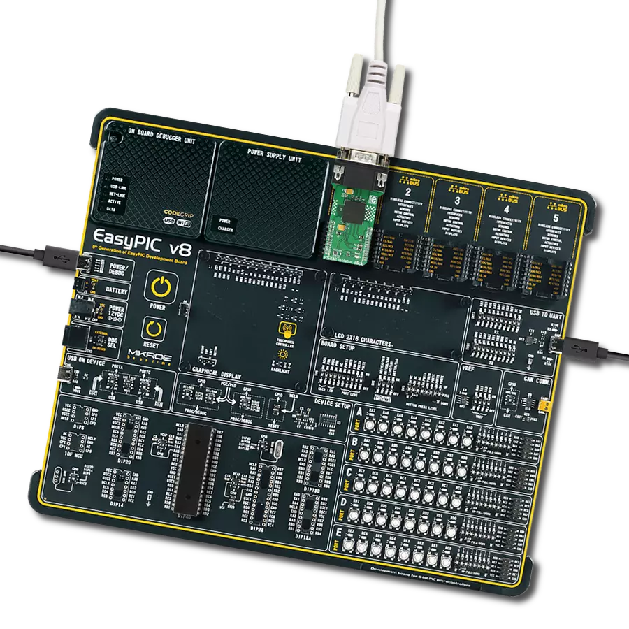
Dev. board
EasyAVR v8
Compiler
NECTO Studio
MCU
ATmega644PA
Optimize your UART interface and simplify serial data communication by implementing our CMOS analog multiplexer, allowing four remote RS-232 transceivers to efficiently share a single UART connection
A
A
Hardware Overview
How does it work?
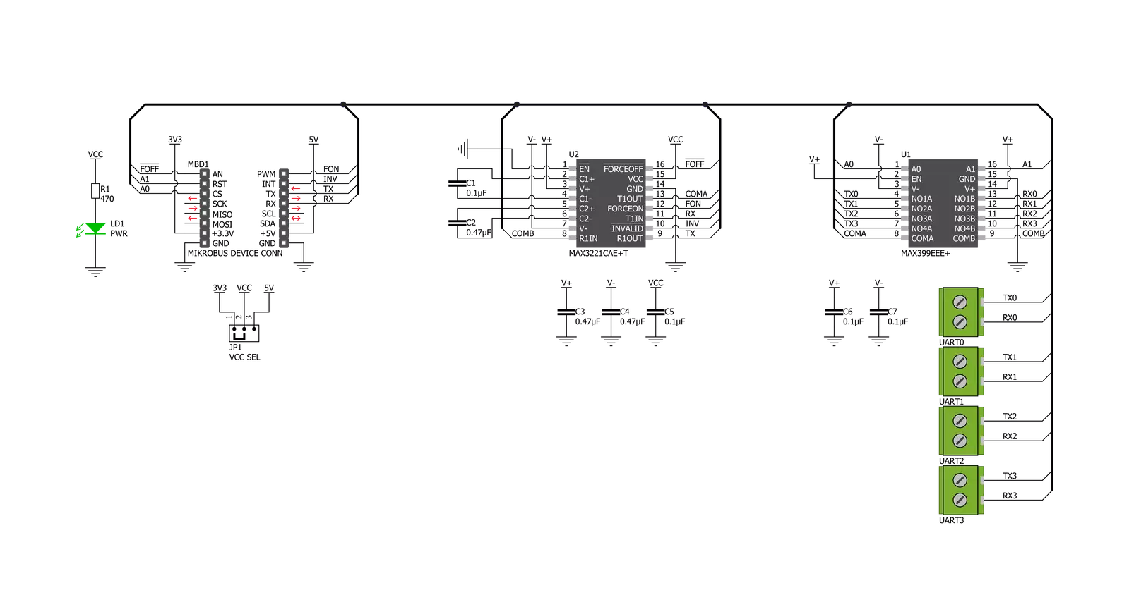
UART MUX 2 Click is based on the MAX399, a precise CMOS analog multiplexer that enables pseudo-multidrop RS232 transmission from Analog Devices. This multiplexer allows multiple channels, in this case, four, to share a single UART interface. It offers fast switching speeds with a transition time of less than 250ns and low on-resistance of less than 100Ω while retaining CMOS-logic input compatibility and fast switching. The dual four-to-one multiplexer permits transceiver MAX3221 to form a network with the four remote transceivers connected to terminals labeled as UART0-UART3 in the upper part of the Click board™. The circuit's supply-voltage range (3V to 5.5V) makes it compatible with 3V and 5V logic. MAX399 receives its power directly from the power terminals of MAX3221, whose ±5.5V outputs come
from an internal charge pump. The multiplexer handles rail-to-rail signals, so obtaining its power from MAX3221 ensures that RS232 signals pass directly through, regardless of amplitude. The UART MUX Click communicates with MCU through MAX3221 using the UART interface for the data transfer. The MAX3221 can run at data rates up to 250 kbps while maintaining RS232-compliant output levels. Channel selection is performed through a set of specific GPIO pins, labeled as A0 and A1, routed on the CS and RST pins of the mikroBUS™ socket. Selecting channel 1, for instance, enables MAX3221 to communicate with UART0 without being loaded by UART1 to UART3. Pulldown resistors inside the remote transceivers force the outputs of un-selected receivers to a known state. In addition to a
channel selection, this Click board™ also has an automatic power-down feature that can be turned off when ON and OFF pins are high, routed on the PWM and AN pins of the mikroBUS™ socket. Also, it uses the interrupt pin of the mikroBUS™ labeled as INV as an invalid indicator, making interfacing with the RS232 simple and easy, indicating whether a valid RS232 signal is present. This Click board™ can operate with either 3.3V or 5V logic voltage levels selected via the VCC SEL jumper. This way, both 3.3V and 5V capable MCUs can use the communication lines properly. Also, this Click board™ comes equipped with a library containing easy-to-use functions and an example code that can be used as a reference for further development.


Features overview
Development board
EasyAVR v8 is a development board designed to rapidly develop embedded applications based on 8-bit AVR microcontrollers (MCUs). Redesigned from the ground up, EasyAVR v8 offers a familiar set of standard features, as well as some new and unique features standard for the 8th generation of development boards: programming and debugging over the WiFi network, connectivity provided by USB-C connectors, support for a wide range of different MCUs, and more. The development board is designed so that the developer has everything that might be needed for the application development, following the Swiss Army knife concept: a highly advanced programmer/debugger module, a reliable power supply module, and a USB-UART connectivity option. EasyAVR v8 board offers several different DIP sockets, covering a wide range of 8-bit AVR MCUs, from the smallest
AVR MCU devices with only eight pins, all the way up to 40-pin "giants". The development board supports the well-established mikroBUS™ connectivity standard, offering five mikroBUS™ sockets, allowing access to a huge base of Click boards™. EasyAVR v8 offers two display options, allowing even the basic 8-bit AVR MCU devices to utilize them and display graphical or textual content. One of them is the 1x20 graphical display connector, compatible with the familiar Graphical Liquid Crystal Display (GLCD) based on the KS108 (or compatible) display driver, and EasyTFT board that contains TFT Color Display MI0283QT-9A, which is driven by ILI9341 display controller, capable of showing advanced graphical content. The other option is the 2x16 character LCD module, a four-bit display module with an embedded character-based display controller. It
requires minimal processing power from the host MCU for its operation. There is a wide range of useful interactive options at the disposal: high-quality buttons with selectable press levels, LEDs, pull-up/pulldown DIP switches, and more. All these features are packed on a single development board, which uses innovative manufacturing technologies, delivering a fluid and immersive working experience. The EasyAVR v8 development board is also integral to the MIKROE rapid development ecosystem. Natively supported by the MIKROE Software toolchain, backed up by hundreds of different Click board™ designs with their number growing daily, it covers many different prototyping and development aspects, thus saving precious development time.

Microcontroller Overview
MCU Card / MCU
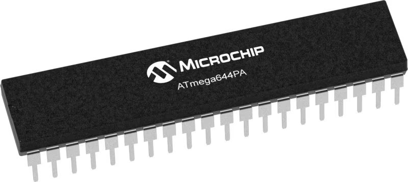
Architecture
AVR
MCU Memory (KB)
64
Silicon Vendor
Microchip
Pin count
40
RAM (Bytes)
4096
Used MCU Pins
mikroBUS™ mapper
Take a closer look
Click board™ Schematic
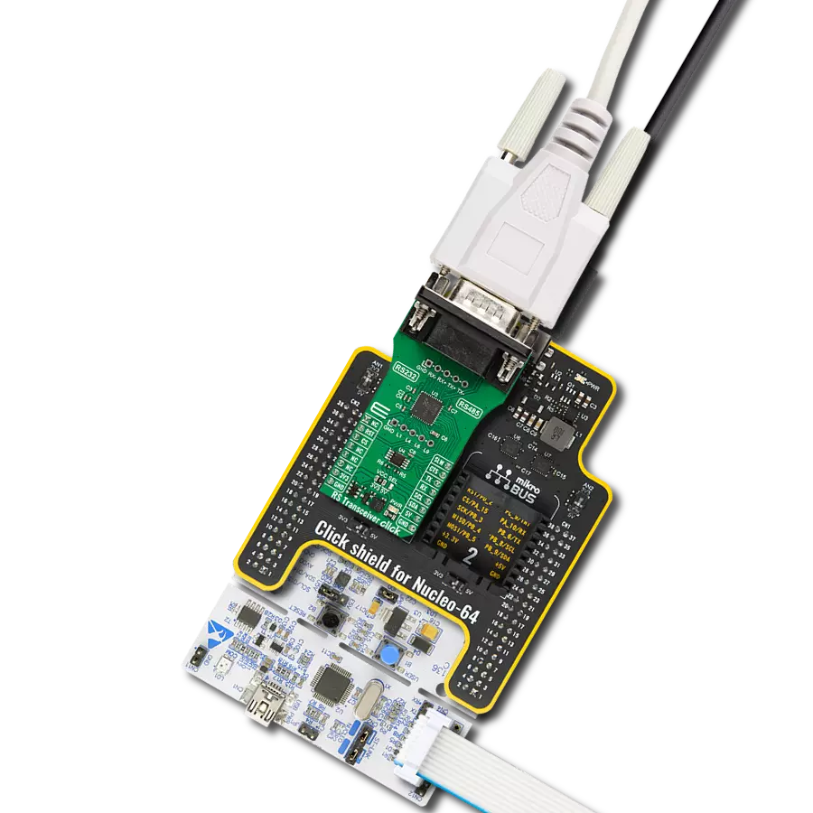
Step by step
Project assembly

Start by selecting your development board and Click board™. Begin with the EasyAVR v8 as your development board.


Track your results in real time
Application Output
1. Application Output - In Debug mode, the 'Application Output' window enables real-time data monitoring, offering direct insight into execution results. Ensure proper data display by configuring the environment correctly using the provided tutorial.

2. UART Terminal - Use the UART Terminal to monitor data transmission via a USB to UART converter, allowing direct communication between the Click board™ and your development system. Configure the baud rate and other serial settings according to your project's requirements to ensure proper functionality. For step-by-step setup instructions, refer to the provided tutorial.

3. Plot Output - The Plot feature offers a powerful way to visualize real-time sensor data, enabling trend analysis, debugging, and comparison of multiple data points. To set it up correctly, follow the provided tutorial, which includes a step-by-step example of using the Plot feature to display Click board™ readings. To use the Plot feature in your code, use the function: plot(*insert_graph_name*, variable_name);. This is a general format, and it is up to the user to replace 'insert_graph_name' with the actual graph name and 'variable_name' with the parameter to be displayed.

Software Support
Library Description
This library contains API for UART MUX 2 Click driver.
Key functions:
uartmux2_set_operation_mode- UART MUX 2 set operation mode functionuartmux2_set_channel- UART MUX 2 set channel functionuartmux2_send_data- UART MUX 2 data writing function
Open Source
Code example
The complete application code and a ready-to-use project are available through the NECTO Studio Package Manager for direct installation in the NECTO Studio. The application code can also be found on the MIKROE GitHub account.
/*!
 * @file main.c
 * @brief UART MUX 2 Click Example.
 *
 * # Description
 * This library contains API for UART MUX 2 Click driver.
 * This example transmits/receives and processes data from UART MUX 2 Clicks.
 * The library initializes and defines the UART bus drivers
 * to transmit or receive data.
 *
 * The demo application is composed of two sections :
 *
 * ## Application Init
 * Initializes driver and set UART channel module.
 *
 * ## Application Task
 * Transmitter/Receiver task depend on uncommented code.
 * Receiver logging each received byte to the UART for data logging,
 * while transmitted send messages every 2 seconds.
 *
 * ## Additional Function
 * - static void uartmux2_clear_app_buf ( void ) - Function clears memory of app_buf.
 * - static err_t uartmux2_process ( void ) - The general process of collecting presponce
 * that a module sends.
 *
 * @author Nenad Filipovic
 *
 */

#include "board.h"
#include "log.h"
#include "uartmux2.h"

#define PROCESS_BUFFER_SIZE 200

#define TRANSMITTER
// #define RECIEVER

static uartmux2_t uartmux2;
static log_t logger;
static uint8_t uart_ch;
static char app_buf[ PROCESS_BUFFER_SIZE ] = { 0 };
static int32_t app_buf_len = 0;
static int32_t app_buf_cnt = 0;

unsigned char demo_message[ 9 ] = { 'M', 'i', 'k', 'r', 'o', 'E', 13, 10, 0 };

/**
 * @brief UART MUX 2 clearing application buffer.
 * @details This function clears memory of application buffer and reset it's length and counter.
 * @note None.
 */
static void uartmux2_clear_app_buf ( void );

/**
 * @brief UART MUX 2 data reading function.
 * @details This function reads data from device and concats data to application buffer.
 *
 * @return @li @c  0 - Read some data.
 *         @li @c -1 - Nothing is read.
 *         @li @c -2 - Application buffer overflow.
 *
 * See #err_t definition for detailed explanation.
 * @note None.
 */
static err_t uartmux2_process ( void );

void application_init ( void ) {
    log_cfg_t log_cfg;  /**< Logger config object. */
    uartmux2_cfg_t uartmux2_cfg;  /**< Click config object. */

    /**
     * Logger initialization.
     * Default baud rate: 115200
     * Default log level: LOG_LEVEL_DEBUG
     * @note If USB_UART_RX and USB_UART_TX
     * are defined as HAL_PIN_NC, you will
     * need to define them manually for log to work.
     * See @b LOG_MAP_USB_UART macro definition for detailed explanation.
     */
    LOG_MAP_USB_UART( log_cfg );
    log_init( &logger, &log_cfg );
    log_printf( &logger, "\r\n Application Init \r\n" );

    // Click initialization.

    uartmux2_cfg_setup( &uartmux2_cfg );
    UARTMUX2_MAP_MIKROBUS( uartmux2_cfg, MIKROBUS_1 );
    err_t init_flag  = uartmux2_init( &uartmux2, &uartmux2_cfg );
    if ( init_flag == UART_ERROR ) {
        log_error( &logger, " Application Init Error. " );
        log_info( &logger, " Please, run program again... " );

        for ( ; ; );
    }

    uartmux2_default_cfg ( &uartmux2 );
    app_buf_len = 0;
    app_buf_cnt = 0;
    log_printf( &logger, "\r\n Application Task \r\n" );
    log_printf( &logger, "------------------\r\n" );
    Delay_ms ( 500 );

    #ifdef TRANSMITTER

        log_printf( &logger, "    Send data:    \r\n" );
        log_printf( &logger, "      mikroE      \r\n" );
        log_printf( &logger, "------------------\r\n" );
        log_printf( &logger, "  Transmit data   \r\n" );
        Delay_ms ( 1000 );

    #endif

    #ifdef RECIEVER

        uart_ch = UARTMUX2_CHANNEL_0;
        log_printf( &logger, "   Receive data  \r\n" );
        log_printf( &logger, "      UART%u \r\n", ( uint16_t ) uart_ch );
        uartmux2_set_channel( &uartmux2, uart_ch );
        Delay_ms ( 1000 );
        Delay_ms ( 1000 );

    #endif

    log_printf( &logger, "------------------\r\n" );
}

void application_task ( void ) {
    #ifdef TRANSMITTER

    for ( uart_ch = UARTMUX2_CHANNEL_0; uart_ch <= UARTMUX2_CHANNEL_3; uart_ch++ ) {
        uartmux2_set_channel( &uartmux2, uart_ch );
        Delay_ms ( 100 );
        uartmux2_send_data( &uartmux2, demo_message );
        log_printf( &logger, "  UART%u : ", ( uint16_t ) uart_ch );

        for ( uint8_t cnt = 0; cnt < 9; cnt ++ ) {
            log_printf( &logger, "%c", demo_message[ cnt ] );
            Delay_ms ( 100 );
        }
    }

    log_printf( &logger, "------------------\r\n" );
    Delay_ms ( 100 );


    #endif

    #ifdef RECIEVER

    uartmux2_process( );

    if ( app_buf_len > 0 ) {
        log_printf( &logger, "%s", app_buf );
        uartmux2_clear_app_buf(  );
    }

    #endif
}

int main ( void )
{
    /* Do not remove this line or clock might not be set correctly. */
    #ifdef PREINIT_SUPPORTED
    preinit();
    #endif

    application_init( );

    for ( ; ; )
    {
        application_task( );
    }

    return 0;
}

static void uartmux2_clear_app_buf ( void ) {
    memset( app_buf, 0, app_buf_len );
    app_buf_len = 0;
    app_buf_cnt = 0;
}

static err_t uartmux2_process ( void ) {
    int32_t rx_size;
    char rx_buff[ PROCESS_BUFFER_SIZE ] = { 0 };

    rx_size = uartmux2_generic_read( &uartmux2, rx_buff, PROCESS_BUFFER_SIZE );

    if ( rx_size > 0 ) {
        int32_t buf_cnt = 0;

        if ( app_buf_len + rx_size >= PROCESS_BUFFER_SIZE ) {
            uartmux2_clear_app_buf(  );
            return -2;
        } else {
            buf_cnt = app_buf_len;
            app_buf_len += rx_size;
        }

        for ( int32_t rx_cnt = 0; rx_cnt < rx_size; rx_cnt++ ) {
            if ( rx_buff[ rx_cnt ] != 0 ) {
                app_buf[ ( buf_cnt + rx_cnt ) ] = rx_buff[ rx_cnt ];
            } else {
                app_buf_len--;
            }

        }
        return 0;
    }
    return -1;
}

// ------------------------------------------------------------------------ END