Achieve a deeper understanding of UVB radiation with GUVB-C31SM and ATmega1284
Safeguarding your skin: The game-changing UVB sensing solution
Published Jul 09, 2024
Click board™
UVB Click
Dev. board
EasyAVR v8
Compiler
NECTO Studio
MCU
ATmega1284
Discover how our solution delivers accurate UVB data for informed decisions and healthier living
A
A
Hardware Overview
How does it work?
UVB Click is based on GUVB-C31SM, a digital UV sensor from GenUV. The sensor detects UVB light, as it includes on-chip GaN Sensors for UVB. The current generated by photo detectors is converted and measured by ADC and changed to 16-bit resolution digital data. The measured data can be delivered to host via I2C serial interface. Spectral responsivity of sensor is from 240nm up to 320nm which covers full range of UVB spectrum that's defined as light with wavelength from 280nm up to 315nm. The atmosphere blocks about 77% of the Sun's UV, of the ultraviolet radiation that reaches the Earth's surface, more than 95% is the longer
wavelengths of UVA, with the small remainder UVB. Overexposure to UVB radiation not only can cause sunburn but also some forms of skin cancer. UVB radiation can cause direct DNA damage. This cancer connection is one reason for concern about ozone depletion and the ozone hole. One of the benefits of UV light is that it causes the body to produce vitamin D (specifically, UVB), which is essential for life. The human body needs some UV radiation to maintain adequate vitamin D levels; however, excess exposure produces harmful effects that typically outweigh the benefits. With all of this in mind it's very useful to know the
amount of UVB radiation that you are exposed to, and UVB Click board™ is perfect solution for such purpose, and perfect tool for developing wearable devices or weather stations that can report amount of UVB light intensity. Since sensor is supplied with 3.3V only, also featured on this Click board™ is voltage level shifter. For the level shifting, the PCA9306 dual bidirectional I2C bus and SMBus voltage level shifter is used. This level shifter IC allows shifting (converting) the I2C signal levels to the voltage level selected by the VCC SEL onboard SMD jumper. This allows both 3.3V and 5V capable MCUs to be interfaced with the UVB Click.


Features overview
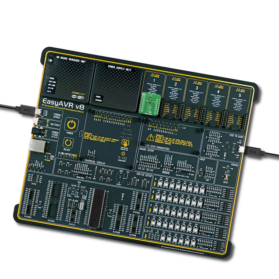
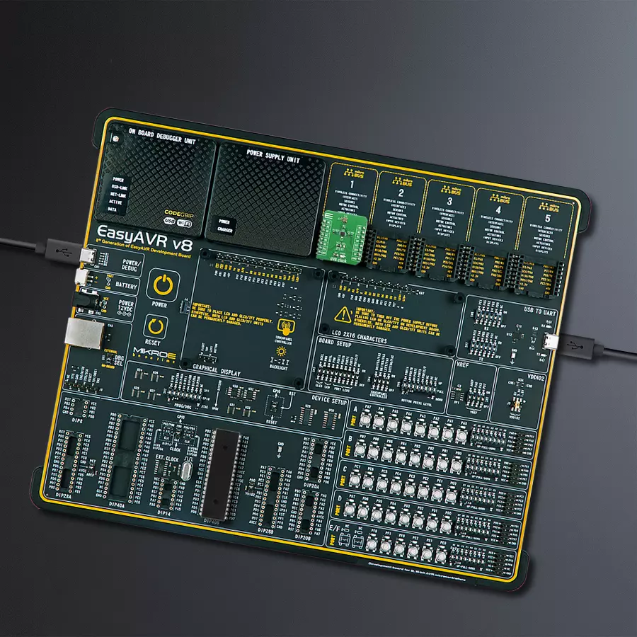
Development board
EasyAVR v8 is a development board designed to rapidly develop embedded applications based on 8-bit AVR microcontrollers (MCUs). Redesigned from the ground up, EasyAVR v8 offers a familiar set of standard features, as well as some new and unique features standard for the 8th generation of development boards: programming and debugging over the WiFi network, connectivity provided by USB-C connectors, support for a wide range of different MCUs, and more. The development board is designed so that the developer has everything that might be needed for the application development, following the Swiss Army knife concept: a highly advanced programmer/debugger module, a reliable power supply module, and a USB-UART connectivity option. EasyAVR v8 board offers several different DIP sockets, covering a wide range of 8-bit AVR MCUs, from the smallest
AVR MCU devices with only eight pins, all the way up to 40-pin "giants". The development board supports the well-established mikroBUS™ connectivity standard, offering five mikroBUS™ sockets, allowing access to a huge base of Click boards™. EasyAVR v8 offers two display options, allowing even the basic 8-bit AVR MCU devices to utilize them and display graphical or textual content. One of them is the 1x20 graphical display connector, compatible with the familiar Graphical Liquid Crystal Display (GLCD) based on the KS108 (or compatible) display driver, and EasyTFT board that contains TFT Color Display MI0283QT-9A, which is driven by ILI9341 display controller, capable of showing advanced graphical content. The other option is the 2x16 character LCD module, a four-bit display module with an embedded character-based display controller. It
requires minimal processing power from the host MCU for its operation. There is a wide range of useful interactive options at the disposal: high-quality buttons with selectable press levels, LEDs, pull-up/pulldown DIP switches, and more. All these features are packed on a single development board, which uses innovative manufacturing technologies, delivering a fluid and immersive working experience. The EasyAVR v8 development board is also integral to the MIKROE rapid development ecosystem. Natively supported by the MIKROE Software toolchain, backed up by hundreds of different Click board™ designs with their number growing daily, it covers many different prototyping and development aspects, thus saving precious development time.

Microcontroller Overview
MCU Card / MCU

Architecture
AVR
MCU Memory (KB)
128
Silicon Vendor
Microchip
Pin count
40
RAM (Bytes)
16384
Used MCU Pins
mikroBUS™ mapper
Take a closer look
Click board™ Schematic

Step by step
Project assembly

Start by selecting your development board and Click board™. Begin with the EasyAVR v8 as your development board.


Track your results in real time
Application Output
1. Application Output - In Debug mode, the 'Application Output' window enables real-time data monitoring, offering direct insight into execution results. Ensure proper data display by configuring the environment correctly using the provided tutorial.

2. UART Terminal - Use the UART Terminal to monitor data transmission via a USB to UART converter, allowing direct communication between the Click board™ and your development system. Configure the baud rate and other serial settings according to your project's requirements to ensure proper functionality. For step-by-step setup instructions, refer to the provided tutorial.

3. Plot Output - The Plot feature offers a powerful way to visualize real-time sensor data, enabling trend analysis, debugging, and comparison of multiple data points. To set it up correctly, follow the provided tutorial, which includes a step-by-step example of using the Plot feature to display Click board™ readings. To use the Plot feature in your code, use the function: plot(*insert_graph_name*, variable_name);. This is a general format, and it is up to the user to replace 'insert_graph_name' with the actual graph name and 'variable_name' with the parameter to be displayed.

Software Support
Library Description
This library contains API for UVB Click driver.
Key functions:
uvb_configuration- Configuration registeruvb_read_byte- Read one byte data from registeruvb_get_uv_data- Get UVB data
Open Source
Code example
The complete application code and a ready-to-use project are available through the NECTO Studio Package Manager for direct installation in the NECTO Studio. The application code can also be found on the MIKROE GitHub account.
/*!
 * @file main.c
 * @brief UVB Click example
 *
 * # Description
 * This Click is ultraviolet sensing board, capable of measuring UV index between 0 to 16.
 * UVB Click supports integrated functions of ultraviolet light sensors.
 *
 * The demo application is composed of two sections :
 *
 * ## Application Init
 * Initialization driver init, check communication and configuration module for measurement.
 *
 * ## Application Task
 * Reads UVB data and logs to the USBUART every 1500ms.
 *
 * @author Mikroe Team
 *
 */

#include "board.h"
#include "log.h"
#include "uvb.h"

static uvb_t uvb;
static log_t logger;

static uint16_t uvb_data;

void application_init ( void )
{
    log_cfg_t log_cfg;  /**< Logger config object. */
    uvb_cfg_t uvb_cfg;  /**< Click config object. */

    /**
     * Logger initialization.
     * Default baud rate: 115200
     * Default log level: LOG_LEVEL_DEBUG
     * @note If USB_UART_RX and USB_UART_TX
     * are defined as HAL_PIN_NC, you will
     * need to define them manually for log to work.
     * See @b LOG_MAP_USB_UART macro definition for detailed explanation.
     */
    LOG_MAP_USB_UART( log_cfg );
    log_init( &logger, &log_cfg );
    log_info( &logger, " Application Init " );

    // Click initialization.
    uvb_cfg_setup( &uvb_cfg );
    UVB_MAP_MIKROBUS( uvb_cfg, MIKROBUS_1 );
    err_t init_flag = uvb_init( &uvb, &uvb_cfg );
    if ( I2C_MASTER_ERROR == init_flag ) {
        log_error( &logger, " Application Init Error. " );
        log_info( &logger, " Please, run program again... " );

        for ( ; ; );
    }

    uvb_default_cfg ( &uvb );
    log_info( &logger, " Application Task " );
    log_printf( &logger, "--------------------------\r\n" );
}

void application_task ( void )
{
    uvb_data = uvb_get_uv_data( &uvb );

    log_printf( &logger, ">> UVB data: %d\r\n", uvb_data );

    log_printf( &logger, "--------------------------\r\n" );
    Delay_ms ( 1000 );
    Delay_ms ( 500 );
}

int main ( void )
{
    /* Do not remove this line or clock might not be set correctly. */
    #ifdef PREINIT_SUPPORTED
    preinit();
    #endif

    application_init( );

    for ( ; ; )
    {
        application_task( );
    }

    return 0;
}

// ------------------------------------------------------------------------ END


