Experience the efficiency of our 4-20mA current loop solution with DAC161S997 and STM32F031K6
Enhance your process automation

Published Oct 01, 2024
Click board™
4-20mA T 2 Click
Dev. board
Nucleo 32 with STM32F031K6 MCU
Compiler
NECTO Studio
MCU
STM32F031K6
Experience precise signal transmission with our advanced analog current loop transmitter, which provides seamless connectivity and compatibility with various industrial applications
A
A
Hardware Overview
How does it work?
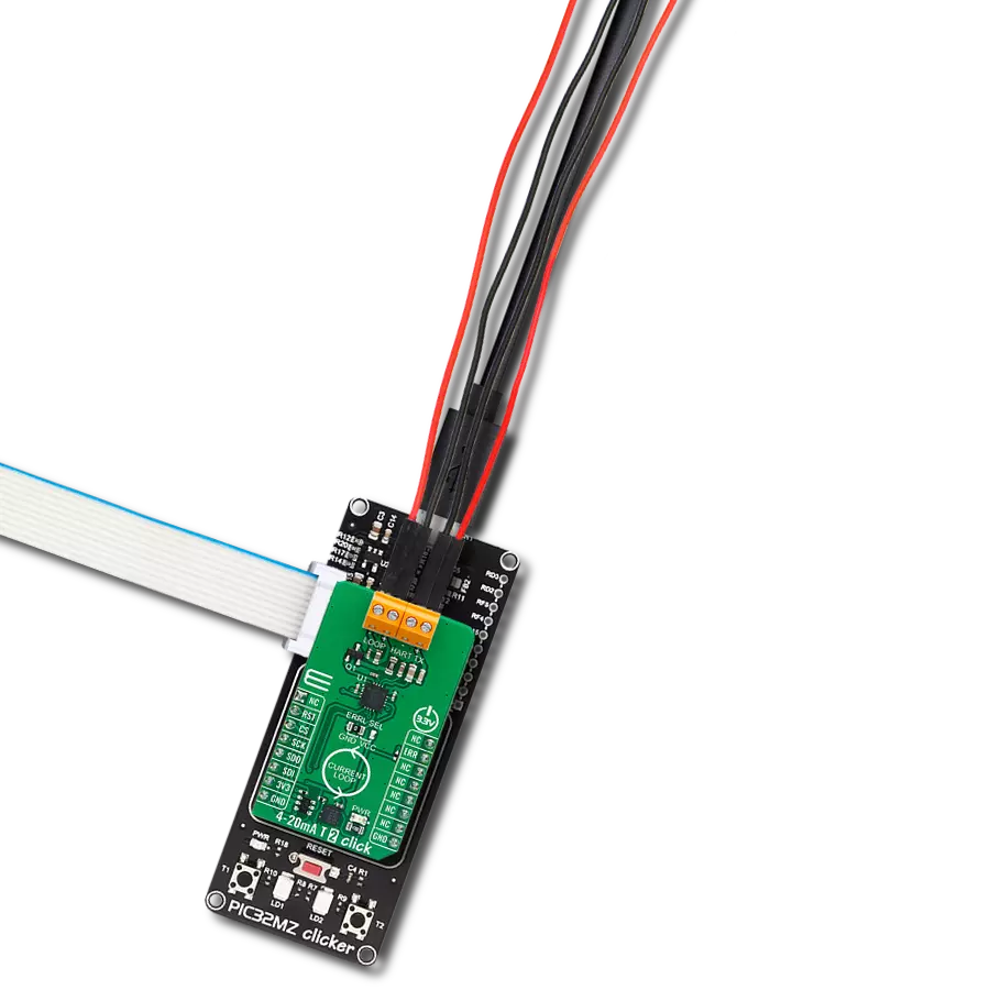
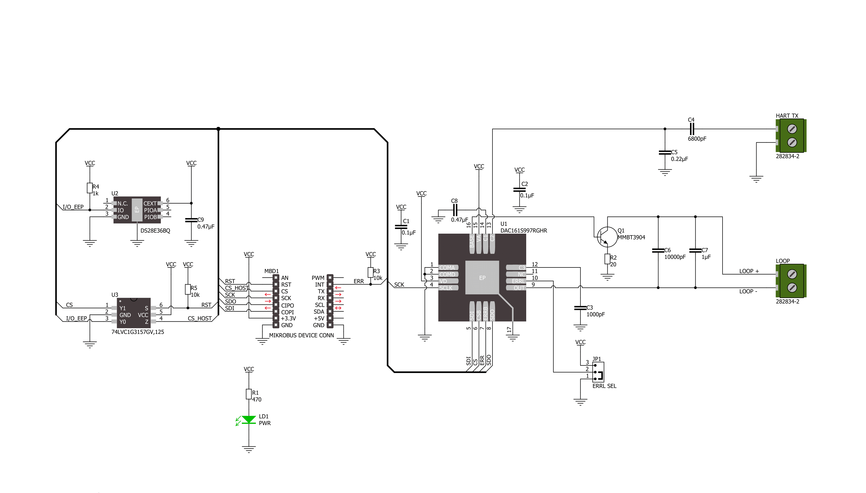
4-20mA T 2 Click is based on the DAC161S997, a low-power 16-bit ΣΔ digital-to-analog converter (DAC) from Texas Instruments, realized as a ΣΔ modulator. Next to ΣΔ DAC, the DAC161S997 also contains an internal ultra-low power voltage reference and an internal oscillator to reduce power and component count in compact loop-powered applications. This architecture, where DAC's output current represents a multiplied copy of the filtered modulator output, ensures an excellent linearity performance while minimizing the device's power consumption. In addition to an industry-standard 4-20 mA current loop over the LOOP terminal, the DAC161S997 also has the possibility of a simple Highway Addressable
Remote Transducer (HART) modulator interfacing through an onboard HART TX terminal. It allows the injection of FSK-modulated digital data into the 4-20mA current loop. This Click board™ communicates with MCU using a 4-wire SPI serial interface with a maximum frequency of 10MHz, for data transfer and configuration of the DAC functions. The DAC161S997 supports both Mode 0 and Mode 3 of the SPI protocol. 4-20mA T 2 Click comes with an additional feature, as an interrupt, available on the ERR pin of the mikroBUS™ socket, the loop-error detection/reporting feature. By default, the DAC161S997 detects and reports several types of errors: loop error, SPI timeout error (channel error), frame error, and alarm current. In
the case of a fault condition or during the initial Power-Up sequence, the DAC161S997 will output current in either the upper or lower error current band. The band's choice is user-selectable via the appropriate position of an onboard jumper ERRL SEL, while the current error value is programmable through the SPI interface. This Click board™ can be operated only with a 3.3V logic voltage level. The board must perform appropriate logic voltage level conversion before using MCUs with different logic levels. Also, it comes equipped with a library containing functions and an example code that can be used, as a reference, for further development.

Features overview
Development board
Nucleo 32 with STM32F031K6 MCU board provides an affordable and flexible platform for experimenting with STM32 microcontrollers in 32-pin packages. Featuring Arduino™ Nano connectivity, it allows easy expansion with specialized shields, while being mbed-enabled for seamless integration with online resources. The
board includes an on-board ST-LINK/V2-1 debugger/programmer, supporting USB reenumeration with three interfaces: Virtual Com port, mass storage, and debug port. It offers a flexible power supply through either USB VBUS or an external source. Additionally, it includes three LEDs (LD1 for USB communication, LD2 for power,
and LD3 as a user LED) and a reset push button. The STM32 Nucleo-32 board is supported by various Integrated Development Environments (IDEs) such as IAR™, Keil®, and GCC-based IDEs like AC6 SW4STM32, making it a versatile tool for developers.

Microcontroller Overview
MCU Card / MCU

Architecture
ARM Cortex-M0
MCU Memory (KB)
32
Silicon Vendor
STMicroelectronics
Pin count
32
RAM (Bytes)
4096
You complete me!
Accessories
Click Shield for Nucleo-32 is the perfect way to expand your development board's functionalities with STM32 Nucleo-32 pinout. The Click Shield for Nucleo-32 provides two mikroBUS™ sockets to add any functionality from our ever-growing range of Click boards™. We are fully stocked with everything, from sensors and WiFi transceivers to motor control and audio amplifiers. The Click Shield for Nucleo-32 is compatible with the STM32 Nucleo-32 board, providing an affordable and flexible way for users to try out new ideas and quickly create prototypes with any STM32 microcontrollers, choosing from the various combinations of performance, power consumption, and features. The STM32 Nucleo-32 boards do not require any separate probe as they integrate the ST-LINK/V2-1 debugger/programmer and come with the STM32 comprehensive software HAL library and various packaged software examples. This development platform provides users with an effortless and common way to combine the STM32 Nucleo-32 footprint compatible board with their favorite Click boards™ in their upcoming projects.

Used MCU Pins
mikroBUS™ mapper
Take a closer look
Click board™ Schematic
Step by step
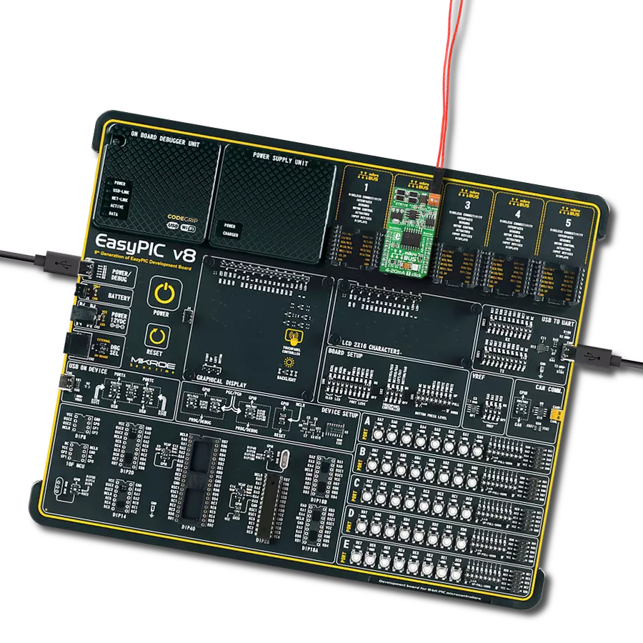
Project assembly

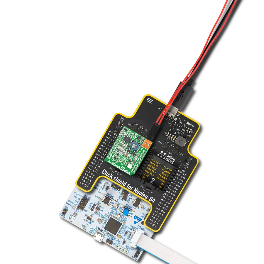
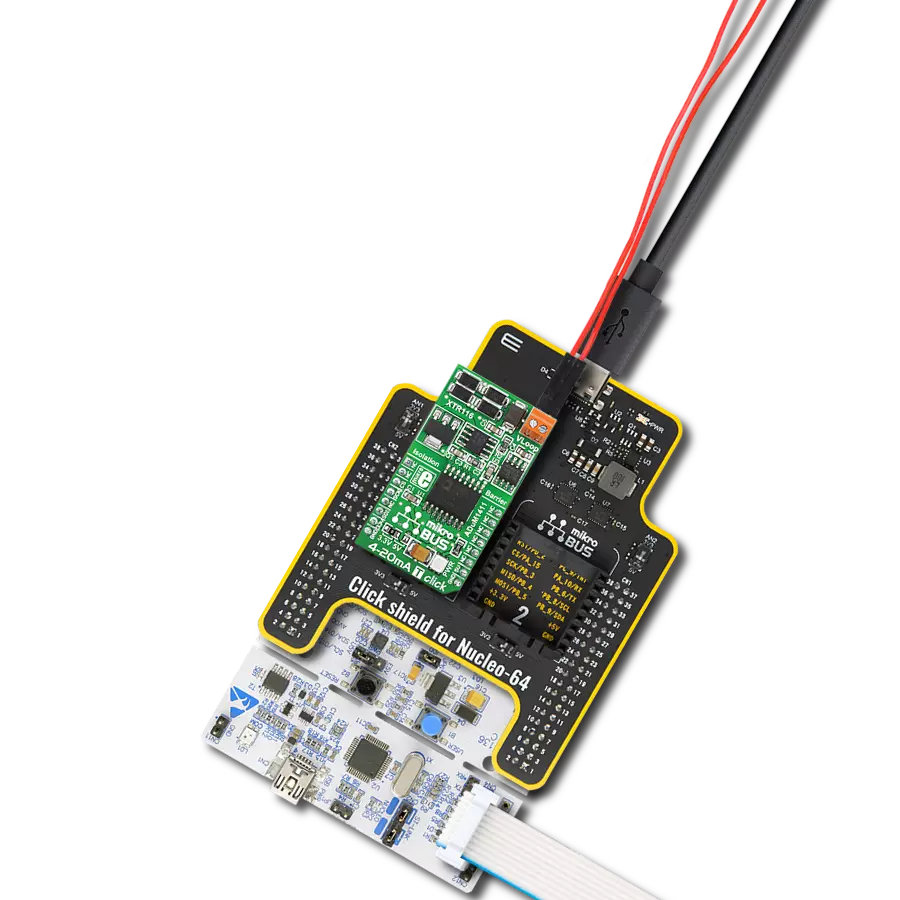
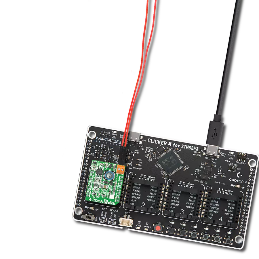
Start by selecting your development board and Click board™. Begin with the Nucleo 32 with STM32F031K6 MCU as your development board.


Track your results in real time
Application Output
1. Application Output - In Debug mode, the 'Application Output' window enables real-time data monitoring, offering direct insight into execution results. Ensure proper data display by configuring the environment correctly using the provided tutorial.

2. UART Terminal - Use the UART Terminal to monitor data transmission via a USB to UART converter, allowing direct communication between the Click board™ and your development system. Configure the baud rate and other serial settings according to your project's requirements to ensure proper functionality. For step-by-step setup instructions, refer to the provided tutorial.

3. Plot Output - The Plot feature offers a powerful way to visualize real-time sensor data, enabling trend analysis, debugging, and comparison of multiple data points. To set it up correctly, follow the provided tutorial, which includes a step-by-step example of using the Plot feature to display Click board™ readings. To use the Plot feature in your code, use the function: plot(*insert_graph_name*, variable_name);. This is a general format, and it is up to the user to replace 'insert_graph_name' with the actual graph name and 'variable_name' with the parameter to be displayed.

Software Support
Library Description
This library contains API for 4-20mA T 2 Click driver.
Key functions:
c420mat2_set_output_current- 4-20mA T 2 set output current functionc420mat2_get_status- 4-20mA T 2 set status functionc420mat2_set_lower_limit- 4-20mA T 2 set lower limit function
Open Source
Code example
The complete application code and a ready-to-use project are available through the NECTO Studio Package Manager for direct installation in the NECTO Studio. The application code can also be found on the MIKROE GitHub account.
/*!
 * @file main.c
 * @brief 4-20mA T 2 Click example
 *
 * # Description
 * This example demonstrates the use of 4-20mA T 2 Click board™.
 * This driver provides functions to configure
 * analog output current transfer over an industry standard 4-20mA current loop.
 *
 * The demo application is composed of two sections :
 *
 * ## Application Init
 * Initialization of SPI module and log UART.
 * After driver initialization, default settings turn on the device.
 *
 * ## Application Task
 * This example demonstrates the use of the 4-20mA T 2 Click board™.
 * This example periodically changes the analog output current transfer
 * from 4mA to 20mA and display status every 5 seconds.
 * Results are being sent to the UART Terminal, where you can track their changes.
 *
 * @author Nenad Filipovic
 *
 */

#include "board.h"
#include "log.h"
#include "c420mat2.h"

static c420mat2_t c420mat2;
static log_t logger;
static c420mat2_status_t status;

void display_status ( void )
{
    log_printf( &logger, " Status: \r\n" );
    if ( C420MAT2_STATUS_ERROR == status.ferr_sts )
    {
        log_printf( &logger, " - A frame error has occurred.\r\n" );
    }
    else
    {
        log_printf( &logger, " - No frame error occurred.\r\n" );
    }

    if ( C420MAT2_STATUS_ERROR == status.spi_timeout_err )
    {
        log_printf( &logger, " - The SPI interface has not received a valid command.\r\n" );
    }
    else
    {
        log_printf( &logger, " - The SPI interface has received a valid command.\r\n" );
    }

    if ( C420MAT2_STATUS_ERROR == status.loop_sts )
    {
        log_printf( &logger, " - A status loop error has occurred.\r\n" );
    }
    else
    {
        log_printf( &logger, " - No status loop error has occurred.\r\n" );
    }

    if ( C420MAT2_STATUS_ERROR == status.curr_loop_sts )
    {
        log_printf( &logger, " - A current loop error is occurring.\r\n" );
    }
    else
    {
        log_printf( &logger, " - No current loop error is occurring.\r\n" );
    }
    log_printf( &logger, " ----------------------------\r\n" );
}

void application_init ( void )
{
    log_cfg_t log_cfg;  /**< Logger config object. */
    c420mat2_cfg_t c420mat2_cfg;  /**< Click config object. */

    /**
     * Logger initialization.
     * Default baud rate: 115200
     * Default log level: LOG_LEVEL_DEBUG
     * @note If USB_UART_RX and USB_UART_TX
     * are defined as HAL_PIN_NC, you will
     * need to define them manually for log to work.
     * See @b LOG_MAP_USB_UART macro definition for detailed explanation.
     */
    LOG_MAP_USB_UART( log_cfg );
    log_init( &logger, &log_cfg );
    log_info( &logger, " Application Init " );

    // Click initialization.
    c420mat2_cfg_setup( &c420mat2_cfg );
    C420MAT2_MAP_MIKROBUS( c420mat2_cfg, MIKROBUS_1 );
    if ( SPI_MASTER_ERROR == c420mat2_init( &c420mat2, &c420mat2_cfg ) )
    {
        log_error( &logger, " Communication init." );
        for ( ; ; );
    }

    if ( C420MAT2_ERROR == c420mat2_default_cfg ( &c420mat2 ) )
    {
        log_error( &logger, " Default configuration." );
        for ( ; ; );
    }

    log_info( &logger, " Application Task " );
    log_printf( &logger, " -----------------------------\r\n" );
    Delay_ms ( 100 );
}

void application_task ( void )
{
    if ( C420MAT2_OK == c420mat2_set_output_current( &c420mat2, 4.0 ) )
    {
        log_printf( &logger, " Loop Current:  4.0 mA \r\n" );
        log_printf( &logger, " - - - - - - - - - - - - - - -\r\n" );
        if ( C420MAT2_OK == c420mat2_get_status ( &c420mat2, &status ) )
        {
            display_status( );
        }
        Delay_ms ( 1000 );
        Delay_ms ( 1000 );
        Delay_ms ( 1000 );
        Delay_ms ( 1000 );
        Delay_ms ( 1000 );
    }

    if ( C420MAT2_OK == c420mat2_set_output_current( &c420mat2, 10.0 ) )
    {
        log_printf( &logger, " Loop Current: 10.0 mA \r\n" );
        log_printf( &logger, " - - - - - - - - - - - - - - -\r\n" );
        if ( C420MAT2_OK == c420mat2_get_status ( &c420mat2, &status ) )
        {
            display_status( );
        }
        Delay_ms ( 1000 );
        Delay_ms ( 1000 );
        Delay_ms ( 1000 );
        Delay_ms ( 1000 );
        Delay_ms ( 1000 );
    }

    if ( C420MAT2_OK == c420mat2_set_output_current( &c420mat2, 15.0 ) )
    {
        log_printf( &logger, " Loop Current: 15.0 mA \r\n" );
        log_printf( &logger, " - - - - - - - - - - - - - - -\r\n" );
        if ( C420MAT2_OK == c420mat2_get_status ( &c420mat2, &status ) )
        {
            display_status( );
        }
        Delay_ms ( 1000 );
        Delay_ms ( 1000 );
        Delay_ms ( 1000 );
        Delay_ms ( 1000 );
        Delay_ms ( 1000 );
    }

    if ( C420MAT2_OK == c420mat2_set_output_current( &c420mat2, 20.0 ) )
    {
        log_printf( &logger, " Loop Current: 20.0 mA \r\n" );
        log_printf( &logger, " - - - - - - - - - - - - - - -\r\n" );
        if ( C420MAT2_OK == c420mat2_get_status ( &c420mat2, &status ) )
        {
            display_status( );
        }
        Delay_ms ( 1000 );
        Delay_ms ( 1000 );
        Delay_ms ( 1000 );
        Delay_ms ( 1000 );
        Delay_ms ( 1000 );
    }
}

int main ( void )
{
    /* Do not remove this line or clock might not be set correctly. */
    #ifdef PREINIT_SUPPORTED
    preinit();
    #endif

    application_init( );

    for ( ; ; )
    {
        application_task( );
    }

    return 0;
}

// ------------------------------------------------------------------------ END
Additional Support
Resources
Category:Current