Show information in a clear and easy-to-read way with LTP-3862 and STM32F031K6
Dual-digit 16-segment alphanumeric green display

Published Oct 01, 2024
Click board™
AlphaNum G 2 Click
Dev. board
Nucleo 32 with STM32F031K6 MCU
Compiler
NECTO Studio
MCU
STM32F031K6
Use a vibrant 16-segment alphanumeric display to illuminate your projects with clear numerical and textual information – perfect for applications that demand visibility and a touch of modern display sophistication
A
A
Hardware Overview
How does it work?
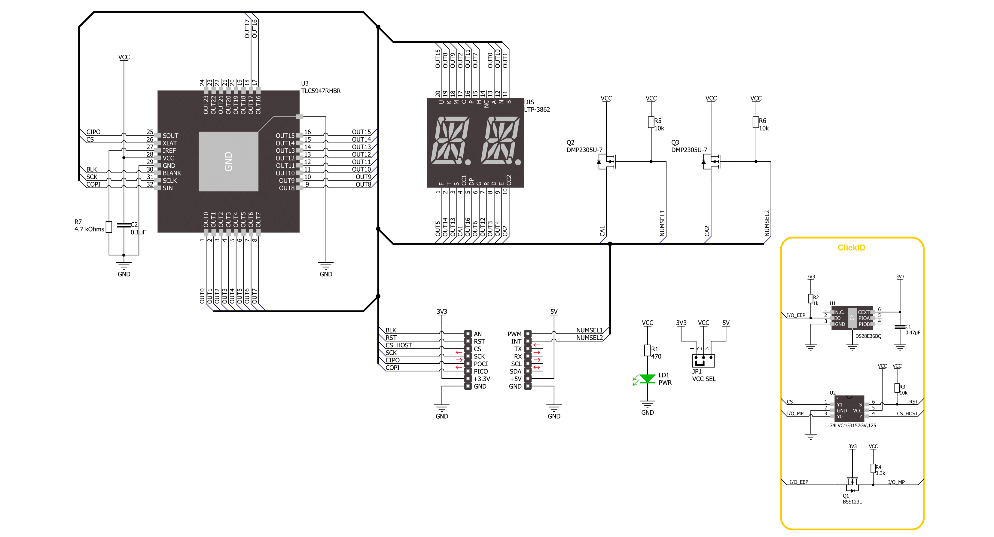
AlphaNum G 2 Click is based on the LTP-3862, a dual-digit 16-segment alphanumeric green display from Lite-ON. It has a 75mW of power disipation per segment. The TLC5947, a 24-channel 12-bit PWM LED driver from Texas Instruments, drives all these LED segments. It is a constant current sink LED driver with adjustable 4096 pulse width modulation (PWM) on each channel individually. The PWM control is repeated automatically with the programmed grayscale data. An external resistor sets the constant current to around 10mA.
The LED driver features thermal shutdown, auto display repeat, noise reduction, and more. AlphaNum G 2 Click uses a standard 4-Wire SPI serial interface to communicate with the host MCU, supporting a clock frequency of up to 30MHz. A Blank BLK pin can turn all constant current outputs OFF while initializing the grayscale PWM timing. This can be achieved by writing the High logic state on the Blank pin. You can also turn off every display separately, no matter the LED driver IC, over the CA1 and CA2
pins. These pins control the common anode pins of the displays. This Click board™ can operate with either 3.3V or 5V logic voltage levels selected via the VCC SEL jumper. This way, both 3.3V and 5V capable MCUs can use the communication lines properly. Also, this Click board™ comes equipped with a library containing easy-to-use functions and an example code that can be used as a reference for further development.

Features overview
Development board
Nucleo 32 with STM32F031K6 MCU board provides an affordable and flexible platform for experimenting with STM32 microcontrollers in 32-pin packages. Featuring Arduino™ Nano connectivity, it allows easy expansion with specialized shields, while being mbed-enabled for seamless integration with online resources. The
board includes an on-board ST-LINK/V2-1 debugger/programmer, supporting USB reenumeration with three interfaces: Virtual Com port, mass storage, and debug port. It offers a flexible power supply through either USB VBUS or an external source. Additionally, it includes three LEDs (LD1 for USB communication, LD2 for power,
and LD3 as a user LED) and a reset push button. The STM32 Nucleo-32 board is supported by various Integrated Development Environments (IDEs) such as IAR™, Keil®, and GCC-based IDEs like AC6 SW4STM32, making it a versatile tool for developers.

Microcontroller Overview
MCU Card / MCU

Architecture
ARM Cortex-M0
MCU Memory (KB)
32
Silicon Vendor
STMicroelectronics
Pin count
32
RAM (Bytes)
4096
You complete me!
Accessories
Click Shield for Nucleo-32 is the perfect way to expand your development board's functionalities with STM32 Nucleo-32 pinout. The Click Shield for Nucleo-32 provides two mikroBUS™ sockets to add any functionality from our ever-growing range of Click boards™. We are fully stocked with everything, from sensors and WiFi transceivers to motor control and audio amplifiers. The Click Shield for Nucleo-32 is compatible with the STM32 Nucleo-32 board, providing an affordable and flexible way for users to try out new ideas and quickly create prototypes with any STM32 microcontrollers, choosing from the various combinations of performance, power consumption, and features. The STM32 Nucleo-32 boards do not require any separate probe as they integrate the ST-LINK/V2-1 debugger/programmer and come with the STM32 comprehensive software HAL library and various packaged software examples. This development platform provides users with an effortless and common way to combine the STM32 Nucleo-32 footprint compatible board with their favorite Click boards™ in their upcoming projects.

Used MCU Pins
mikroBUS™ mapper
Take a closer look
Click board™ Schematic
Step by step
Project assembly

Start by selecting your development board and Click board™. Begin with the Nucleo 32 with STM32F031K6 MCU as your development board.


Software Support
Library Description
This library contains API for AlphaNum G 2 Click driver.
Key functions:
alphanumg2_display_character- AlphaNum G 2 display character function.alphanumg2_set_led_output- AlphaNum G 2 set LED output function.
Open Source
Code example
The complete application code and a ready-to-use project are available through the NECTO Studio Package Manager for direct installation in the NECTO Studio. The application code can also be found on the MIKROE GitHub account.
/*!
 * @file main.c
 * @brief AlphaNum G 2 Click example
 *
 * # Description
 * This example demonstrates the use of the AlphaNum G 2 Click board™
 * by writing and displaying the desired alphanumeric characters.
 *
 * The demo application is composed of two sections :
 *
 * ## Application Init
 * Initialization of SPI module and log UART.
 * After driver initialization, the app executes a default configuration.
 *
 * ## Application Task
 * The demo application displays digits from '0' to '9',
 * symbols: colon, semicolon, less-than, equals-to, greater-than, question mark, at sign
 * and capital alphabet letters, on both alphanumeric segments of the Click.
 * Results are being sent to the UART Terminal, where you can track their changes.
 *
 * @author Nenad Filipovic
 *
 */

#include "board.h"
#include "log.h"
#include "alphanumg2.h"

#define ASCII_CHARACTER_DIGIT_0        '0'
#define ASCII_CHARACTER_UPPERCASE_Z    'Z'

static alphanumg2_t alphanumg2;
static log_t logger;
static uint8_t character = ASCII_CHARACTER_DIGIT_0;

void application_init ( void )
{
    log_cfg_t log_cfg;  /**< Logger config object. */
    alphanumg2_cfg_t alphanumg2_cfg;  /**< Click config object. */

    /**
     * Logger initialization.
     * Default baud rate: 115200
     * Default log level: LOG_LEVEL_DEBUG
     * @note If USB_UART_RX and USB_UART_TX
     * are defined as HAL_PIN_NC, you will
     * need to define them manually for log to work.
     * See @b LOG_MAP_USB_UART macro definition for detailed explanation.
     */
    LOG_MAP_USB_UART( log_cfg );
    log_init( &logger, &log_cfg );
    log_info( &logger, " Application Init " );

    // Click initialization.
    alphanumg2_cfg_setup( &alphanumg2_cfg );
    ALPHANUMG2_MAP_MIKROBUS( alphanumg2_cfg, MIKROBUS_1 );
    if ( SPI_MASTER_ERROR == alphanumg2_init( &alphanumg2, &alphanumg2_cfg ) )
    {
        log_error( &logger, " Communication init." );
        for ( ; ; );
    }

    if ( ALPHANUMG2_ERROR == alphanumg2_default_cfg ( &alphanumg2 ) )
    {
        log_error( &logger, " Default configuration." );
        for ( ; ; );
    }

    log_info( &logger, " Application Task " );
    log_printf( &logger, "------------------------\r\n" );
    Delay_ms ( 100 );
}

void application_task ( void )
{
    log_printf( &logger, " %c %c\r\n", character, character + 1 );
    if ( ALPHANUMG2_OK == alphanumg2_display_character( &alphanumg2,
                                                        character, ALPHANUMG2_BRIGHTNESS_MAX,
                                                        character + 1, ALPHANUMG2_BRIGHTNESS_MAX ) )
    {
        character++;
        if ( ASCII_CHARACTER_UPPERCASE_Z <= character )
        {
            character = ASCII_CHARACTER_DIGIT_0;
            log_printf( &logger, "------------------------\r\n" );
            Delay_ms ( 1000 );
        }
    }
}

int main ( void )
{
    /* Do not remove this line or clock might not be set correctly. */
    #ifdef PREINIT_SUPPORTED
    preinit();
    #endif

    application_init( );

    for ( ; ; )
    {
        application_task( );
    }

    return 0;
}

// ------------------------------------------------------------------------ END
Additional Support
Resources
Category:LED Segment


