Experience the voltage step-down elegance with BMR4613001/001 and STM32F031K6
Synchronous step-down beast!
Published Oct 01, 2024
Click board™
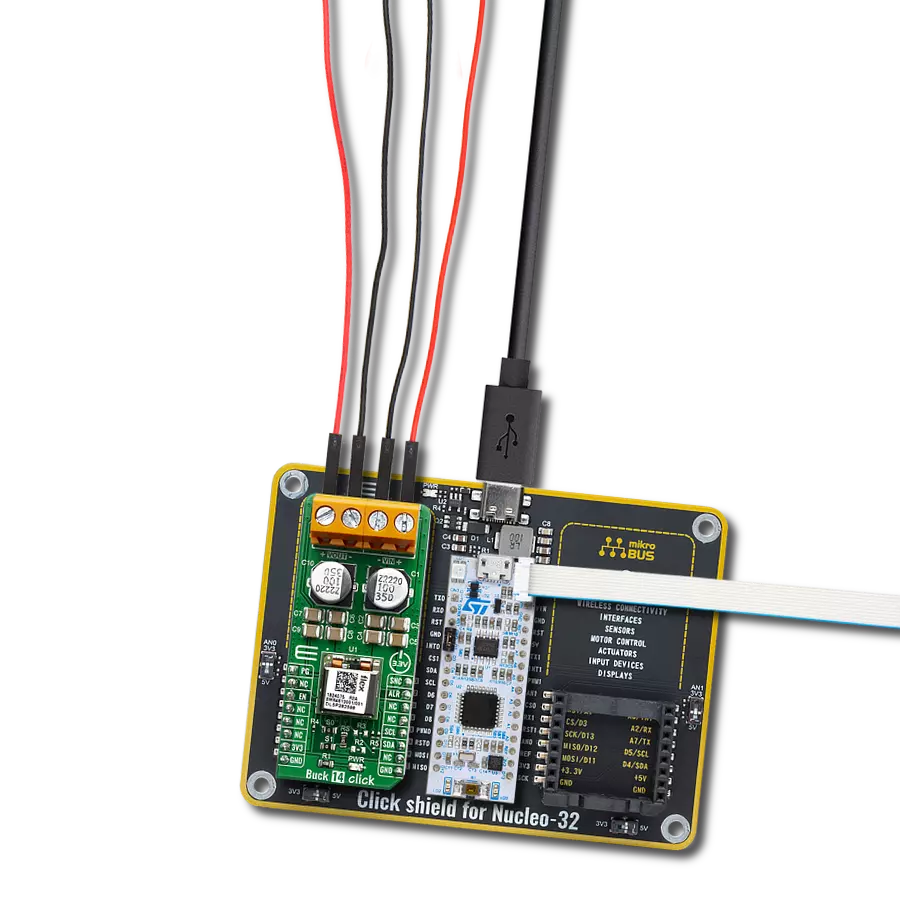
Buck 14 Click
Dev. board
Nucleo 32 with STM32F031K6 MCU
Compiler
NECTO Studio
MCU
STM32F031K6
Through its ability to step down voltages with exceptional efficiency, our buck converter also contributes to a greener and more sustainable future by conserving energy resources
A
A
Hardware Overview
How does it work?
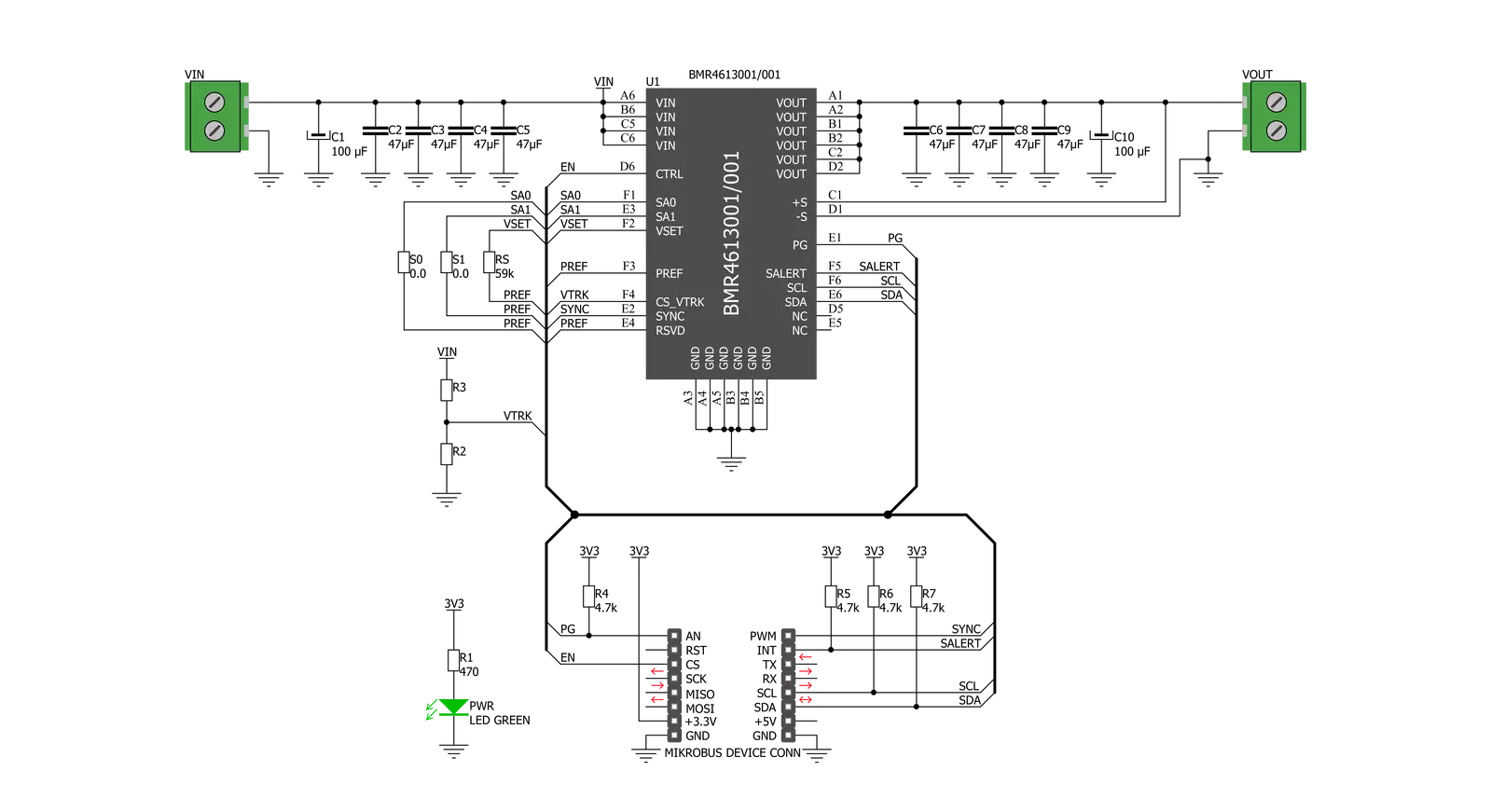
Buck 14 Click is based on the BMR4613001/001 - a PoL regulator from Flex that incorporates a wide range of readable and configurable power management features that are simple to implement with a minimum of external components. Additionally, it includes protection features that continuously safeguard the load from damage due to unexpected system faults. A fault is also shown as an alert on the ALR pin of the mikroBUS™ socket. The product is delivered with a default configuration suitable for various operations regarding input voltage, output voltage, and load. The configuration is stored in an internal Non-Volatile Memory (NVM). All power management functions can be reconfigured using the PMBus interface. It is possible to monitor various parameters through the PMBus interface. Fault conditions can be monitored using the
ALERT pin, which will be asserted when any pre-configured fault or warning conditions occur. The Buck 14 click supports tracking the output from a master voltage applied to the VTRK pin of BMR4613001/001. To select the tracking mode, a resistance ≤ 4.22 kΩ must be connected between the VSET and PREF pins (RS resistor). The tracking ratio is controlled by an internal feedback divider RDIV and an external resistive voltage divider (R3, R2, not populated on the board) placed from the supply being tracked to GND pins. Unlike PID-based digital power regulators, the product uses a state-space model-based algorithm valid for both the small- and large-signal response and accounts for duty-cycle saturation effects. This eliminates the need for users to determine and set thresholds for transitioning from linear to nonlinear modes. These capabilities result in a fast loop transient
response and the possibility of reducing the number of output capacitors. The product features a remote control input through the EN pin and a PMBus enable function by the command OPERATION to control the output voltage. It is also possible to configure the output to be always on. By default, the output is controlled by the EN pin only. The output voltage control can be reconfigured using the PMBus command ON_OFF_CONFIG. It is designed to operate in different thermal environments, and sufficient cooling must ensure reliable operation. Cooling is achieved mainly by conduction, from the pins to the host board, and convection, which depends on the product's airflow. Increased airflow enhances the cooling of the product.

Features overview
Development board
Nucleo 32 with STM32F031K6 MCU board provides an affordable and flexible platform for experimenting with STM32 microcontrollers in 32-pin packages. Featuring Arduino™ Nano connectivity, it allows easy expansion with specialized shields, while being mbed-enabled for seamless integration with online resources. The
board includes an on-board ST-LINK/V2-1 debugger/programmer, supporting USB reenumeration with three interfaces: Virtual Com port, mass storage, and debug port. It offers a flexible power supply through either USB VBUS or an external source. Additionally, it includes three LEDs (LD1 for USB communication, LD2 for power,
and LD3 as a user LED) and a reset push button. The STM32 Nucleo-32 board is supported by various Integrated Development Environments (IDEs) such as IAR™, Keil®, and GCC-based IDEs like AC6 SW4STM32, making it a versatile tool for developers.

Microcontroller Overview
MCU Card / MCU

Architecture
ARM Cortex-M0
MCU Memory (KB)
32
Silicon Vendor
STMicroelectronics
Pin count
32
RAM (Bytes)
4096
You complete me!
Accessories
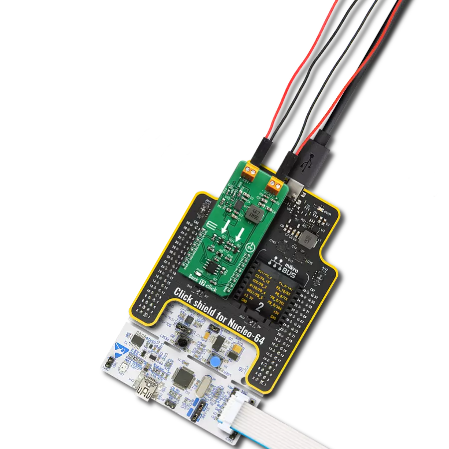
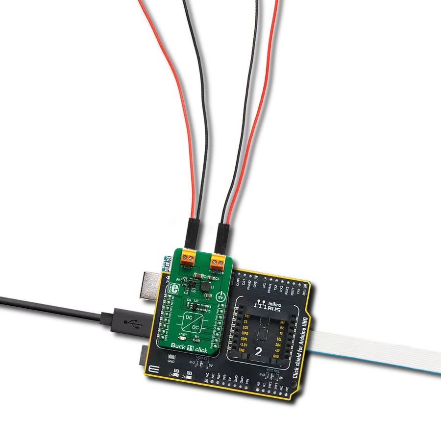
Click Shield for Nucleo-32 is the perfect way to expand your development board's functionalities with STM32 Nucleo-32 pinout. The Click Shield for Nucleo-32 provides two mikroBUS™ sockets to add any functionality from our ever-growing range of Click boards™. We are fully stocked with everything, from sensors and WiFi transceivers to motor control and audio amplifiers. The Click Shield for Nucleo-32 is compatible with the STM32 Nucleo-32 board, providing an affordable and flexible way for users to try out new ideas and quickly create prototypes with any STM32 microcontrollers, choosing from the various combinations of performance, power consumption, and features. The STM32 Nucleo-32 boards do not require any separate probe as they integrate the ST-LINK/V2-1 debugger/programmer and come with the STM32 comprehensive software HAL library and various packaged software examples. This development platform provides users with an effortless and common way to combine the STM32 Nucleo-32 footprint compatible board with their favorite Click boards™ in their upcoming projects.

Used MCU Pins
mikroBUS™ mapper
Take a closer look
Click board™ Schematic
Step by step
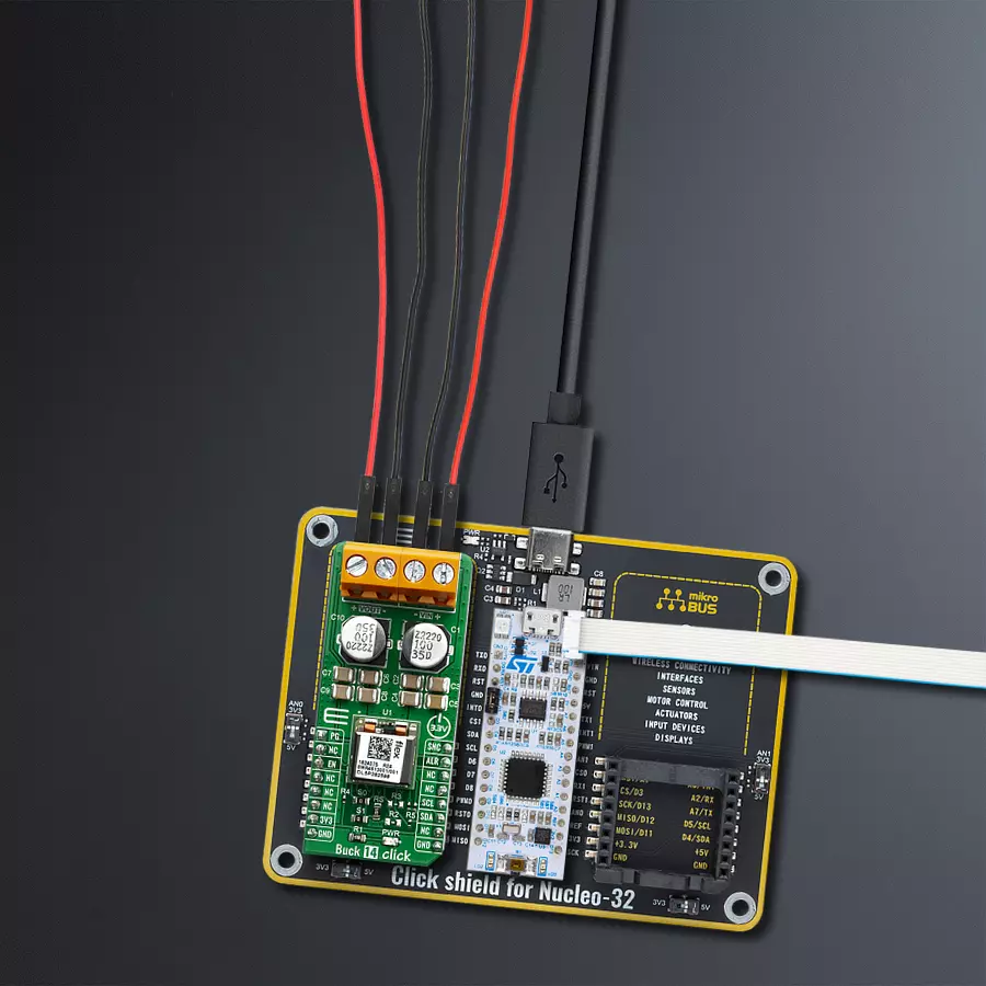
Project assembly

Start by selecting your development board and Click board™. Begin with the Nucleo 32 with STM32F031K6 MCU as your development board.


Track your results in real time
Application Output
1. Application Output - In Debug mode, the 'Application Output' window enables real-time data monitoring, offering direct insight into execution results. Ensure proper data display by configuring the environment correctly using the provided tutorial.

2. UART Terminal - Use the UART Terminal to monitor data transmission via a USB to UART converter, allowing direct communication between the Click board™ and your development system. Configure the baud rate and other serial settings according to your project's requirements to ensure proper functionality. For step-by-step setup instructions, refer to the provided tutorial.

3. Plot Output - The Plot feature offers a powerful way to visualize real-time sensor data, enabling trend analysis, debugging, and comparison of multiple data points. To set it up correctly, follow the provided tutorial, which includes a step-by-step example of using the Plot feature to display Click board™ readings. To use the Plot feature in your code, use the function: plot(*insert_graph_name*, variable_name);. This is a general format, and it is up to the user to replace 'insert_graph_name' with the actual graph name and 'variable_name' with the parameter to be displayed.

Software Support
Library Description
This library contains API for Buck 14 Click driver.
Key functions:
buck14_power_ctrl- This function sets state of the power control pinbuck14_salert- This function gets manufacturer IDbuc14_write_vout- This function sets output voltage
Open Source
Code example
The complete application code and a ready-to-use project are available through the NECTO Studio Package Manager for direct installation in the NECTO Studio. The application code can also be found on the MIKROE GitHub account.
/*!
 * \file
 * \brief Buck14 Click example
 *
 * # Description
 * This app enables usage of high-efficiency step-down converter.
 *
 * The demo application is composed of two sections :
 *
 * ## Application Init
 * Configure device.
 *
 * ## Application Task
 * Sends 4 different commands for VOUT in span of 8sec
 *
 * *note:*
 * When you send data you should send LSB first.
 * Device input V should be beetween 4.5 - 14 V.
 * Device output V could be from 0.5 - 5 V deepending from limits you set currently it is set to 1V.
 *
 * \author MikroE Team
 *
 */
// ------------------------------------------------------------------- INCLUDES

#include "board.h"
#include "log.h"
#include "buck14.h"

// ------------------------------------------------------------------ VARIABLES

static buck14_t buck14;
static log_t logger;

// ------------------------------------------------------- ADDITIONAL FUNCTIONS

void error_handler ( uint8_t stat_data )
{
    if ( stat_data == BUCK14_ERROR )
    {
        log_printf( &logger, "ERROR! \r\n " );
        for ( ; ; );
    }
    else if ( stat_data == BUCK14_ID_ERROR )
    {
        log_printf( &logger, "ID ERROR! \r\n " );
        for ( ; ; );
    }
    else if ( stat_data == BUCK14_CMD_ERROR )
    {
        log_printf( &logger, "CMD ERROR! \r\n " );
    }
}

void read_vout_data ( buck14_t *ctx )
{
    uint16_t temp_data;

    temp_data = buc14_read_vout( &buck14 );
    log_printf( &logger, "VOUT ~ %u mV \r\n", temp_data );
}

// ------------------------------------------------------ APPLICATION FUNCTIONS

void application_init ( void )
{
    log_cfg_t log_cfg;
    buck14_cfg_t cfg;
    uint8_t write_data;
    uint8_t status_data;

    /**
     * Logger initialization.
     * Default baud rate: 115200
     * Default log level: LOG_LEVEL_DEBUG
     * @note If USB_UART_RX and USB_UART_TX
     * are defined as HAL_PIN_NC, you will
     * need to define them manually for log to work.
     * See @b LOG_MAP_USB_UART macro definition for detailed explanation.
     */
    LOG_MAP_USB_UART( log_cfg );
    log_init( &logger, &log_cfg );
    log_info( &logger, "---- Application Init ----" );

    //  Click initialization.

    buck14_cfg_setup( &cfg );
    BUCK14_MAP_MIKROBUS( cfg, MIKROBUS_1 );
    buck14_init( &buck14, &cfg );

    buck14_reset( &buck14 );

    write_data  = BUCK14_CTRL_ENABLE_NO_MARGIN;
    buck14_generic_write( &buck14, BUCK14_CMD_OPERATION, &write_data , 1 );
    Delay_ms ( 300 );

    status_data = buck14_check_mfr_id(  &buck14 );
    error_handler( status_data );
    log_printf( &logger, "-Device ID OK!\r\n" );

    buck14_power_ctrl( &buck14, BUCK14_PIN_STATE_HIGH );

    buck14_default_cfg( &buck14 );
    log_printf( &logger, " ***** App init ***** \r\n" );
    log_printf( &logger, "----------------------\r\n" );
    Delay_ms ( 100 );
}

void application_task ( void )
{
    uint8_t status_data;
    float vout_value;

    vout_value = 1.2;
    status_data = buc14_write_vout( &buck14, vout_value );
    error_handler( status_data );

    if ( status_data == BUCK14_SUCCESSFUL )
    {
        read_vout_data(  &buck14 );
    }
    // 8 seconds delay
    Delay_ms ( 1000 );
    Delay_ms ( 1000 );
    Delay_ms ( 1000 );
    Delay_ms ( 1000 );
    Delay_ms ( 1000 );
    Delay_ms ( 1000 );
    Delay_ms ( 1000 );
    Delay_ms ( 1000 );

    vout_value = 3.7;
    status_data = buc14_write_vout( &buck14, vout_value );
    error_handler( status_data );

    if ( status_data == BUCK14_SUCCESSFUL )
    {
        read_vout_data( &buck14 );
    }

    // 8 seconds delay
    Delay_ms ( 1000 );
    Delay_ms ( 1000 );
    Delay_ms ( 1000 );
    Delay_ms ( 1000 );
    Delay_ms ( 1000 );
    Delay_ms ( 1000 );
    Delay_ms ( 1000 );
    Delay_ms ( 1000 );

    vout_value = 2.5;
    status_data = buc14_write_vout( &buck14, vout_value );
    error_handler( status_data );

    if ( status_data == BUCK14_SUCCESSFUL )
    {
        read_vout_data(  &buck14 );
    }

    // 8 seconds delay
    Delay_ms ( 1000 );
    Delay_ms ( 1000 );
    Delay_ms ( 1000 );
    Delay_ms ( 1000 );
    Delay_ms ( 1000 );
    Delay_ms ( 1000 );
    Delay_ms ( 1000 );
    Delay_ms ( 1000 );

    vout_value = 4.5;
    status_data = buc14_write_vout(  &buck14, vout_value );
    error_handler( status_data );

    if ( status_data == BUCK14_SUCCESSFUL )
    {
        read_vout_data(  &buck14 );
    }

    Delay_ms ( 1000 );
    Delay_ms ( 1000 );
    Delay_ms ( 1000 );
    Delay_ms ( 1000 );
    log_printf( &logger, "```````````````\r\n" );
    Delay_ms ( 1000 );
    Delay_ms ( 1000 );
    Delay_ms ( 1000 );
    Delay_ms ( 1000 );
}

int main ( void )
{
    /* Do not remove this line or clock might not be set correctly. */
    #ifdef PREINIT_SUPPORTED
    preinit();
    #endif

    application_init( );

    for ( ; ; )
    {
        application_task( );
    }

    return 0;
}

// ------------------------------------------------------------------------ END