Experience seamless buck-boost power control with MIC7401 and STM32F031K6
Master the art of voltage regulation
Published Oct 01, 2024
Click board™
Buck & Boost Click
Dev. board
Nucleo 32 with STM32F031K6 MCU
Compiler
NECTO Studio
MCU
STM32F031K6
Achieve exceptional load regulation, ensuring stable output voltage under varying load conditions for precision-driven applications
A
A
Hardware Overview
How does it work?
Buck & Boost Click is based on the MIC7401, a powerful highly-integrated configurable power management (PMIC) featuring buck and boost regulators and a high-speed I2C interface with an internal EEPROM memory and micro-power shutdown function from Microchip. This Click board™ has five 3A synchronous buck regulators with high-speed adaptive on-time control and one boost regulator that provides a flash-memory programming supply that delivers up to 200mA of output current. The boost has an output disconnect switch that opens if a short-to-ground fault is detected. The MIC7401 offers two distinct modes of operation, Standby, and Normal mode, intended to provide an energy-optimized solution suitable for portable handheld and infotainment applications. In Normal mode, the programmable switching converters can be configured to support
a variety of Start-up sequencing, timing, soft-start ramp, output voltage levels, current limit levels, and output discharge for each channel. In Standby mode, this PMIC can be configured in a low-power state by turning off the output or changing the output voltage to a lower level. Independent exit from Standby mode can be achieved by I2C communication or the STB pin of the mikroBUS™ socket. Buck & Boost Click communicates with MCU using the standard I2C 2-Wire interface with a frequency of up to 100kHz in the Standard, up to 400 kHz in the Fast, and up to 3.4MHz in the High-Speed mode. This Click board™ also contains additional functionalities routed to the CS, AN, PWM, and INT pins on the mikroBUS™ socket. CS pin labeled EN represents an enable pin that shuts down the device for additional power savings. The PWM pin labeled as STB represents the Standby
Reset function that reduces the total power consumption by either lowering a supply voltage or turning it off. In addition to these functions, this Click board™ has Power-On Reset that goes high after the POR delay time elapses, as well as Global Power-Good output that is pulled high when all the regulator's power-good flags are high. This Click board™ is designed to be operated with 5V logic voltage level from mikroBUS™ or a voltage from an external input terminal in the range from 2.4 to 5.5V that can be selected via the VIN SEL jumper. In this way, using a logic voltage level from a mikroBUS™ socket or an external voltage supply allows both 3.3V and 5V capable MCUs to use the I2C communication lines properly.

Features overview
Development board
Nucleo 32 with STM32F031K6 MCU board provides an affordable and flexible platform for experimenting with STM32 microcontrollers in 32-pin packages. Featuring Arduino™ Nano connectivity, it allows easy expansion with specialized shields, while being mbed-enabled for seamless integration with online resources. The
board includes an on-board ST-LINK/V2-1 debugger/programmer, supporting USB reenumeration with three interfaces: Virtual Com port, mass storage, and debug port. It offers a flexible power supply through either USB VBUS or an external source. Additionally, it includes three LEDs (LD1 for USB communication, LD2 for power,
and LD3 as a user LED) and a reset push button. The STM32 Nucleo-32 board is supported by various Integrated Development Environments (IDEs) such as IAR™, Keil®, and GCC-based IDEs like AC6 SW4STM32, making it a versatile tool for developers.

Microcontroller Overview
MCU Card / MCU

Architecture
ARM Cortex-M0
MCU Memory (KB)
32
Silicon Vendor
STMicroelectronics
Pin count
32
RAM (Bytes)
4096
You complete me!
Accessories
Click Shield for Nucleo-32 is the perfect way to expand your development board's functionalities with STM32 Nucleo-32 pinout. The Click Shield for Nucleo-32 provides two mikroBUS™ sockets to add any functionality from our ever-growing range of Click boards™. We are fully stocked with everything, from sensors and WiFi transceivers to motor control and audio amplifiers. The Click Shield for Nucleo-32 is compatible with the STM32 Nucleo-32 board, providing an affordable and flexible way for users to try out new ideas and quickly create prototypes with any STM32 microcontrollers, choosing from the various combinations of performance, power consumption, and features. The STM32 Nucleo-32 boards do not require any separate probe as they integrate the ST-LINK/V2-1 debugger/programmer and come with the STM32 comprehensive software HAL library and various packaged software examples. This development platform provides users with an effortless and common way to combine the STM32 Nucleo-32 footprint compatible board with their favorite Click boards™ in their upcoming projects.

Used MCU Pins
mikroBUS™ mapper
Take a closer look
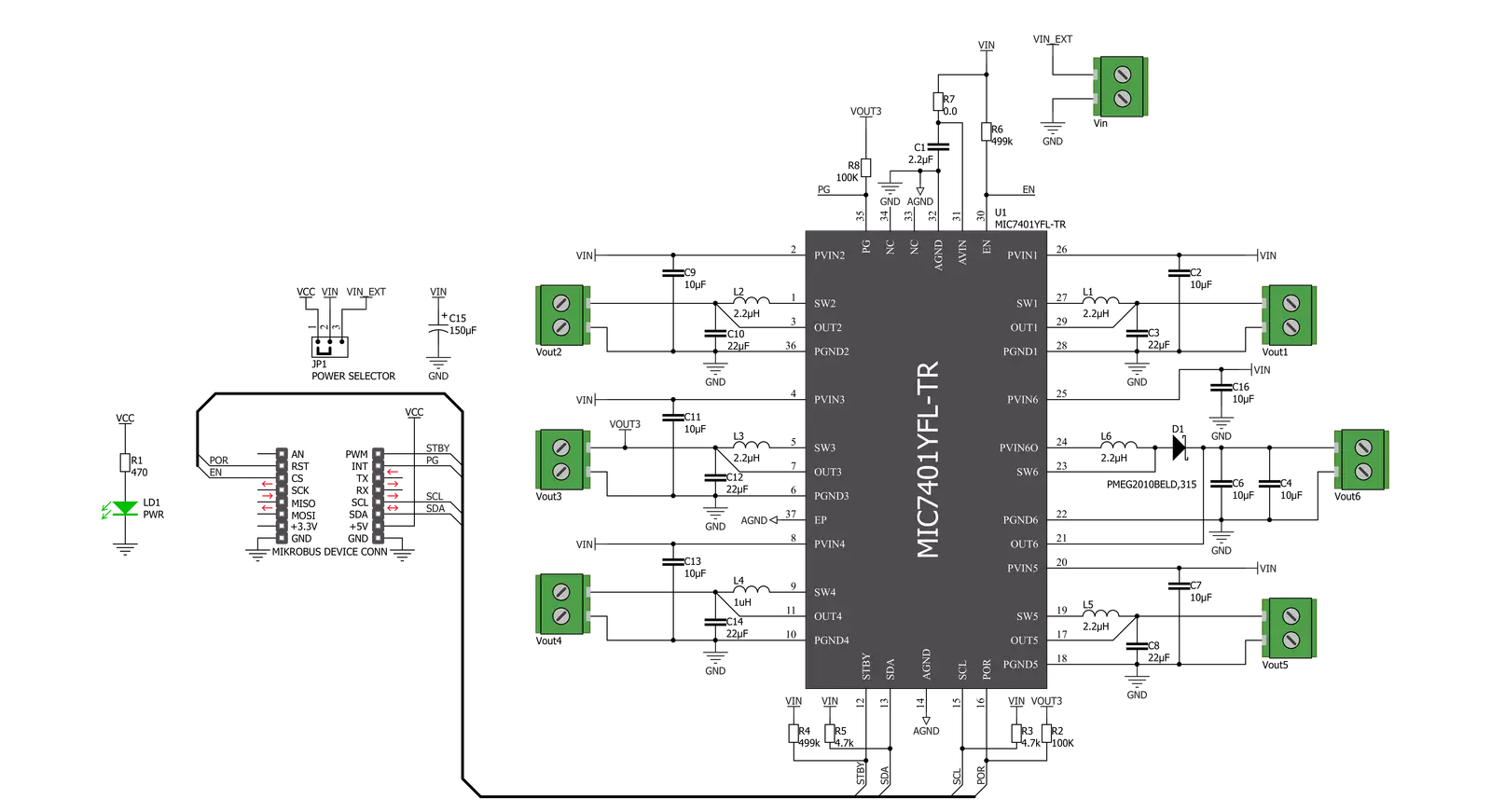
Click board™ Schematic
Step by step
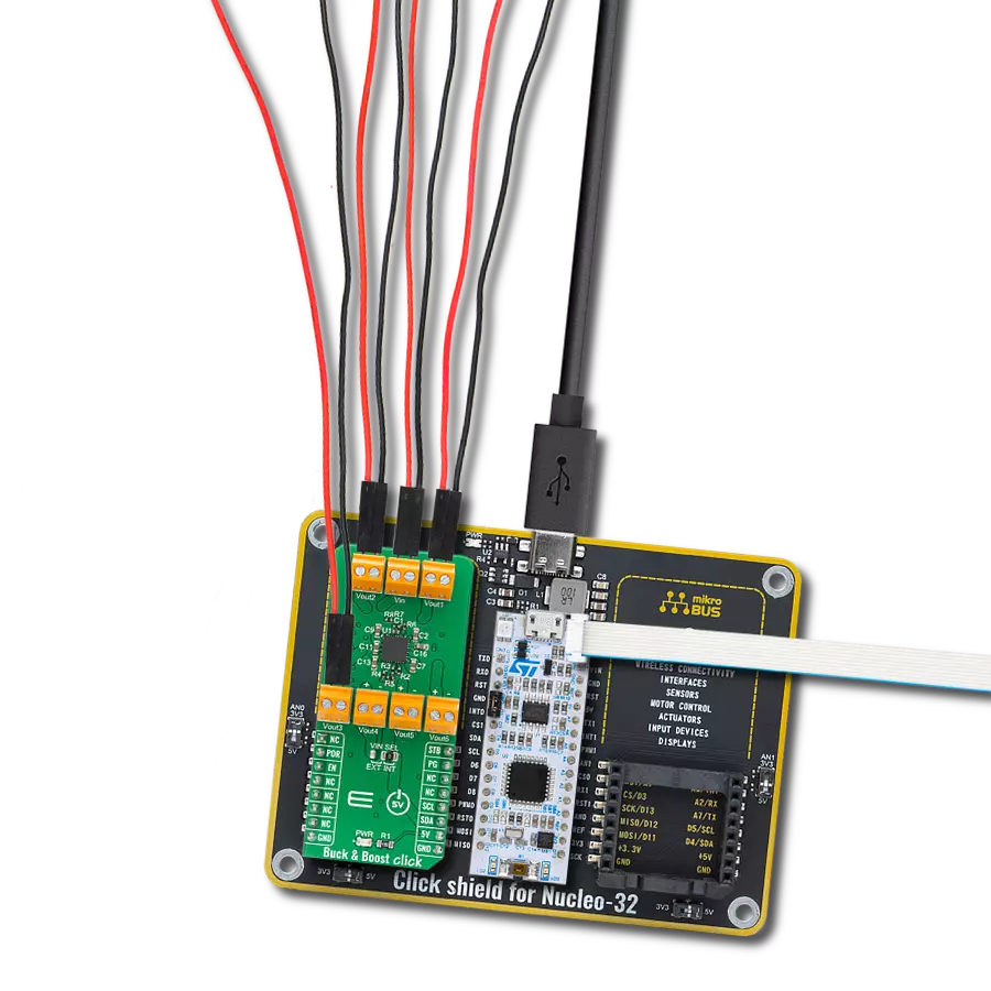
Project assembly

Start by selecting your development board and Click board™. Begin with the Nucleo 32 with STM32F031K6 MCU as your development board.


Track your results in real time
Application Output
1. Application Output - In Debug mode, the 'Application Output' window enables real-time data monitoring, offering direct insight into execution results. Ensure proper data display by configuring the environment correctly using the provided tutorial.

2. UART Terminal - Use the UART Terminal to monitor data transmission via a USB to UART converter, allowing direct communication between the Click board™ and your development system. Configure the baud rate and other serial settings according to your project's requirements to ensure proper functionality. For step-by-step setup instructions, refer to the provided tutorial.

3. Plot Output - The Plot feature offers a powerful way to visualize real-time sensor data, enabling trend analysis, debugging, and comparison of multiple data points. To set it up correctly, follow the provided tutorial, which includes a step-by-step example of using the Plot feature to display Click board™ readings. To use the Plot feature in your code, use the function: plot(*insert_graph_name*, variable_name);. This is a general format, and it is up to the user to replace 'insert_graph_name' with the actual graph name and 'variable_name' with the parameter to be displayed.

Software Support
Library Description
This library contains API for Buck & Boost Click driver.
Key functions:
bucknboost_set_buck_out_voltage- This function sets the output voltage of a desired buck channelbucknboost_set_boost_out_voltage- This function sets the output voltage of the boost channel (CH6)bucknboost_get_status- This function reads Power Good, EEPROM, and Overcurrent status registers
Open Source
Code example
The complete application code and a ready-to-use project are available through the NECTO Studio Package Manager for direct installation in the NECTO Studio. The application code can also be found on the MIKROE GitHub account.
/*!
 * @file main.c
 * @brief BucknBoost Click example
 *
 * # Description
 * This application demonstrates the use of Buck n Boost Click board.
 *
 * The demo application is composed of two sections :
 *
 * ## Application Init
 * Initializes the driver and sets the Click default configuration.
 * The default config enables the Click board and limits the current of all outputs to 1100mA.
 * It also sets the default voltages of all channels which are the following:
 * OUT1 - 1.8V, OUT2 - 1.1V, OUT3 - 1.8V, OUT4 - 1.05V, OUT5 - 1.25V, OUT6 - 12V
 *
 * ## Application Task
 * Iterates through the entire range of Buck voltages for Buck 1 output starting from the maximal output.
 * It also checks the Power Good and Overcurrent status.
 * All data is being displayed on the USB UART where you can track the program flow.
 *
 * @author Stefan Filipovic
 *
 */

#include "board.h"
#include "log.h"
#include "bucknboost.h"

static bucknboost_t bucknboost;
static log_t logger;


void application_init ( void )
{
    log_cfg_t log_cfg;  /**< Logger config object. */
    bucknboost_cfg_t bucknboost_cfg;  /**< Click config object. */

    /**
     * Logger initialization.
     * Default baud rate: 115200
     * Default log level: LOG_LEVEL_DEBUG
     * @note If USB_UART_RX and USB_UART_TX
     * are defined as HAL_PIN_NC, you will
     * need to define them manually for log to work.
     * See @b LOG_MAP_USB_UART macro definition for detailed explanation.
     */
    LOG_MAP_USB_UART( log_cfg );
    log_init( &logger, &log_cfg );
    log_info( &logger, " Application Init " );

    // Click initialization.

    bucknboost_cfg_setup( &bucknboost_cfg );
    BUCKNBOOST_MAP_MIKROBUS( bucknboost_cfg, MIKROBUS_1 );

    err_t init_flag = bucknboost_init( &bucknboost, &bucknboost_cfg );
    if ( init_flag == I2C_MASTER_ERROR )
    {
        log_error( &logger, " Application Init Error. " );
        log_info( &logger, " Please, run program again... " );

        for ( ; ; );
    }

    init_flag = bucknboost_default_cfg ( &bucknboost );
    if ( init_flag == BUCKNBOOST_ERROR )
    {
        log_error( &logger, " Default Config Error. " );
        log_info( &logger, " Please, run program again... " );

        for ( ; ; );
    }

    log_info( &logger, " Application Task " );
}

void application_task ( void )
{
    bucknboost_status_t status_data;

    for ( uint8_t cnt = BUCKNBOOST_BUCK_OUTPUT_VOLTAGE_3300mV;
          cnt <= BUCKNBOOST_BUCK_OUTPUT_VOLTAGE_800mV; cnt++ )
    {
        err_t error_check = bucknboost_set_buck_out_voltage( &bucknboost,
                                                             BUCKNBOOST_OUTPUT_CH_1,
                                                             cnt );
        if ( error_check == BUCKNBOOST_ERROR )
        {
            log_error( &logger, " Setting Buck 1 Output Voltage." );
            Delay_ms ( 1000 );
            Delay_ms ( 1000 );
            Delay_ms ( 1000 );
        }
        else
        {
            log_printf( &logger, " Buck 1 Output Voltage set to %u mV.\r\n", 3300 - cnt * 50 );

            bucknboost_get_status( &bucknboost, &status_data );
            log_printf( &logger, " Power Good status -" );
            if ( status_data.power_good == BUCKNBOOST_PGOOD_ALL_MASK )
            {
                log_printf( &logger, " Valid!\r\n" );
            }
            else
            {
                log_printf( &logger, " Not Valid! - Mask: 0x%.2X\r\n", ( uint16_t ) status_data.power_good );
            }

            log_printf( &logger, " Overcurrent status -" );
            if ( status_data.power_good == BUCKNBOOST_PGOOD_ALL_MASK )
            {
                log_printf( &logger, " No Fault!\r\n" );
            }
            else
            {
                log_printf( &logger, " Fault! - Mask: 0x%.2X\r\n", ( uint16_t ) status_data.overcurrent_fault );
            }
            log_printf( &logger, "-----------------------------------\r\n" );
        }
        Delay_ms ( 1000 );
        Delay_ms ( 1000 );
    }
}

int main ( void )
{
    /* Do not remove this line or clock might not be set correctly. */
    #ifdef PREINIT_SUPPORTED
    preinit();
    #endif

    application_init( );

    for ( ; ; )
    {
        application_task( );
    }

    return 0;
}

// ------------------------------------------------------------------------ END
Additional Support
Resources
Category:Buck-Boost