Achieve unmatched industrial CAN performance with MAX13054 and STM32F031K6
Industry-standard HS CAN

Published Oct 01, 2024
Click board™
CAN Bus Click
Dev. board
Nucleo 32 with STM32F031K6 MCU
Compiler
NECTO Studio
MCU
STM32F031K6
Fault-protected CAN-transceiver ideal for industrial network applications that require overvoltage protection
A
A
Hardware Overview
How does it work?
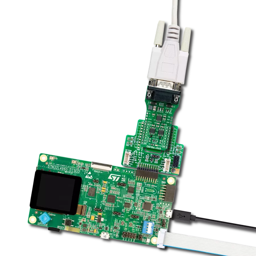
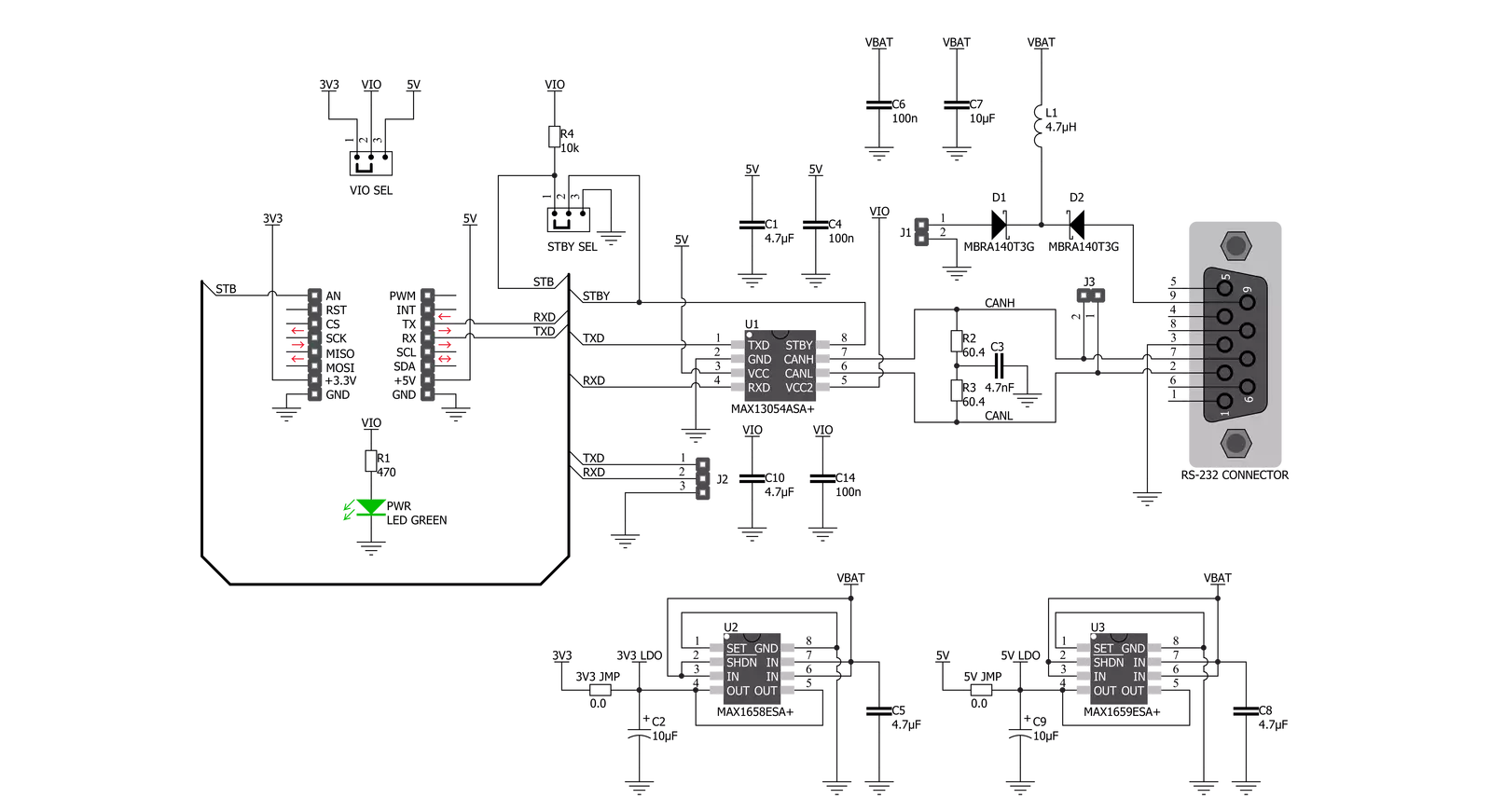
CAN Bus Click is based on the MAX13054, ±80V fault-protected CAN transceiver ideal for industrial network applications from Analog Devices. The MAX13054 links the CAN protocol controller and the physical wires of the bus lines in a control area network (CAN). These devices can be used for DeviceNet applications, requiring data rates up to 1Mbps. Its input common-mode range is greater than ±12V, exceeding the ISO11898 specification of -2V to +7V, and features ±8kV Contact Discharge protection, making these devices ideal for harsh industrial environments. Its dominant timeout feature prevents the bus from being blocked by MCU. If the TXD input is held low for greater than 1ms, the transmitter becomes disabled, driving the bus line to a recessive state. In Standby mode, when the STB pin routed on the AN and INT pin of the mikroBUS™ socket is set to a high logic state,
the transmitter is switched off, and the receiver is switched to a low-current/low-speed state. Standby mode is activated by setting the onboard SMD jumper labeled STBY SEL to an appropriate position marked as STB or GND. The MAX13054 communicates with MCU using the UART interface with the default baud rate of 115200 bps for data transfer. In addition to UART communication pins from the mikroBUS™ socket, the user can connect the TX/RX signals directly through the UART External header on the right edge of the board. This Click board™ comes equipped with the standard DB-9 connector, making interfacing with the CAN bus simple and easy. Besides, the user can connect the CAN signals directly through the CAN External header on the board's left edge. The external power supply from 2.7V to 16.5V, next to the D-9
connector, can also be brought to the header labeled BATT on the board's left side. Through SMD jumpers labeled as 3V3 JMP and 5V JMP, the MAX1658/59 from Analog Devices LDOs output voltages can power up the mikroBUS™ power rails. This feature makes the MAX13054 ideal for many applications, including automotive ones. However, it should be noted that Mikroe does not advise powering up their systems this way. That is why these jumpers are left unpopulated by default. This Click board™ can operate with either 3.3V or 5V logic voltage levels selected via the VIO SEL jumper. This way, both 3.3V and 5V capable MCUs can use the communication lines properly. Also, this Click board™ comes equipped with a library containing easy-to-use functions and an example code that can be used, as a reference, for further development.

Features overview
Development board
Nucleo 32 with STM32F031K6 MCU board provides an affordable and flexible platform for experimenting with STM32 microcontrollers in 32-pin packages. Featuring Arduino™ Nano connectivity, it allows easy expansion with specialized shields, while being mbed-enabled for seamless integration with online resources. The
board includes an on-board ST-LINK/V2-1 debugger/programmer, supporting USB reenumeration with three interfaces: Virtual Com port, mass storage, and debug port. It offers a flexible power supply through either USB VBUS or an external source. Additionally, it includes three LEDs (LD1 for USB communication, LD2 for power,
and LD3 as a user LED) and a reset push button. The STM32 Nucleo-32 board is supported by various Integrated Development Environments (IDEs) such as IAR™, Keil®, and GCC-based IDEs like AC6 SW4STM32, making it a versatile tool for developers.

Microcontroller Overview
MCU Card / MCU

Architecture
ARM Cortex-M0
MCU Memory (KB)
32
Silicon Vendor
STMicroelectronics
Pin count
32
RAM (Bytes)
4096
You complete me!
Accessories
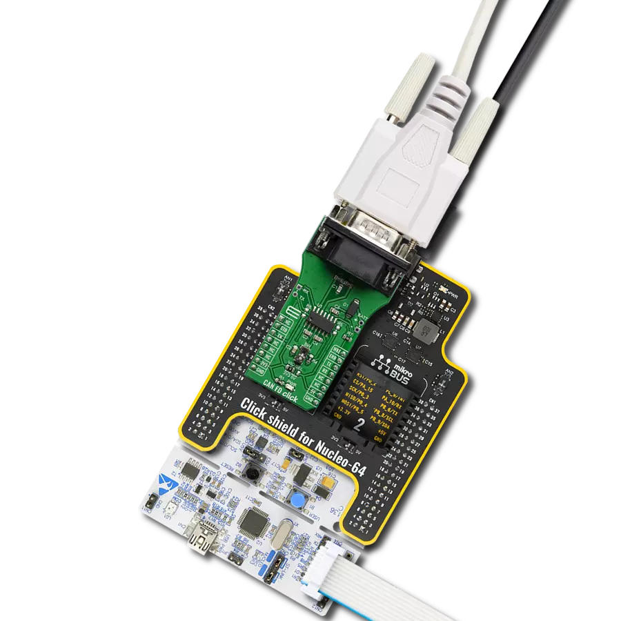
Click Shield for Nucleo-32 is the perfect way to expand your development board's functionalities with STM32 Nucleo-32 pinout. The Click Shield for Nucleo-32 provides two mikroBUS™ sockets to add any functionality from our ever-growing range of Click boards™. We are fully stocked with everything, from sensors and WiFi transceivers to motor control and audio amplifiers. The Click Shield for Nucleo-32 is compatible with the STM32 Nucleo-32 board, providing an affordable and flexible way for users to try out new ideas and quickly create prototypes with any STM32 microcontrollers, choosing from the various combinations of performance, power consumption, and features. The STM32 Nucleo-32 boards do not require any separate probe as they integrate the ST-LINK/V2-1 debugger/programmer and come with the STM32 comprehensive software HAL library and various packaged software examples. This development platform provides users with an effortless and common way to combine the STM32 Nucleo-32 footprint compatible board with their favorite Click boards™ in their upcoming projects.

DB9 Cable Female-to-Female (2m) cable is essential for establishing dependable serial data connections between devices. With its DB9 female connectors on both ends, this cable enables a seamless link between various equipment, such as computers, routers, switches, and other serial devices. Measuring 2 meters in length, it offers flexibility in arranging your setup without compromising data transmission quality. Crafted with precision, this cable ensures consistent and reliable data exchange, making it suitable for industrial applications, office environments, and home setups. Whether configuring networking equipment, accessing console ports, or utilizing serial peripherals, this cable's durable construction and robust connectors guarantee a stable connection. Simplify your data communication needs with the 2m DB9 female-to-female cable, an efficient solution designed to meet your serial connectivity requirements easily and efficiently.

Used MCU Pins
mikroBUS™ mapper
Take a closer look
Click board™ Schematic
Step by step
Project assembly

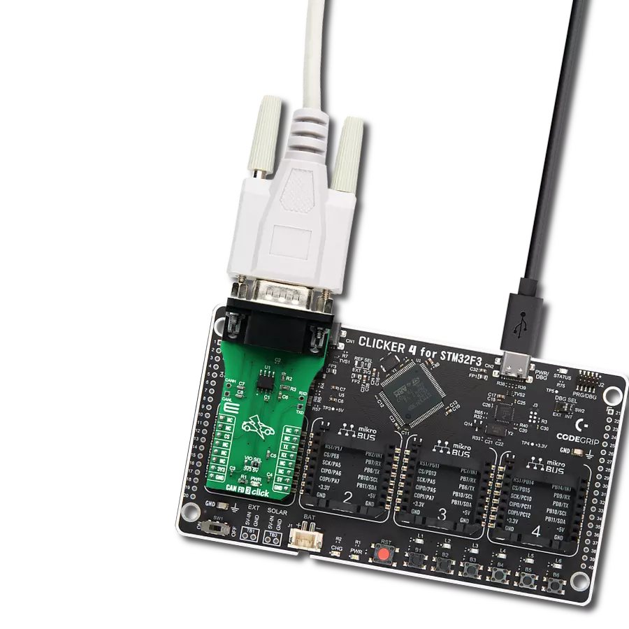
Start by selecting your development board and Click board™. Begin with the Nucleo 32 with STM32F031K6 MCU as your development board.


Track your results in real time
Application Output
1. Application Output - In Debug mode, the 'Application Output' window enables real-time data monitoring, offering direct insight into execution results. Ensure proper data display by configuring the environment correctly using the provided tutorial.

2. UART Terminal - Use the UART Terminal to monitor data transmission via a USB to UART converter, allowing direct communication between the Click board™ and your development system. Configure the baud rate and other serial settings according to your project's requirements to ensure proper functionality. For step-by-step setup instructions, refer to the provided tutorial.

3. Plot Output - The Plot feature offers a powerful way to visualize real-time sensor data, enabling trend analysis, debugging, and comparison of multiple data points. To set it up correctly, follow the provided tutorial, which includes a step-by-step example of using the Plot feature to display Click board™ readings. To use the Plot feature in your code, use the function: plot(*insert_graph_name*, variable_name);. This is a general format, and it is up to the user to replace 'insert_graph_name' with the actual graph name and 'variable_name' with the parameter to be displayed.

Software Support
Library Description
This library contains API for CAN Bus Click driver.
Key functions:
canbus_send_data- CAN Bus send data functioncanbus_set_high_speed_mode- CAN Bus high speed mode functioncanbus_set_low_current_standby_mode- CAN Bus low current standby mode function
Open Source
Code example
The complete application code and a ready-to-use project are available through the NECTO Studio Package Manager for direct installation in the NECTO Studio. The application code can also be found on the MIKROE GitHub account.
/*!
 * @file main.c
 * @brief CAN Bus Click Example.
 *
 * # Description
 * This library contains API for CAN Bus Click board™.
 * This example transmits/receives and processes data from CAN Bus Click.
 * The library initializes and defines the
 * UART bus drivers to transmit or receive data.
 *
 * The demo application is composed of two sections :
 *
 * ## Application Init
 * Initializes driver, wake-up module, and set high-speed operation mode.
 *
 * ## Application Task
 * Transmitter/Receiver task depends on uncommented code.
 * Receiver logging each received byte to the UART for data logging,
 * while transmitted send messages every 2 seconds.
 *
 * ## Additional Function
 * - static void canbus_clear_app_buf ( void ) - Function clears memory of app_buf.
 * - static err_t canbus_process ( void ) - The general process of collecting presponce
 *   that a module sends.
 *
 * @author Nenad Filipovic
 *
 */

#include "board.h"
#include "log.h"
#include "canbus.h"

#define PROCESS_BUFFER_SIZE 200

// #define TRANSMIT
#define RECIEVER

static canbus_t canbus;
static log_t logger;

static char app_buf[ PROCESS_BUFFER_SIZE ] = { 0 };
static int32_t app_buf_len = 0;
static int32_t app_buf_cnt = 0;
unsigned char demo_message[ 9 ] = { 'M', 'i', 'k', 'r', 'o', 'E', 13, 10, 0 };

/**
 * @brief CAN Bus clearing application buffer.
 * @details This function clears memory of application buffer and reset it's length and counter.
 * @note None.
 */
static void canbus_clear_app_buf ( void );

/**
 * @brief CAN Bus data reading function.
 * @details This function reads data from device and concatenates data to application buffer.
 *
 * @return @li @c  0 - Read some data.
 *         @li @c -1 - Nothing is read.
 *         @li @c -2 - Application buffer overflow.
 *
 * See #err_t definition for detailed explanation.
 * @note None.
 */
static err_t canbus_process ( void );

void application_init ( void ) {
    log_cfg_t log_cfg;        /**< Logger config object. */
    canbus_cfg_t canbus_cfg;  /**< Click config object. */

    /**
     * Logger initialization.
     * Default baud rate: 115200
     * Default log level: LOG_LEVEL_DEBUG
     * @note If USB_UART_RX and USB_UART_TX
     * are defined as HAL_PIN_NC, you will
     * need to define them manually for log to work.
     * See @b LOG_MAP_USB_UART macro definition for detailed explanation.
     */
    LOG_MAP_USB_UART( log_cfg );
    log_init( &logger, &log_cfg );
    log_info( &logger, " Application Init " );

    // Click initialization.

    canbus_cfg_setup( &canbus_cfg );
    CANBUS_MAP_MIKROBUS( canbus_cfg, MIKROBUS_1 );
    err_t init_flag  = canbus_init( &canbus, &canbus_cfg );
    if ( init_flag == UART_ERROR ) {
        log_error( &logger, " Application Init Error. " );
        log_info( &logger, " Please, run program again... " );

        for ( ; ; );
    }

    canbus_default_cfg ( &canbus );
    app_buf_len = 0;
    app_buf_cnt = 0;
    log_info( &logger, " Application Task " );
    Delay_ms ( 100 );

    canbus_set_high_speed_mode( &canbus );
    Delay_ms ( 100 );

    #ifdef TRANSMIT

        log_printf( &logger, "    Send data:    \r\n" );
        log_printf( &logger, "      MikroE      \r\n" );
        log_printf( &logger, "------------------\r\n" );
        log_printf( &logger, "  Transmit data   \r\n" );
        Delay_ms ( 1000 );

    #endif

    #ifdef RECIEVER

        log_printf( &logger, "   Receive data  \r\n" );
        Delay_ms ( 1000 );
        Delay_ms ( 1000 );

    #endif

    log_printf( &logger, "------------------\r\n" );
}

void application_task ( void ) {
   #ifdef TRANSMIT

        canbus_send_data( &canbus, demo_message );
        log_printf( &logger, "\t%s", demo_message );
        Delay_ms ( 1000 );
        Delay_ms ( 1000 );
        log_printf( &logger, "------------------\r\n" );

    #endif

    #ifdef RECIEVER

        canbus_process( );

        if ( app_buf_len > 0 ) {
            log_printf( &logger, "%s", app_buf );
            canbus_clear_app_buf(  );
        }

    #endif
}

int main ( void )
{
    /* Do not remove this line or clock might not be set correctly. */
    #ifdef PREINIT_SUPPORTED
    preinit();
    #endif

    application_init( );

    for ( ; ; )
    {
        application_task( );
    }

    return 0;
}

static void canbus_clear_app_buf ( void ) {
    memset( app_buf, 0, app_buf_len );
    app_buf_len = 0;
    app_buf_cnt = 0;
}

static err_t canbus_process ( void ) {
    int32_t rx_size;
    char rx_buff[ PROCESS_BUFFER_SIZE ] = { 0 };

    rx_size = canbus_generic_read( &canbus, rx_buff, PROCESS_BUFFER_SIZE );

    if ( rx_size > 0 ) {
        int32_t buf_cnt = 0;

        if ( app_buf_len + rx_size >= PROCESS_BUFFER_SIZE ) {
            canbus_clear_app_buf( );
            return CANBUS_ERROR;
        } else {
            buf_cnt = app_buf_len;
            app_buf_len += rx_size;
        }

        for ( int32_t rx_cnt = 0; rx_cnt < rx_size; rx_cnt++ ) {
            if ( rx_buff[ rx_cnt ] != 0 ) {
                app_buf[ ( buf_cnt + rx_cnt ) ] = rx_buff[ rx_cnt ];
            } else {
                app_buf_len--;
                buf_cnt--;
            }

        }
        return CANBUS_OK;
    }
    return CANBUS_ERROR;
}

// ------------------------------------------------------------------------ END