Achieve high-performance DC motor control with DRV8245P and STM32F031K6
Single full-bridge or independent half-bridge driver

Published Oct 01, 2024
Click board™
DC Motor 29 Click
Dev. board
Nucleo 32 with STM32F031K6 MCU
Compiler
NECTO Studio
MCU
STM32F031K6
Simplify the process of controlling DC motors in various automotive applications, ensuring they work smoothly and reliably for multiple functions
A
A
Hardware Overview
How does it work?
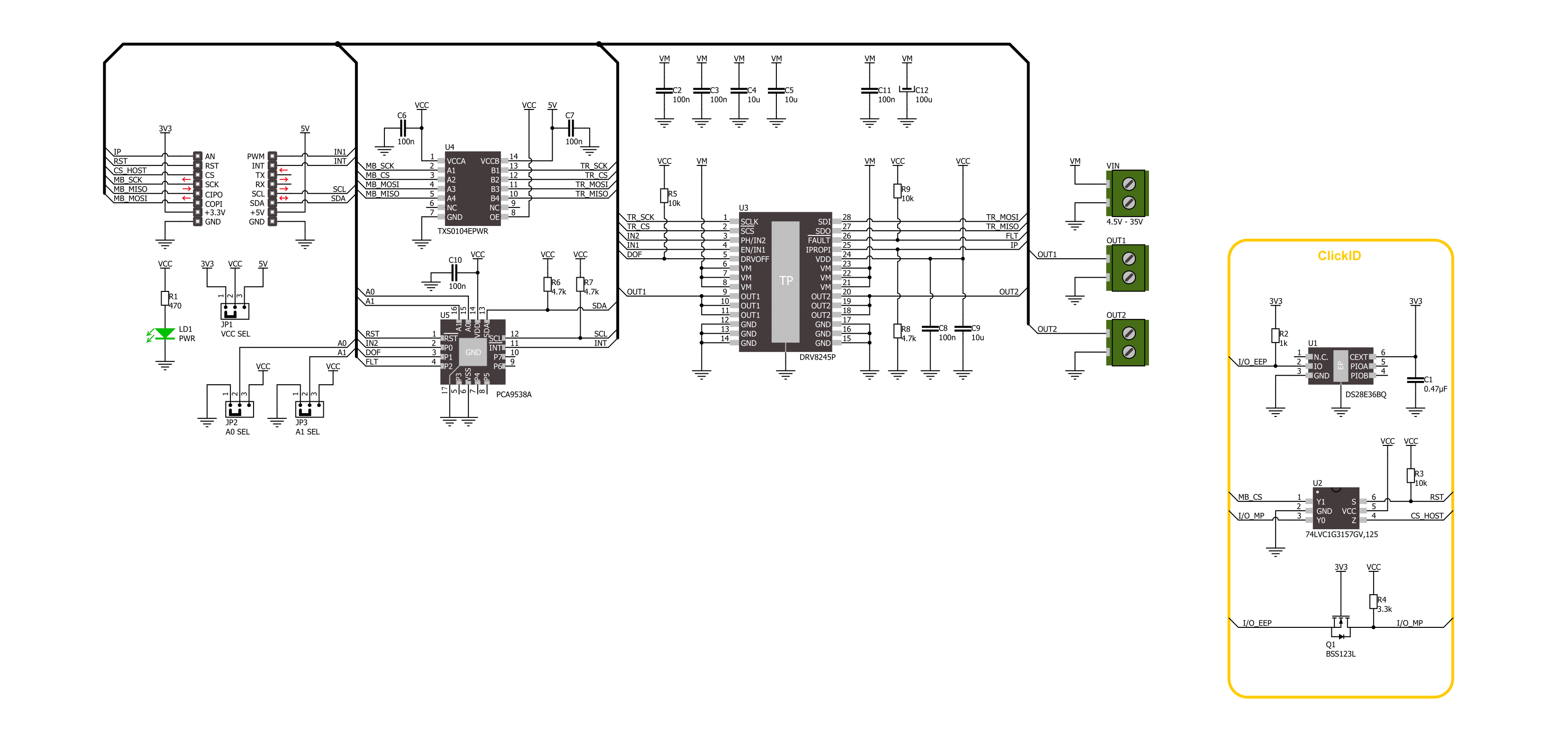
DC Motor 29 Click is based on the DRV8245P, an automotive H-Bridge driver with integrated current sense and diagnostic from Texas Instruments. The driver operates from 4.5V up to 35V and supports a wide range of output load currents for various motors and loads. It integrates an N-channel H-bridge, charge pump regulator, high-side current sensing with regulation, current proportional output, and protection circuitry. The H-bridge output power stage can be operated in different control modes, which allows you to drive a single bidirectional brushed DC motor or two unidirectional brushed DC motors over screw terminals. The driver offers voltage monitoring, load diagnostics, and protection features against overcurrent and overtemperature.
DC Motor 29 Click uses a standard 4-wire SPI serial interface to communicate with the host MCU. The TXS0104, a 4-bit bidirectional voltage-level translator from Texas Instruments, does the logic-level translation. The driver load current analog feedback is available over the IP pin. The controller input 1 for bridge operation is available over the IN1 pin. The PCA9538, an 8-bit I/O port from NXP, provides additional functionalities from the motor driver to the host MCU and can be reset over the RST pin. It provides an input of the controller input 2 for bridge operation. These two controller inputs allow you to use different control schemes. The mode scheme can be changed anytime over the software. The I/O port also allows you to disable
the motor driver. The fault conditions are also monitored over this IC. If a fault condition occurs, the host MCU will be asserted over the FLT pin. The I2C address of the I/O port can be selected over the ADDR SEL jumpers. This Click board™ can operate with either 3.3V or 5V logic voltage levels selected via the VCC SEL jumper. This way, both 3.3V and 5V capable MCUs can use the communication lines properly. Also, this Click board™ comes equipped with a library containing easy-to-use functions and an example code that can be used as a reference for further development.

Features overview
Development board
Nucleo 32 with STM32F031K6 MCU board provides an affordable and flexible platform for experimenting with STM32 microcontrollers in 32-pin packages. Featuring Arduino™ Nano connectivity, it allows easy expansion with specialized shields, while being mbed-enabled for seamless integration with online resources. The
board includes an on-board ST-LINK/V2-1 debugger/programmer, supporting USB reenumeration with three interfaces: Virtual Com port, mass storage, and debug port. It offers a flexible power supply through either USB VBUS or an external source. Additionally, it includes three LEDs (LD1 for USB communication, LD2 for power,
and LD3 as a user LED) and a reset push button. The STM32 Nucleo-32 board is supported by various Integrated Development Environments (IDEs) such as IAR™, Keil®, and GCC-based IDEs like AC6 SW4STM32, making it a versatile tool for developers.

Microcontroller Overview
MCU Card / MCU

Architecture
ARM Cortex-M0
MCU Memory (KB)
32
Silicon Vendor
STMicroelectronics
Pin count
32
RAM (Bytes)
4096
You complete me!
Accessories
Click Shield for Nucleo-32 is the perfect way to expand your development board's functionalities with STM32 Nucleo-32 pinout. The Click Shield for Nucleo-32 provides two mikroBUS™ sockets to add any functionality from our ever-growing range of Click boards™. We are fully stocked with everything, from sensors and WiFi transceivers to motor control and audio amplifiers. The Click Shield for Nucleo-32 is compatible with the STM32 Nucleo-32 board, providing an affordable and flexible way for users to try out new ideas and quickly create prototypes with any STM32 microcontrollers, choosing from the various combinations of performance, power consumption, and features. The STM32 Nucleo-32 boards do not require any separate probe as they integrate the ST-LINK/V2-1 debugger/programmer and come with the STM32 comprehensive software HAL library and various packaged software examples. This development platform provides users with an effortless and common way to combine the STM32 Nucleo-32 footprint compatible board with their favorite Click boards™ in their upcoming projects.

DC Gear Motor - 430RPM (3-6V) represents an all-in-one combination of a motor and gearbox, where the addition of gear leads to a reduction of motor speed while increasing the torque output. This gear motor has a spur gearbox, making it a highly reliable solution for applications with lower torque and speed requirements. The most critical parameters for gear motors are speed, torque, and efficiency, which are, in this case, 520RPM with no load and 430RPM at maximum efficiency, alongside a current of 60mA and a torque of 50g.cm. Rated for a 3-6V operational voltage range and clockwise/counterclockwise rotation direction, this motor represents an excellent solution for many functions initially performed by brushed DC motors in robotics, medical equipment, electric door locks, and much more.

Used MCU Pins
mikroBUS™ mapper
Take a closer look
Click board™ Schematic
Step by step
Project assembly

Start by selecting your development board and Click board™. Begin with the Nucleo 32 with STM32F031K6 MCU as your development board.


Track your results in real time
Application Output
1. Application Output - In Debug mode, the 'Application Output' window enables real-time data monitoring, offering direct insight into execution results. Ensure proper data display by configuring the environment correctly using the provided tutorial.

2. UART Terminal - Use the UART Terminal to monitor data transmission via a USB to UART converter, allowing direct communication between the Click board™ and your development system. Configure the baud rate and other serial settings according to your project's requirements to ensure proper functionality. For step-by-step setup instructions, refer to the provided tutorial.

3. Plot Output - The Plot feature offers a powerful way to visualize real-time sensor data, enabling trend analysis, debugging, and comparison of multiple data points. To set it up correctly, follow the provided tutorial, which includes a step-by-step example of using the Plot feature to display Click board™ readings. To use the Plot feature in your code, use the function: plot(*insert_graph_name*, variable_name);. This is a general format, and it is up to the user to replace 'insert_graph_name' with the actual graph name and 'variable_name' with the parameter to be displayed.

Software Support
Library Description
This library contains API for DC Motor 29 Click driver.
Key functions:
dcmotor29_register_write- DC Motor 29 data register writing function.dcmotor29_port_expander_read- DC Motor 29 port ecpander read register function.dcmotor29_drive_motor- DC Motor 29 drive motor function.
Open Source
Code example
The complete application code and a ready-to-use project are available through the NECTO Studio Package Manager for direct installation in the NECTO Studio. The application code can also be found on the MIKROE GitHub account.
/*!
 * @file main.c
 * @brief DC Motor 29 Click example
 *
 * # Description
 * This example demonstrates the use of the DC Motor 29 Click board by driving the
 * motor in both directions with braking and coasting in between.
 *
 * The demo application is composed of two sections :
 *
 * ## Application Init
 * Initializes the driver and performs the Click default configuration.
 *
 * ## Application Task
 * Drives the motor in both directions with coasting and braking in between, every sate is lasting 5 seconds.
 *
 * @author Stefan Ilic
 *
 */

#include "board.h"
#include "log.h"
#include "dcmotor29.h"

static dcmotor29_t dcmotor29;
static log_t logger;

void application_init ( void )
{
    log_cfg_t log_cfg;  /**< Logger config object. */
    dcmotor29_cfg_t dcmotor29_cfg;  /**< Click config object. */

    /**
     * Logger initialization.
     * Default baud rate: 115200
     * Default log level: LOG_LEVEL_DEBUG
     * @note If USB_UART_RX and USB_UART_TX
     * are defined as HAL_PIN_NC, you will
     * need to define them manually for log to work.
     * See @b LOG_MAP_USB_UART macro definition for detailed explanation.
     */
    LOG_MAP_USB_UART( log_cfg );
    log_init( &logger, &log_cfg );
    log_info( &logger, " Application Init " );

    // Click initialization.
    dcmotor29_cfg_setup( &dcmotor29_cfg );
    DCMOTOR29_MAP_MIKROBUS( dcmotor29_cfg, MIKROBUS_1 );
    if ( SPI_MASTER_ERROR == dcmotor29_init( &dcmotor29, &dcmotor29_cfg ) )
    {
        log_error( &logger, " Communication init." );
        for ( ; ; );
    }

    if ( DCMOTOR29_ERROR == dcmotor29_default_cfg ( &dcmotor29 ) )
    {
        log_error( &logger, " Default configuration." );
        for ( ; ; );
    }

    log_info( &logger, " Application Task " );
}

void application_task ( void )
{
    dcmotor29_drive_motor( &dcmotor29, DCMOTOR29_DRIVE_MOTOR_CW );
    log_printf( &logger, " Driving motor Clockwise \r\n" );
    Delay_ms ( 1000 );
    Delay_ms ( 1000 );
    Delay_ms ( 1000 );
    Delay_ms ( 1000 );
    Delay_ms ( 1000 );

    dcmotor29_drive_motor( &dcmotor29, DCMOTOR29_DRIVE_MOTOR_BRAKE );
    log_printf( &logger, " Brake is on \r\n" );
    Delay_ms ( 1000 );
    Delay_ms ( 1000 );
    Delay_ms ( 1000 );
    Delay_ms ( 1000 );
    Delay_ms ( 1000 );

    dcmotor29_drive_motor( &dcmotor29, DCMOTOR29_DRIVE_MOTOR_CCW );
    log_printf( &logger, " Driving motor counter-clockwise \r\n" );
    Delay_ms ( 1000 );
    Delay_ms ( 1000 );
    Delay_ms ( 1000 );
    Delay_ms ( 1000 );
    Delay_ms ( 1000 );

    dcmotor29_drive_motor( &dcmotor29, DCMOTOR29_DRIVE_MOTOR_COASTING );
    log_printf( &logger, " Driving motor Coasting \r\n" );
    Delay_ms ( 1000 );
    Delay_ms ( 1000 );
    Delay_ms ( 1000 );
    Delay_ms ( 1000 );
    Delay_ms ( 1000 );
}

int main ( void )
{
    /* Do not remove this line or clock might not be set correctly. */
    #ifdef PREINIT_SUPPORTED
    preinit();
    #endif

    application_init( );

    for ( ; ; )
    {
        application_task( );
    }

    return 0;
}

// ------------------------------------------------------------------------ END


