Redefine audio quality and deliver the best sonic experience by combining V1000 and STM32F031K6
Revolutionizing your sound: Unleash the power of ultimate audio with our multi-effects DSP!

Published Oct 01, 2024
Click board™
DSP Click
Dev. board
Nucleo 32 with STM32F031K6 MCU
Compiler
NECTO Studio
MCU
STM32F031K6
Dive into the future of audio with our multi-effects DSP, providing an unmatched audio journey that exceeds all expectations
A
A
Hardware Overview
How does it work?
DSP Click is based on the V1000, a complete multi-effects audio DSP with ultra-high quality audio performance in a rapid ‘time-to-market’ solution from Coolaudio. The V1000 is a specialized microprocessor chip with its architecture optimized for the needs of digital signal processing. It includes serially programmable SRAM for program development and integrated RAM with 16 built-in effects such as multiple reverbs, echo, phaser, chorus, flanger, and more. Alongside the 16 internal programs, programmable SRAM is easily accessible through the I2C serial interface by setting the V1000 to external mode, while in internal mode, the four GPIO pins (P0-P3) may be used to select the different algorithms. Combined with a low-cost codec like the V4220 from Coolaudio, this Click board™ provides an ultra-low-cost FX solution. The V4220 is a high-performance 24-bit audio codec providing stereo A/D and D/A converters using the
latest conversion technology. It operates from a single +5V power supply, features low power consumption, and a selectable de-emphasis filter for 32, 44.1, and 48kHz sample rates. It also includes an analog volume control architecture that can make a 113.5dB attenuation in 0.5dB steps, preserving dynamic range during attenuation. The V4220 provides a serial interface to read/write the internal registers operating in either Master or Slave Mode. This audio player consists of two analog channels, input and output routed to the 3.5mm audio jack connectors. The functional configuration of these audio channels consists of two dual audio operational amplifiers, the RC4580 from Texas Instruments, used as headphone amplifiers. It offers low noise, high gain-bandwidth, low harmonic distortion, and high output current, powered by ±15V obtained by the TPS65131, dual-output DC-DC converter generating a positive output voltage up to 15V and
a negative output voltage down to –15V with output currents in a 200mA range from Texas Instruments. Also, this Click board™ can be reset through the Hardware Reset pin, labeled as RST on the mikroBUS™ socket, and has two jumpers on its bottom side labeled as JP1 and JP2, which very easily adjusts the way the V1000 communicates with the MCU, between I2C communication or IO pins, by positioning SMD jumpers to an appropriate position. Note that all jumpers must be placed on the same side, or the Click board™ may become unresponsive. This Click board™ can be operated only with a 5V logic voltage level. The board must perform appropriate logic voltage level conversion before using MCUs with different logic levels. Also, it comes equipped with a library containing functions and an example code that can be used as a reference for further development.


Features overview
Development board
Nucleo 32 with STM32F031K6 MCU board provides an affordable and flexible platform for experimenting with STM32 microcontrollers in 32-pin packages. Featuring Arduino™ Nano connectivity, it allows easy expansion with specialized shields, while being mbed-enabled for seamless integration with online resources. The
board includes an on-board ST-LINK/V2-1 debugger/programmer, supporting USB reenumeration with three interfaces: Virtual Com port, mass storage, and debug port. It offers a flexible power supply through either USB VBUS or an external source. Additionally, it includes three LEDs (LD1 for USB communication, LD2 for power,
and LD3 as a user LED) and a reset push button. The STM32 Nucleo-32 board is supported by various Integrated Development Environments (IDEs) such as IAR™, Keil®, and GCC-based IDEs like AC6 SW4STM32, making it a versatile tool for developers.

Microcontroller Overview
MCU Card / MCU

Architecture
ARM Cortex-M0
MCU Memory (KB)
32
Silicon Vendor
STMicroelectronics
Pin count
32
RAM (Bytes)
4096
You complete me!
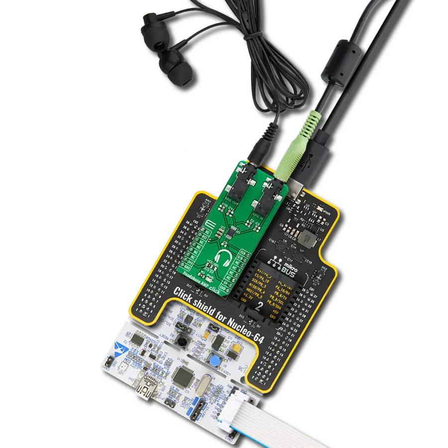
Accessories
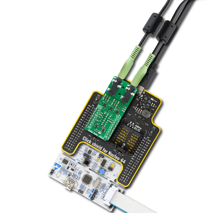
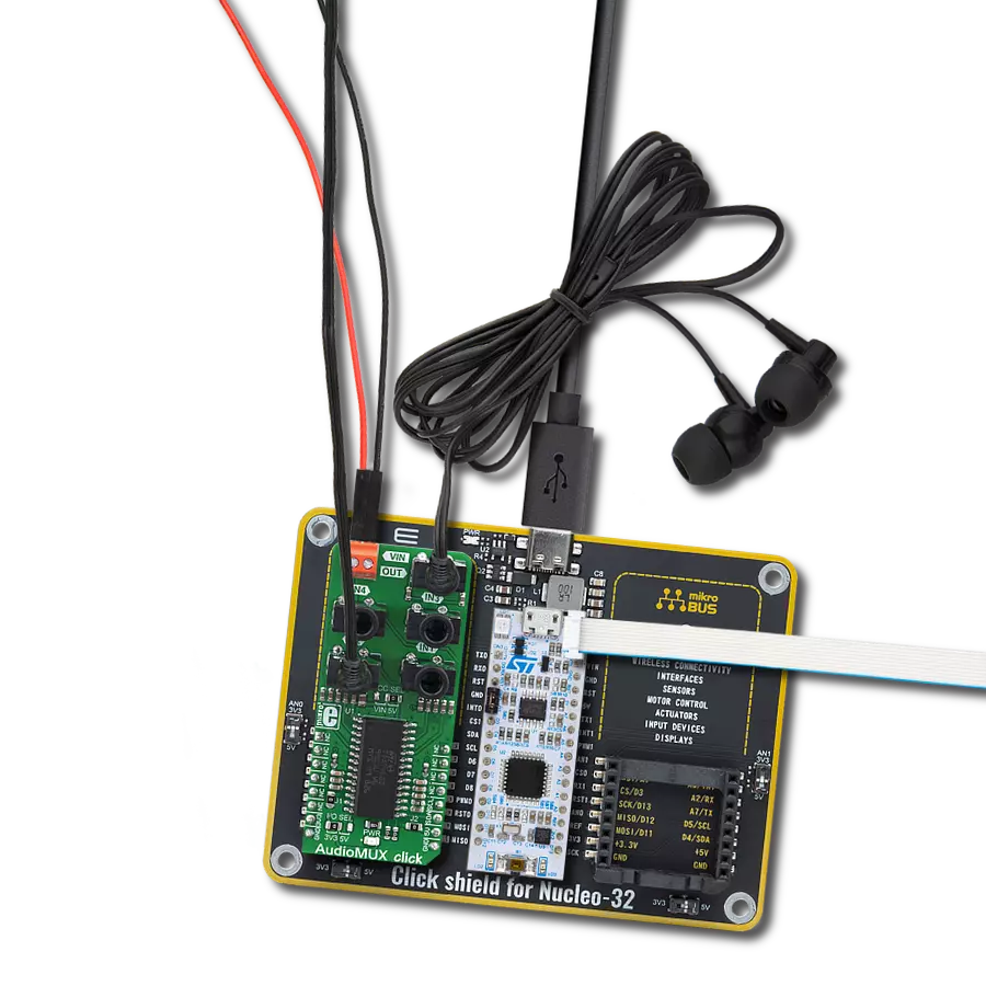
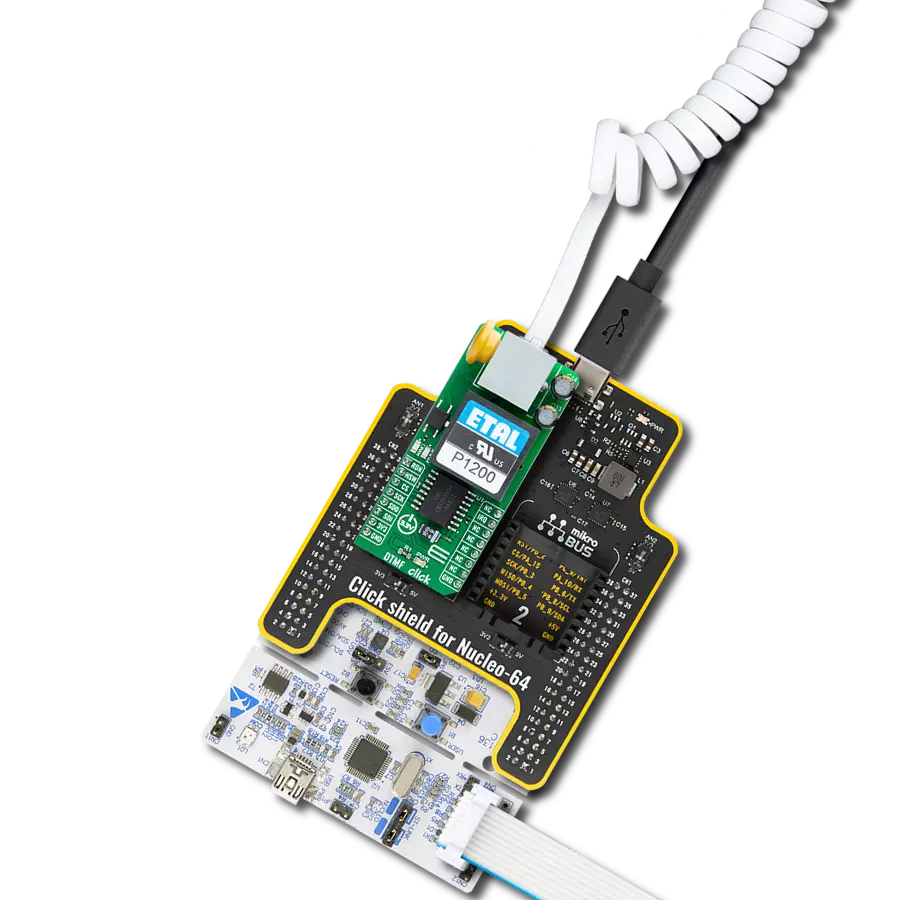
Click Shield for Nucleo-32 is the perfect way to expand your development board's functionalities with STM32 Nucleo-32 pinout. The Click Shield for Nucleo-32 provides two mikroBUS™ sockets to add any functionality from our ever-growing range of Click boards™. We are fully stocked with everything, from sensors and WiFi transceivers to motor control and audio amplifiers. The Click Shield for Nucleo-32 is compatible with the STM32 Nucleo-32 board, providing an affordable and flexible way for users to try out new ideas and quickly create prototypes with any STM32 microcontrollers, choosing from the various combinations of performance, power consumption, and features. The STM32 Nucleo-32 boards do not require any separate probe as they integrate the ST-LINK/V2-1 debugger/programmer and come with the STM32 comprehensive software HAL library and various packaged software examples. This development platform provides users with an effortless and common way to combine the STM32 Nucleo-32 footprint compatible board with their favorite Click boards™ in their upcoming projects.

Used MCU Pins
mikroBUS™ mapper
Take a closer look
Click board™ Schematic

Step by step
Project assembly

Start by selecting your development board and Click board™. Begin with the Nucleo 32 with STM32F031K6 MCU as your development board.


Software Support
Library Description
This library contains API for DSP Click driver.
Key functions:
dsp_set_effect- DSP reverb and multi-effects setting functiondsp_power_on- DSP power on the device functiondsp_reset- DSP reset the device function
Open Source
Code example
The complete application code and a ready-to-use project are available through the NECTO Studio Package Manager for direct installation in the NECTO Studio. The application code can also be found on the MIKROE GitHub account.
/*!
 * @file main.c
 * @brief DSP Click Example.
 *
 * # Description
 * This application controls reverb and multi-effects Digital Multi-Effects DSP
 * provides different sound performance of the DSP Click.
 *
 * The demo application is composed of two sections :
 *
 * ## Application Init
 * Initializes GPIO driver, set the default configuration and start to write log.
 *
 * ## Application Task
 * This is an example that shows the use of a DSP Click board.
 * In this example, we change different sound effects
 * such as multiple reverbs, echo, phaser, chorus, flanger, etc. every 10 sec.
 * Results are being sent to the Usart Terminal where you can track their changes.
 *
 * @author Nenad Filipovic
 *
 */

#include "board.h"
#include "log.h"
#include "dsp.h"

static dsp_t dsp;       /**< DSP Click driver object. */
static log_t logger;    /**< Logger object. */
static uint8_t effects = DSP_SET_EFFECT_MEDIUM;


void display_effects ( void ) {
    switch ( effects ) {
        case DSP_SET_EFFECT_MEDIUM: {
            log_printf( &logger, " Reverb, Small hall (1.5 sec.)\r\n" );
            break;
        }
        case DSP_SET_EFFECT_CHAMBR7B: {
            log_printf( &logger, " Reverb, Big hall (2.8 sec.)\r\n" );
            break;
        }
        case DSP_SET_EFFECT_ROOM3B: {
            log_printf( &logger, " Reverb, Room (1.8 sec.)\r\n" );
            break;
        }
        case DSP_SET_EFFECT_CHAMBER2: {
            log_printf( &logger, " Reverb, Church (7 sec.)\r\n" );
            break;
        }
        case DSP_SET_EFFECT_REVERS3B: {
            log_printf( &logger, " Reverb Reverse (1.2 sec.)\r\n" );
            break;
        }
        case DSP_SET_EFFECT_GATED4B: {
            log_printf( &logger, " Reverb Gated (0.8 sec.)\r\n" );
            break;
        }
        case DSP_SET_EFFECT_ROOM2A: {
            log_printf( &logger, " Reverb Chapel (3 sec.)\r\n" );
            break;
        }
        case DSP_SET_EFFECT_SPRING3B: {
            log_printf( &logger, " Reverb Spring (2 sec.)\r\n" );
            break;
        }
        case DSP_SET_EFFECT_PHASER1: {
            log_printf( &logger, " Phaser\r\n" );
            break;
        }
        case DSP_SET_EFFECT_FLANGER2: {
            log_printf( &logger, " Flanger\r\n" );
            break;
        }
        case DSP_SET_EFFECT_DELAY7: {
            log_printf( &logger, " Echo\r\n" );
            break;
        }
        case DSP_SET_EFFECT_CHORUS4: {
            log_printf( &logger, " Chorus\r\n" );
            break;
        }
        case DSP_SET_EFFECT_EARLREF4: {
            log_printf( &logger, " Early Reflection\r\n" );
            break;
        }
        case DSP_SET_EFFECT_AMB4: {
            log_printf( &logger, " Big Ambience\r\n" );
            break;
        }
        case DSP_SET_EFFECT_DELAY3: {
            log_printf( &logger, " Stereo Delay\r\n" );
            break;
        }
        case DSP_SET_EFFECT_DELAY1: {
            log_printf( &logger, " Slap-back Delay\r\n" );
            break;
        }
        default: {
            log_error( &logger, " Error" );
            break;
        }
    }
}

void application_init ( void ) {
    log_cfg_t log_cfg;  /**< Logger config object. */
    dsp_cfg_t dsp_cfg;  /**< Click config object. */

    /**
     * Logger initialization.
     * Default baud rate: 115200
     * Default log level: LOG_LEVEL_DEBUG
     * @note If USB_UART_RX and USB_UART_TX
     * are defined as HAL_PIN_NC, you will
     * need to define them manually for log to work.
     * See @b LOG_MAP_USB_UART macro definition for detailed explanation.
     */
    LOG_MAP_USB_UART( log_cfg );
    log_init( &logger, &log_cfg );
    log_printf( &logger, "\r\n" );
    log_info( &logger, " Application Init " );

    // Click initialization.

    dsp_cfg_setup( &dsp_cfg );
    DSP_MAP_MIKROBUS( dsp_cfg, MIKROBUS_1 );
    if ( dsp_init( &dsp, &dsp_cfg ) == DIGITAL_OUT_UNSUPPORTED_PIN ) {
        log_error( &logger, " Application Init Error. " );
        log_info( &logger, " Please, run program again... " );

        for ( ; ; );
    }
    dsp_default_cfg ( &dsp );
    log_info( &logger, " Application Task \r\n" );
    Delay_ms ( 100 );

    log_printf( &logger, "-------------------------------\r\n" );
    log_printf( &logger, "           DSP Click           \r\n" );
    log_printf( &logger, "-------------------------------\r\n" );
    log_printf( &logger, "     Digital Multi-Effects     \r\n" );
}

void application_task ( void ) {
    log_printf( &logger, "-------------------------------\r\n" );
    dsp_set_effect( &dsp, effects );
    display_effects( );

    effects++;
    if ( effects > DSP_SET_EFFECT_DELAY1 ) {
        effects = DSP_SET_EFFECT_MEDIUM;
    }

    // 10 seconds delay
    Delay_ms ( 1000 );
    Delay_ms ( 1000 );
    Delay_ms ( 1000 );
    Delay_ms ( 1000 );
    Delay_ms ( 1000 );
    Delay_ms ( 1000 );
    Delay_ms ( 1000 );
    Delay_ms ( 1000 );
    Delay_ms ( 1000 );
    Delay_ms ( 1000 );
}

int main ( void )
{
    /* Do not remove this line or clock might not be set correctly. */
    #ifdef PREINIT_SUPPORTED
    preinit();
    #endif

    application_init( );

    for ( ; ; )
    {
        application_task( );
    }

    return 0;
}

// ------------------------------------------------------------------------ END
Additional Support
Resources
Category:Signal Processing