Provide a secure and energy-efficient environment for your applications with TCM515 and STM32F031K6
Freedom to communicate, anywhere, anytime!
Published Oct 01, 2024
Click board™
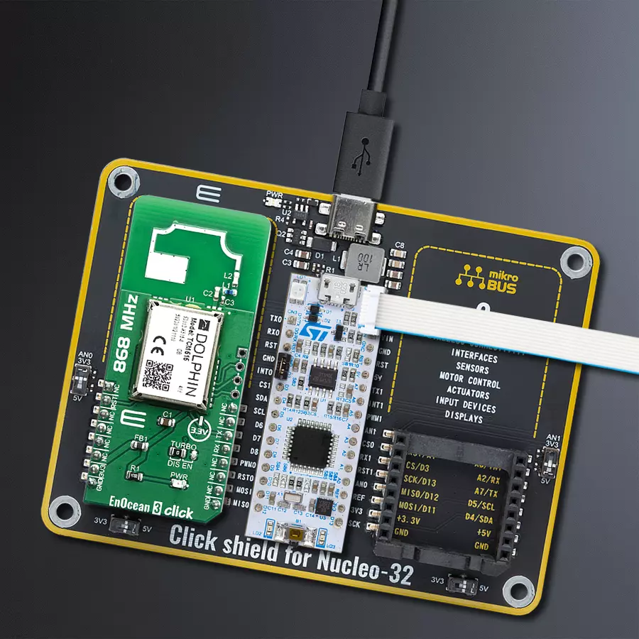
EnOcean 3 Click
Dev. board
Nucleo 32 with STM32F031K6 MCU
Compiler
NECTO Studio
MCU
STM32F031K6
Our ultra-low power transceiver gateway module is designed to seamlessly integrate EnOcean communication into your IoT ecosystem, enhancing connectivity and energy efficiency.
A
A
Hardware Overview
How does it work?
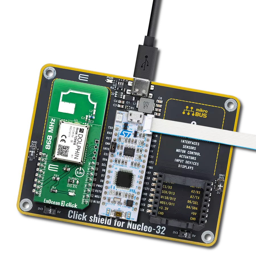
EnOcean 3 Click is based on the TCM515, a transceiver gateway module that operates at 868MHz radio band module from EnOcean. Its fully integrated radio capability enables communications with other devices by using onboard PCB antenna, so no additional antennas are needed for testing this device. The TCM 515 can work in three functional modes: Telegram Reception, Telegram Transmission, Low Power Sleep. In receive mode, TCM 515 processes received radio telegrams and verify correct frame structure and checksum. In transmit mode, TCM 515 receives radio-telegrams for transmission from the external host via its ESP3 interface. TCM515 can be set into a low power sleep mode for a defined period of time, after the expiry of the requested sleep period,
TCM 515 will automatically wake-up and transition back to receive mode. Each TMC515 module contains its own EnOcean Unique Radio ID (EURID) which can be used during transmission for data authentication. Besides this feature, it's also possible setting for each module Base ID or Broadcast ID depending on the application that you are designing. Another important feature is SLF (Security Level Format) which specifies the parameters of the encryption, authentication and rolling code algorithms used for communication with a specific device, which enables TCM515 to encrypt and decrypt telegrams using AES128 based on a 16-byte security key. The TCM 515 provides a transparent radio link between EnOcean radio devices and an external host connected via UART
interface using the standardized EnOcean Serial Protocol V3 (ESP3) communication protocol. The default interface speed for this module of the ESP3 (UART) interface is 57600. Additionally, it is possible to change the default ESP3 interface speed at power up from 57600 Bit per second to 460800 Bit per second by moving TURBO jumper to EN position. This Click Board™ is designed to be operated only with 3.3V logic level. A proper logic voltage level conversion should be performed before the Click board™ is used with MCUs with logic levels of 5V. It is ready to be used as soon as it is inserted into a mikroBUS™ socket of the development system.

Features overview
Development board
Nucleo 32 with STM32F031K6 MCU board provides an affordable and flexible platform for experimenting with STM32 microcontrollers in 32-pin packages. Featuring Arduino™ Nano connectivity, it allows easy expansion with specialized shields, while being mbed-enabled for seamless integration with online resources. The
board includes an on-board ST-LINK/V2-1 debugger/programmer, supporting USB reenumeration with three interfaces: Virtual Com port, mass storage, and debug port. It offers a flexible power supply through either USB VBUS or an external source. Additionally, it includes three LEDs (LD1 for USB communication, LD2 for power,
and LD3 as a user LED) and a reset push button. The STM32 Nucleo-32 board is supported by various Integrated Development Environments (IDEs) such as IAR™, Keil®, and GCC-based IDEs like AC6 SW4STM32, making it a versatile tool for developers.

Microcontroller Overview
MCU Card / MCU

Architecture
ARM Cortex-M0
MCU Memory (KB)
32
Silicon Vendor
STMicroelectronics
Pin count
32
RAM (Bytes)
4096
You complete me!
Accessories
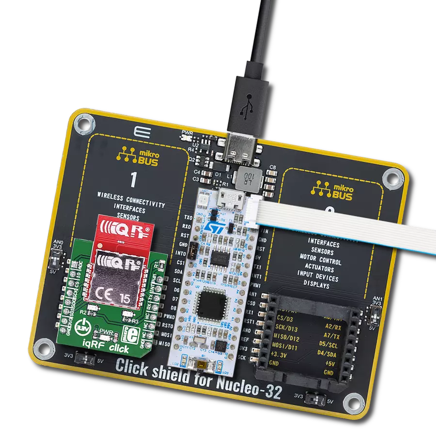
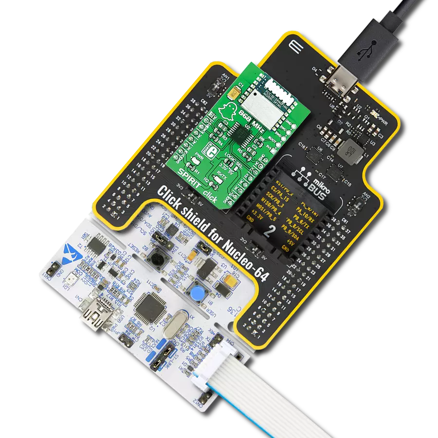
Click Shield for Nucleo-32 is the perfect way to expand your development board's functionalities with STM32 Nucleo-32 pinout. The Click Shield for Nucleo-32 provides two mikroBUS™ sockets to add any functionality from our ever-growing range of Click boards™. We are fully stocked with everything, from sensors and WiFi transceivers to motor control and audio amplifiers. The Click Shield for Nucleo-32 is compatible with the STM32 Nucleo-32 board, providing an affordable and flexible way for users to try out new ideas and quickly create prototypes with any STM32 microcontrollers, choosing from the various combinations of performance, power consumption, and features. The STM32 Nucleo-32 boards do not require any separate probe as they integrate the ST-LINK/V2-1 debugger/programmer and come with the STM32 comprehensive software HAL library and various packaged software examples. This development platform provides users with an effortless and common way to combine the STM32 Nucleo-32 footprint compatible board with their favorite Click boards™ in their upcoming projects.

Used MCU Pins
mikroBUS™ mapper
Take a closer look
Click board™ Schematic

Step by step
Project assembly

Start by selecting your development board and Click board™. Begin with the Nucleo 32 with STM32F031K6 MCU as your development board.


Software Support
Library Description
This library contains API for EnOcean 3 Click driver.
Key functions:
enocean3_uart_isr- UART Interrupt Routine function.enocean3_response_handler_set- Handler Set function.enocean3_send_packet- Packet Send function.
Open Source
Code example
The complete application code and a ready-to-use project are available through the NECTO Studio Package Manager for direct installation in the NECTO Studio. The application code can also be found on the MIKROE GitHub account.
/*!
 * \file
 * \brief Enocean3 Click example
 *
 * # Description
 * This example reads and processes data from EnOcean 3 Clicks.
 *
 * The demo application is composed of two sections :
 *
 * ## Application Init
 * Initializes the driver and sets the driver handler.
 *
 * ## Application Task
 * Reads the received data and parses it on the USB UART if the response buffer is ready.
 *
 * ## Additional Function
 * - enocean3_process - The general process of collecting data the module sends.
 * - make_response - Driver handler function which stores data in the response buffer.
 * - log_response - Logs the module response on the USB UART.
 * - log_example - Logs button events on the USB UART.
 * - check_response - Checks if the response is ready and logs button events.
 *
 * \author MikroE Team
 *
 */
// ------------------------------------------------------------------- INCLUDES

#include "board.h"
#include "log.h"
#include "enocean3.h"
#include "string.h"

// ------------------------------------------------------------------ VARIABLES

static enocean3_t enocean3;
static log_t logger;

enocean3_packet_t response;
uint16_t response_size_cnt;
uint8_t rsp_check;

// ------------------------------------------------------- ADDITIONAL FUNCTIONS

void make_response( enocean3_packet_t *rsp, uint16_t *rsp_length_size )
{
    uint16_t rsp_cnt;

    for ( rsp_cnt = 0; rsp_cnt < rsp->data_length; rsp_cnt++ )
    {
        response.data_buff[ rsp_cnt ] = rsp->data_buff[ rsp_cnt ];
    }

    response.data_length = rsp->data_length;
    response.opt_length  = rsp->opt_length;
    response.packet_type = rsp->packet_type;
    response_size_cnt    = *rsp_length_size;
}

void log_response( )
{
    uint16_t rsp_cnt;

    if ( rsp_check == 1 )
    {
        log_printf( &logger, "OPCODE + PARAM : ", rsp_check );
        rsp_check = 0;
    }

    for ( rsp_cnt = 0; rsp_cnt < response.data_length; rsp_cnt++ )
    {
        log_printf( &logger, "0x%.2X ", ( uint16_t ) response.data_buff[ rsp_cnt ] );
    }

    if ( response_size_cnt == 1 )
    {
        log_printf( &logger, "\r\n" );
        rsp_check = 1;
    }
}

void log_example( )
{
    switch ( response.data_buff[ 1 ] )
    {
        case 0x00:
        {
            log_printf( &logger, "* Button is released *\r\n" );
            break;
        }
        case 0x10 :
        {
            log_printf( &logger, "* Button 1 is pressed *\r\n" );
            break;
        }
        case 0x30 :
        {
            log_printf( &logger, "* Button 3 is pressed *\r\n" );
            break;
        }
        case 0x50 :
        {
            log_printf( &logger, "* Button 5 is pressed *\r\n" );
            break;
        }
        case 0x70 :
        {
            log_printf( &logger, "* Button 7 is pressed *\r\n" );
            break;
        }
        case 0x15 :
        {
            log_printf( &logger, "* Buttons 1 and 5 are pressed *\r\n" );
            break;
        }
        case 0x17 :
        {
            log_printf( &logger, "* Buttons 1 and 7 are pressed *\r\n" );
            break;
        }
        case 0x35 :
        {
            log_printf( &logger, "* Buttons 3 and 5 are pressed *\r\n" );
            break;
        }
        case 0x37 :
        {
            log_printf( &logger, "* Buttons 3 and 7 are pressed *\r\n" );
            break;
        }
        default :
        {
            break;
        }
    }
}

void check_response( )
{
    uint8_t response_ready;

    response_ready = enocean3_response_ready( &enocean3 );

    if ( response_ready == ENOCEAN3_RESPONSE_READY )
    {
        log_example( );
    }
}

// ------------------------------------------------------ APPLICATION FUNCTIONS

void application_init ( void )
{
    log_cfg_t log_cfg;
    enocean3_cfg_t cfg;

    /**
     * Logger initialization.
     * Default baud rate: 115200
     * Default log level: LOG_LEVEL_DEBUG
     * @note If USB_UART_RX and USB_UART_TX
     * are defined as HAL_PIN_NC, you will
     * need to define them manually for log to work.
     * See @b LOG_MAP_USB_UART macro definition for detailed explanation.
     */
    LOG_MAP_USB_UART( log_cfg );
    log_init( &logger, &log_cfg );
    log_info( &logger, "---- Application Init ----" );

    //  Click initialization.

    enocean3_cfg_setup( &cfg );
    ENOCEAN3_MAP_MIKROBUS( cfg, MIKROBUS_1 );
    enocean3_init( &enocean3, &cfg );

    Delay_ms ( 500 );

    enocean3_response_handler_set( &enocean3, &make_response );
    rsp_check = 1;
}

void application_task ( void )
{
    enocean3_uart_isr ( &enocean3 );
    check_response ( );
    Delay_1ms( );
}

int main ( void )
{
    /* Do not remove this line or clock might not be set correctly. */
    #ifdef PREINIT_SUPPORTED
    preinit();
    #endif

    application_init( );

    for ( ; ; )
    {
        application_task( );
    }

    return 0;
}


// ------------------------------------------------------------------------ END
Additional Support
Resources
Category:Sub-1 GHz Transceievers