Create a versatile solution for connecting and controlling various peripherals with MAX7300 and STM32F031K6
Expand and conquer: I/O magic for your projects!
Published Oct 01, 2024
Click board™
Expand 12 Click
Dev. board
Nucleo 32 with STM32F031K6 MCU
Compiler
NECTO Studio
MCU
STM32F031K6
Empower industrial automation systems and embedded solutions with our I/O expander, providing a compact and versatile solution for expanding input and output capabilities
A
A
Hardware Overview
How does it work?
Expand 12 Click is based on the MAX7300, a general-purpose input/output (GPIO) expander from Analog Devices, now part of Analog Devices. This port expander is a simple solution when additional I/Os are needed while keeping interconnections to a minimum. It is particularly great for system monitoring applications, industrial controllers, and portable equipment. The MAX7300 comes in a 28-port configuration, which can be configured to any combination of logic inputs and logic outputs and default to logic inputs on Power-Up. Any I/O port can be configured as a push-pull output (sinking 10mA,
sourcing 4.5mA) or a Schmitt-trigger logic input. Each input has an individually selectable internal pull-up resistor. Additionally, transition detection allows seven ports (from port 24 up to port 30) to be monitored in any maskable combination for changes in their logic status. A detected transition is flagged through a status register bit and an interrupt pin (port 31) if desired. Expand 12 Click communicates with MCU using the standard I2C 2-Wire interface to read data and configure settings with a maximum frequency of 400kHz. Besides, it also allows the choice of the least significant bit of its I2C slave address by
positioning the SMD jumpers labeled ADDR SEL to an appropriate position marked as 1 and 0. This way, the MAX7300 provides the opportunity of the 16 possible different I2C addresses by positioning the SMD jumper to an appropriate position. This Click board™ can operate with either 3.3V or 5V logic voltage levels selected via the VCC SEL jumper. This way, both 3.3V and 5V capable MCUs can use the communication lines properly. Also, this Click board™ comes equipped with a library containing easy-to-use functions and an example code that can be used as a reference for further development.


Features overview
Development board
Nucleo 32 with STM32F031K6 MCU board provides an affordable and flexible platform for experimenting with STM32 microcontrollers in 32-pin packages. Featuring Arduino™ Nano connectivity, it allows easy expansion with specialized shields, while being mbed-enabled for seamless integration with online resources. The
board includes an on-board ST-LINK/V2-1 debugger/programmer, supporting USB reenumeration with three interfaces: Virtual Com port, mass storage, and debug port. It offers a flexible power supply through either USB VBUS or an external source. Additionally, it includes three LEDs (LD1 for USB communication, LD2 for power,
and LD3 as a user LED) and a reset push button. The STM32 Nucleo-32 board is supported by various Integrated Development Environments (IDEs) such as IAR™, Keil®, and GCC-based IDEs like AC6 SW4STM32, making it a versatile tool for developers.

Microcontroller Overview
MCU Card / MCU

Architecture
ARM Cortex-M0
MCU Memory (KB)
32
Silicon Vendor
STMicroelectronics
Pin count
32
RAM (Bytes)
4096
You complete me!
Accessories
Click Shield for Nucleo-32 is the perfect way to expand your development board's functionalities with STM32 Nucleo-32 pinout. The Click Shield for Nucleo-32 provides two mikroBUS™ sockets to add any functionality from our ever-growing range of Click boards™. We are fully stocked with everything, from sensors and WiFi transceivers to motor control and audio amplifiers. The Click Shield for Nucleo-32 is compatible with the STM32 Nucleo-32 board, providing an affordable and flexible way for users to try out new ideas and quickly create prototypes with any STM32 microcontrollers, choosing from the various combinations of performance, power consumption, and features. The STM32 Nucleo-32 boards do not require any separate probe as they integrate the ST-LINK/V2-1 debugger/programmer and come with the STM32 comprehensive software HAL library and various packaged software examples. This development platform provides users with an effortless and common way to combine the STM32 Nucleo-32 footprint compatible board with their favorite Click boards™ in their upcoming projects.

Used MCU Pins
mikroBUS™ mapper
Take a closer look
Click board™ Schematic

Step by step
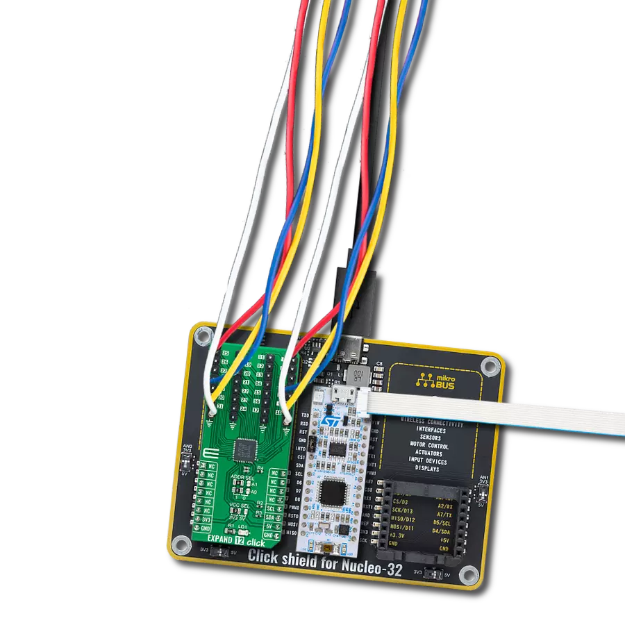
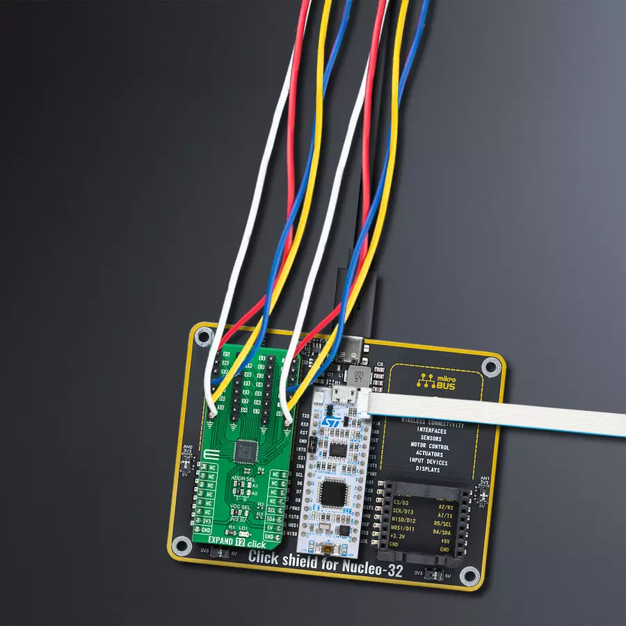
Project assembly

Start by selecting your development board and Click board™. Begin with the Nucleo 32 with STM32F031K6 MCU as your development board.


Track your results in real time
Application Output
1. Application Output - In Debug mode, the 'Application Output' window enables real-time data monitoring, offering direct insight into execution results. Ensure proper data display by configuring the environment correctly using the provided tutorial.

2. UART Terminal - Use the UART Terminal to monitor data transmission via a USB to UART converter, allowing direct communication between the Click board™ and your development system. Configure the baud rate and other serial settings according to your project's requirements to ensure proper functionality. For step-by-step setup instructions, refer to the provided tutorial.

3. Plot Output - The Plot feature offers a powerful way to visualize real-time sensor data, enabling trend analysis, debugging, and comparison of multiple data points. To set it up correctly, follow the provided tutorial, which includes a step-by-step example of using the Plot feature to display Click board™ readings. To use the Plot feature in your code, use the function: plot(*insert_graph_name*, variable_name);. This is a general format, and it is up to the user to replace 'insert_graph_name' with the actual graph name and 'variable_name' with the parameter to be displayed.

Software Support
Library Description
This library contains API for Expand 12 Click driver.
Key functions:
expand12_set_pin_direction- This function sets the direction of the selected pinexpand12_set_pin_value- This function sets the logic level of the selected pinexpand12_read_all_pins_value- This function reads all pins logic levels
Open Source
Code example
The complete application code and a ready-to-use project are available through the NECTO Studio Package Manager for direct installation in the NECTO Studio. The application code can also be found on the MIKROE GitHub account.
/*!
 * @file main.c
 * @brief Expand12 Click example
 *
 * # Description
 * This example demonstrates the use of Expand 12 Click board.
 *
 * The demo application is composed of two sections :
 *
 * ## Application Init
 * Initializes the driver and performs the Click default configuration which sets
 * the first three ports (pins 4-23) as output and the fourth port (pins 24-31) as input with pull-ups.
 *
 * ## Application Task
 * Sets the pins of the first three ports and then reads the status of all pins and
 * displays the result on the USB UART approximately every 100 miliseconds.
 *
 * @author Stefan Filipovic
 *
 */

#include "board.h"
#include "log.h"
#include "expand12.h"

static expand12_t expand12;
static log_t logger;

void application_init ( void )
{
    log_cfg_t log_cfg;  /**< Logger config object. */
    expand12_cfg_t expand12_cfg;  /**< Click config object. */

    /**
     * Logger initialization.
     * Default baud rate: 115200
     * Default log level: LOG_LEVEL_DEBUG
     * @note If USB_UART_RX and USB_UART_TX
     * are defined as HAL_PIN_NC, you will
     * need to define them manually for log to work.
     * See @b LOG_MAP_USB_UART macro definition for detailed explanation.
     */
    LOG_MAP_USB_UART( log_cfg );
    log_init( &logger, &log_cfg );
    log_info( &logger, " Application Init " );

    // Click initialization.
    expand12_cfg_setup( &expand12_cfg );
    EXPAND12_MAP_MIKROBUS( expand12_cfg, MIKROBUS_1 );
    if ( I2C_MASTER_ERROR == expand12_init( &expand12, &expand12_cfg ) )
    {
        log_error( &logger, " Communication init." );
        for ( ; ; );
    }

    if ( EXPAND12_ERROR == expand12_default_cfg ( &expand12 ) )
    {
        log_error( &logger, " Default configuration." );
        for ( ; ; );
    }

    log_info( &logger, " Application Task " );
}

void application_task ( void )
{
    static uint8_t port_value = 0;
    static uint32_t pins_status = 0;

    expand12_set_port_value( &expand12, EXPAND12_PORT_4_7, EXPAND12_ALL_PINS, port_value );
    expand12_set_port_value( &expand12, EXPAND12_PORT_8_15, EXPAND12_ALL_PINS, port_value );
    expand12_set_port_value( &expand12, EXPAND12_PORT_16_23, EXPAND12_ALL_PINS, port_value++ );

    expand12_read_all_pins_value( &expand12, &pins_status );
    log_printf( &logger, " Pins status (32-bit) : 0x%.8LX\r\n\n", pins_status );
    Delay_ms ( 100 );
}

int main ( void )
{
    /* Do not remove this line or clock might not be set correctly. */
    #ifdef PREINIT_SUPPORTED
    preinit();
    #endif

    application_init( );

    for ( ; ; )
    {
        application_task( );
    }

    return 0;
}

// ------------------------------------------------------------------------ END