Transform the way of data acquisition management and control with PI4IOE5V96248 and STM32F031K6
One device, many ports: I/O expansion at your fingertips!

Published Oct 01, 2024
Click board™
Expand 13 Click
Dev. board
Nucleo 32 with STM32F031K6 MCU
Compiler
NECTO Studio
MCU
STM32F031K6
Elevate the performance of your automation projects with our multi-port I/O expander, ensuring seamless and synchronized data exchange among various input and output devices
A
A
Hardware Overview
How does it work?
Expand 13 Click is based on the PI4IOE5V96248, a 48-bit low-voltage translating general-purpose remote I/O expander from Diodes Incorporated. This port expander is a simple solution when additional I/Os are needed while keeping interconnections to a minimum. It is particularly great for system monitoring applications, industrial controllers, and portable equipment. The PI4IOE5V96248 comes in a 6-channel configuration with a built-in level shifting feature that makes it highly flexible in power supply systems where communication between incompatible I/O voltages is required. The PI4IOE5V96248 has low current consumption and includes latched outputs with high current drive capability for directly driving LEDs. All ports of the PI4IOE5V96248 are entirely independent and can
be used as input or output ports without using a control signal for data directions. Input data is transferred from the ports to the MCU in the Read mode, while output data is transmitted to the ports in the Write mode, where every data transmission must consist of a multiple of six bytes. Expand 13 Click communicates with MCU using the standard I2C 2-Wire interface to read data and configure settings with a maximum frequency of 1MHz. Besides, it also allows the choice of the least significant bit of its I2C slave address by positioning the SMD jumpers labeled ADDR SEL to an appropriate position marked as 0 and 1. This way, the PI4IOE5V96248 provides the opportunity of the 64 possible different I2C addresses by positioning the SMD jumper to an appropriate position. In addition to I2C
communication, two GPIO pins connected to the mikroBUS™ socket pins are also used. The Reset pin routed to the RST pin of the mikroBUS™ socket, is used to place the PI4IOE5V96248 registers in their default state, while the interrupt, routed to the INT pin of the mikroBUS™ socket, may be configured as an interrupt to notify the host MCU of incoming data on any port without having to communicate via the I2C-bus. This Click board™ can operate with either 3.3V or 5V logic voltage levels selected via the VCC SEL jumper. This way, both 3.3V and 5V capable MCUs can use the communication lines properly. Also, this Click board™ comes equipped with a library containing easy-to-use functions and an example code that can be used as a reference for further development.


Features overview
Development board
Nucleo 32 with STM32F031K6 MCU board provides an affordable and flexible platform for experimenting with STM32 microcontrollers in 32-pin packages. Featuring Arduino™ Nano connectivity, it allows easy expansion with specialized shields, while being mbed-enabled for seamless integration with online resources. The
board includes an on-board ST-LINK/V2-1 debugger/programmer, supporting USB reenumeration with three interfaces: Virtual Com port, mass storage, and debug port. It offers a flexible power supply through either USB VBUS or an external source. Additionally, it includes three LEDs (LD1 for USB communication, LD2 for power,
and LD3 as a user LED) and a reset push button. The STM32 Nucleo-32 board is supported by various Integrated Development Environments (IDEs) such as IAR™, Keil®, and GCC-based IDEs like AC6 SW4STM32, making it a versatile tool for developers.

Microcontroller Overview
MCU Card / MCU

Architecture
ARM Cortex-M0
MCU Memory (KB)
32
Silicon Vendor
STMicroelectronics
Pin count
32
RAM (Bytes)
4096
You complete me!
Accessories
Click Shield for Nucleo-32 is the perfect way to expand your development board's functionalities with STM32 Nucleo-32 pinout. The Click Shield for Nucleo-32 provides two mikroBUS™ sockets to add any functionality from our ever-growing range of Click boards™. We are fully stocked with everything, from sensors and WiFi transceivers to motor control and audio amplifiers. The Click Shield for Nucleo-32 is compatible with the STM32 Nucleo-32 board, providing an affordable and flexible way for users to try out new ideas and quickly create prototypes with any STM32 microcontrollers, choosing from the various combinations of performance, power consumption, and features. The STM32 Nucleo-32 boards do not require any separate probe as they integrate the ST-LINK/V2-1 debugger/programmer and come with the STM32 comprehensive software HAL library and various packaged software examples. This development platform provides users with an effortless and common way to combine the STM32 Nucleo-32 footprint compatible board with their favorite Click boards™ in their upcoming projects.

Used MCU Pins
mikroBUS™ mapper
Take a closer look
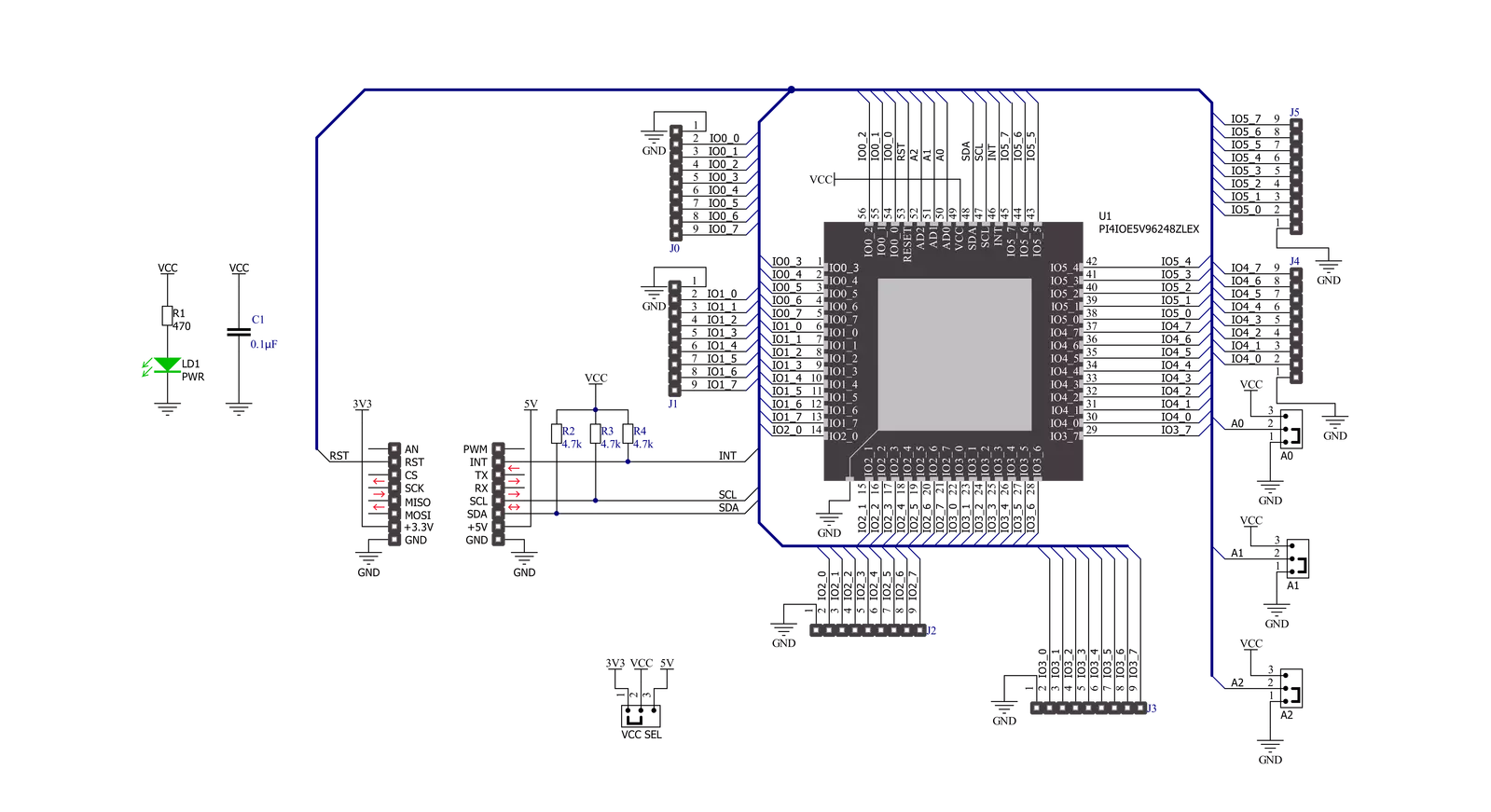
Click board™ Schematic
Step by step
Project assembly

Start by selecting your development board and Click board™. Begin with the Nucleo 32 with STM32F031K6 MCU as your development board.


Software Support
Library Description
This library contains API for Expand 13 Click driver.
Key functions:
expand13_enable_device- This function enables the device by setting the RST pin to high logic stateexpand13_write_all_ports- This function writes a desired data to all 6 portsexpand13_read_all_ports- This function reads the state of all 6 ports
Open Source
Code example
The complete application code and a ready-to-use project are available through the NECTO Studio Package Manager for direct installation in the NECTO Studio. The application code can also be found on the MIKROE GitHub account.
/*!
 * @file main.c
 * @brief Expand13 Click example
 *
 * # Description
 * This example demonstrates the use of Expand 13 Click board,
 * by writing data to all six ports and then reading back the status of the ports.
 *
 * The demo application is composed of two sections :
 *
 * ## Application Init
 * Initializes the driver and enables the Click board.
 *
 * ## Application Task
 * Sets the pins of all ports and then reads and displays their status on the
 * USB UART approximately once per second.
 *
 * @author Stefan Filipovic
 *
 */

#include "board.h"
#include "log.h"
#include "expand13.h"

static expand13_t expand13;
static log_t logger;

void application_init ( void )
{
    log_cfg_t log_cfg;  /**< Logger config object. */
    expand13_cfg_t expand13_cfg;  /**< Click config object. */

    /**
     * Logger initialization.
     * Default baud rate: 115200
     * Default log level: LOG_LEVEL_DEBUG
     * @note If USB_UART_RX and USB_UART_TX
     * are defined as HAL_PIN_NC, you will
     * need to define them manually for log to work.
     * See @b LOG_MAP_USB_UART macro definition for detailed explanation.
     */
    LOG_MAP_USB_UART( log_cfg );
    log_init( &logger, &log_cfg );
    log_info( &logger, " Application Init " );

    // Click initialization.
    expand13_cfg_setup( &expand13_cfg );
    EXPAND13_MAP_MIKROBUS( expand13_cfg, MIKROBUS_1 );
    if ( I2C_MASTER_ERROR == expand13_init( &expand13, &expand13_cfg ) )
    {
        log_error( &logger, " Communication init." );
        for ( ; ; );
    }
    expand13_enable_device ( &expand13 );
    log_info( &logger, " Application Task " );
}

void application_task ( void )
{
    uint8_t port_value[ 6 ] = { 0 };
    uint16_t pin_num = 0;

    for ( pin_num = EXPAND13_PIN_0_MASK; pin_num <= EXPAND13_PIN_7_MASK; pin_num <<= 1 )
    {
        if ( !expand13_get_int_pin ( &expand13 ) )
        {
            log_printf( &logger, " External input has occurred.\r\n" );
        }

        memset ( port_value, pin_num, 6 );
        expand13_write_all_ports( &expand13, port_value );

        expand13_read_all_ports( &expand13, port_value );
        for ( uint8_t cnt = EXPAND13_PORT_0; cnt <= EXPAND13_PORT_5; cnt++ )
        {
            log_printf( &logger, " Status port %d : 0x%.2X\r\n", ( uint16_t ) cnt, ( uint16_t ) port_value[ cnt ] );
        }
        log_printf( &logger, "\n" );
        Delay_ms ( 1000 );
    }
}

int main ( void )
{
    /* Do not remove this line or clock might not be set correctly. */
    #ifdef PREINIT_SUPPORTED
    preinit();
    #endif

    application_init( );

    for ( ; ; )
    {
        application_task( );
    }

    return 0;
}

// ------------------------------------------------------------------------ END
Additional Support
Resources
Category:Port expander


