Improve your comfort with EMS2301 and STM32F031K6
Your fan's best friend

Published Oct 01, 2024
Click board™
Fan Click
Dev. board
Nucleo 32 with STM32F031K6 MCU
Compiler
NECTO Studio
MCU
STM32F031K6
Find your perfect balance with our fan speed solution
A
A
Hardware Overview
How does it work?
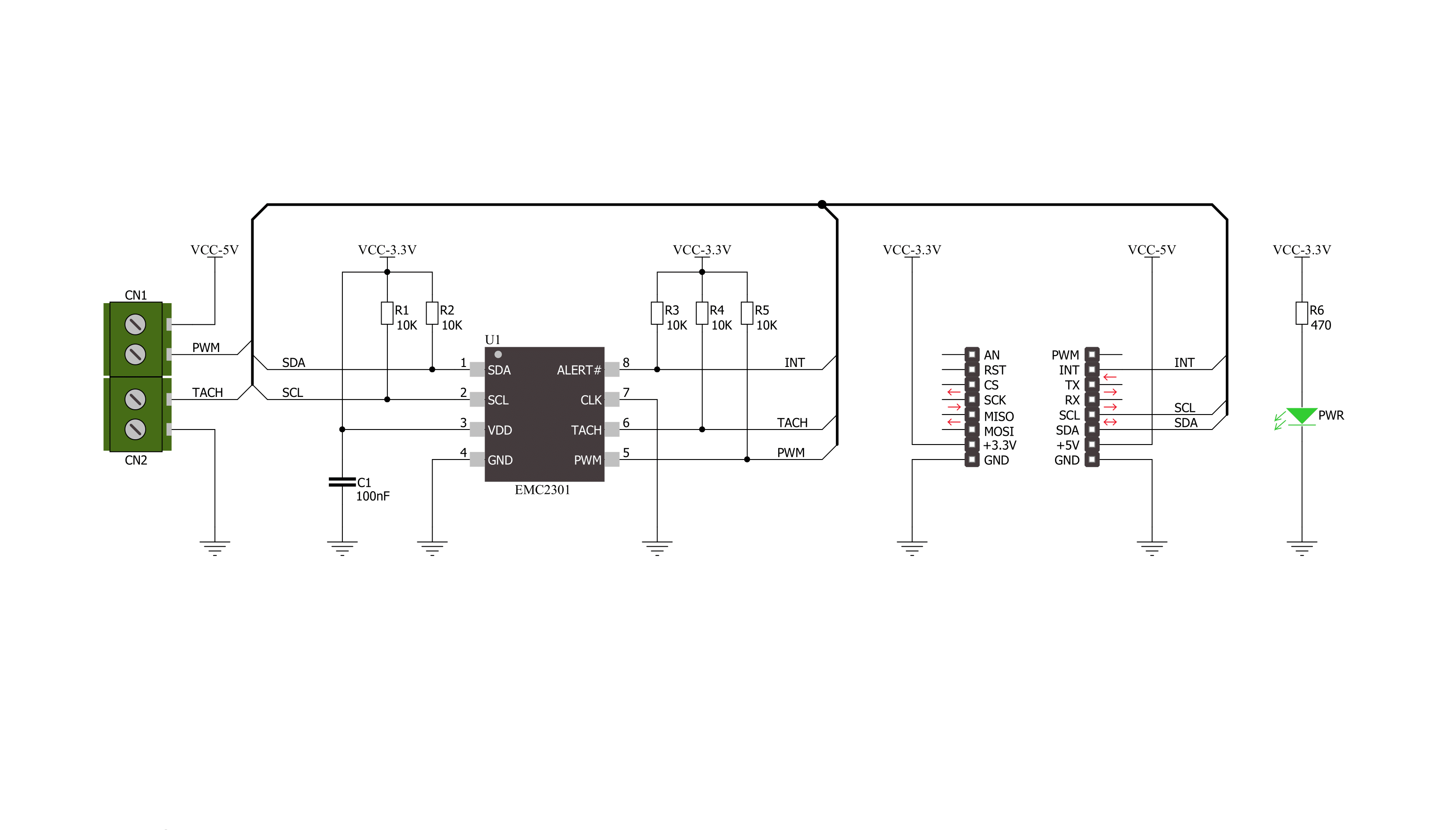
Fan Click is based on the EMS2301, a single/multiple RPM-based PWM fan controller from Microchip. The EMS2301 uses a programmable frequency driver and RPM-based algorithm with an internal clock to allow you to regulate the RPM of a given fan with 1% accuracy from 500 to 16K RPM. It also provides tachometer feedback for fan speed control available on TACH onboard terminal. The Fan Click can operate in either a closed-loop fashion or as a directly PWM-controlled device. In a closed loop, the Fan Speed Control (FSC) algorithm can detect aging, stalled, or locked fans and will trigger an interrupt.
In the FSC mode user determines a target tachometer count, and the PWM drive setting is automatically updated to achieve this target speed. This Click board™ communicates with MCU using the standard I2C 2-Wire interface to read data and configure settings, supporting a Fast Mode operation up to 400kHz. The EMS2301 monitors the fans' tachometer signals to detect fan failure, and when the tachometer count is larger than the fan tachometer limit, the fan is considered failing. If that happens, the alert is triggered over the interrupt INT pin. Meanwhile, the fan driver attempts to alleviate a Stalled/Stack
fan condition. Although a 3.3V voltage level only, this Click board™ uses a 5V rail to power a 4-wire fan over a 4-pin screw terminal. This board does not support an external power supply for the fan. This Click board™ can only be operated with a 3.3V logic voltage level. The board must perform appropriate logic voltage level conversion before using MCUs with different logic levels. This Click board™ comes equipped with a library containing functions and an example code that can be used as a reference for further development.

Features overview
Development board
Nucleo 32 with STM32F031K6 MCU board provides an affordable and flexible platform for experimenting with STM32 microcontrollers in 32-pin packages. Featuring Arduino™ Nano connectivity, it allows easy expansion with specialized shields, while being mbed-enabled for seamless integration with online resources. The
board includes an on-board ST-LINK/V2-1 debugger/programmer, supporting USB reenumeration with three interfaces: Virtual Com port, mass storage, and debug port. It offers a flexible power supply through either USB VBUS or an external source. Additionally, it includes three LEDs (LD1 for USB communication, LD2 for power,
and LD3 as a user LED) and a reset push button. The STM32 Nucleo-32 board is supported by various Integrated Development Environments (IDEs) such as IAR™, Keil®, and GCC-based IDEs like AC6 SW4STM32, making it a versatile tool for developers.

Microcontroller Overview
MCU Card / MCU

Architecture
ARM Cortex-M0
MCU Memory (KB)
32
Silicon Vendor
STMicroelectronics
Pin count
32
RAM (Bytes)
4096
You complete me!
Accessories
Click Shield for Nucleo-32 is the perfect way to expand your development board's functionalities with STM32 Nucleo-32 pinout. The Click Shield for Nucleo-32 provides two mikroBUS™ sockets to add any functionality from our ever-growing range of Click boards™. We are fully stocked with everything, from sensors and WiFi transceivers to motor control and audio amplifiers. The Click Shield for Nucleo-32 is compatible with the STM32 Nucleo-32 board, providing an affordable and flexible way for users to try out new ideas and quickly create prototypes with any STM32 microcontrollers, choosing from the various combinations of performance, power consumption, and features. The STM32 Nucleo-32 boards do not require any separate probe as they integrate the ST-LINK/V2-1 debugger/programmer and come with the STM32 comprehensive software HAL library and various packaged software examples. This development platform provides users with an effortless and common way to combine the STM32 Nucleo-32 footprint compatible board with their favorite Click boards™ in their upcoming projects.

Used MCU Pins
mikroBUS™ mapper
Take a closer look
Click board™ Schematic
Step by step
Project assembly

Start by selecting your development board and Click board™. Begin with the Nucleo 32 with STM32F031K6 MCU as your development board.


Track your results in real time
Application Output
1. Application Output - In Debug mode, the 'Application Output' window enables real-time data monitoring, offering direct insight into execution results. Ensure proper data display by configuring the environment correctly using the provided tutorial.

2. UART Terminal - Use the UART Terminal to monitor data transmission via a USB to UART converter, allowing direct communication between the Click board™ and your development system. Configure the baud rate and other serial settings according to your project's requirements to ensure proper functionality. For step-by-step setup instructions, refer to the provided tutorial.

3. Plot Output - The Plot feature offers a powerful way to visualize real-time sensor data, enabling trend analysis, debugging, and comparison of multiple data points. To set it up correctly, follow the provided tutorial, which includes a step-by-step example of using the Plot feature to display Click board™ readings. To use the Plot feature in your code, use the function: plot(*insert_graph_name*, variable_name);. This is a general format, and it is up to the user to replace 'insert_graph_name' with the actual graph name and 'variable_name' with the parameter to be displayed.

Software Support
Library Description
This library contains API for Fan Click driver.
Key functions:
fan_generic_write- Generic write functionfan_generic_read- Generic read functionfan_lock_registers- Fan click lock registers
Open Source
Code example
The complete application code and a ready-to-use project are available through the NECTO Studio Package Manager for direct installation in the NECTO Studio. The application code can also be found on the MIKROE GitHub account.
/*!
 * \file main.c
 * \brief Fan Click Example
 *
 * # Description
 * This application is controller for powering and regulating of fan.
 *
 * The demo application is composed of two sections :
 *
 * ## Application Init
 * Initialization of Click driver and usb uart serial terminal for results
 * logging.
 *
 * ## Application Task
 * Performs a control of the fan and reads rotation per minute (RPM).
 * Results will be sent to the usb uart terminal.
 *
 * \author Nemanja Medakovic
 *
 */
// ------------------------------------------------------------------- INCLUDES

#include "board.h"
#include "log.h"
#include "fan.h"


#define FAN_DUTY_RATIO_0_PER    0       /**< PWM duty ratio 0 pecrents - zero scale. >*/
#define FAN_DUTY_RATIO_10_PER   10      /**< PWM duty ratio 10 percents - step. >*/
#define FAN_DUTY_RATIO_100_PER  100     /**< PWM duty ratio 100 percents - full scale. >*/

#define FAN_PWM_BASE_FREQ_ZERO_SCALE  0x00  /**< PWM base frequency zero scale. >*/
#define FAN_PWM_BASE_FREQ_HALF_SCALE  0x80  /**< PWM base frequency half scale. >*/
#define FAN_PWM_BASE_FREQ_FULL_SCALE  0xFF  /**< PWM base frequency full scale. >*/

// ------------------------------------------------------------------ VARIABLES

static fan_t fan;       /**< Fan Click object. >*/
static log_t logger;    /**< Logger object. >*/

// ------------------------------------------------------ APPLICATION FUNCTIONS

void application_init ( void )
{
    log_cfg_t log_cfg;
    fan_cfg_t fan_cfg;

    /**
     * Logger initialization.
     * Default baud rate: 115200
     * Default log level: LOG_LEVEL_DEBUG
     * @note If USB_UART_RX and USB_UART_TX
     * are defined as HAL_PIN_NC, you will
     * need to define them manually for log to work.
     * See @b LOG_MAP_USB_UART macro definition for detailed explanation.
     */
    LOG_MAP_USB_UART( log_cfg );
    log_init( &logger, &log_cfg );
    log_info( &logger, "---- Application Init ----" );

    //  Click initialization.

    fan_cfg_setup( &fan_cfg );
    FAN_MAP_MIKROBUS( fan_cfg, MIKROBUS_1 );
    if ( fan_init( &fan, &fan_cfg ) == I2C_MASTER_ERROR )
    {
        log_info( &logger, "---- Application Init Error ----" );
        log_info( &logger, "---- Please, run program again ----" );

        for ( ; ; );
    }
    log_info( &logger, "---- Application Init Done ----" );
    fan_default_cfg( &fan );
    fan_pwm_base( &fan, FAN_PWM_BASE_FREQ_HALF_SCALE );
    log_info( &logger, "---- Application Program Running... ----\n" );
}

void application_task ( void )
{
    for ( uint8_t duty = FAN_DUTY_RATIO_0_PER; duty <= FAN_DUTY_RATIO_100_PER;
          duty += FAN_DUTY_RATIO_10_PER )
    {
        fan_setting( &fan, duty );
        log_printf( &logger, " Duty Ratio : %u%%\r\n", (uint16_t)duty );
        Delay_ms ( 1000 );
        Delay_ms ( 1000 );

        uint16_t tacho = 0;

        fan_get_tach( &fan, &tacho );
        log_printf( &logger, " Rotation per minute : %urpm\r\n\n", tacho );
        Delay_ms ( 1000 );
        Delay_ms ( 1000 );
    }
}

int main ( void )
{
    /* Do not remove this line or clock might not be set correctly. */
    #ifdef PREINIT_SUPPORTED
    preinit();
    #endif

    application_init( );

    for ( ; ; )
    {
        application_task( );
    }

    return 0;
}

// ------------------------------------------------------------------------ END


