Discover the future of location technology through STM32F031K6 and LC79DA
Guiding your journey, down to the last detail

Published Oct 01, 2024
Click board™
GNSS 8 Click
Dev. board
Nucleo 32 with STM32F031K6 MCU
Compiler
NECTO Studio
MCU
STM32F031K6
Embark on journeys with unwavering confidence, thanks to our GNSS solution's exceptional accuracy
A
A
Hardware Overview
How does it work?
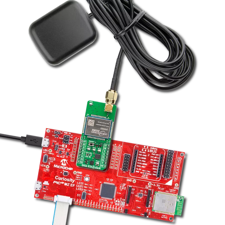
GNSS 8 Click is based on the LC79DA, a high-performance dual-band and multi-constellation GNSS module from Quectel Wireless Solutions. It supports L1 and L5 bands for GPS, Galileo, and QZSS, the L1 band for GLONASS and BeiDou, and the L5 band for IRNSS. Compared with the GNSS modules working on the L1 band only, LC79DA dramatically increases the number of satellites involved in tracking and positioning, reducing signal acquisition time and improving positioning accuracy even when the GNSS signal is absent or compromised. The LC79DA is AIS-140 compliant, and its onboard LNAs and SAW filters ensure better positioning under weak signal conditions and other harsh environments, providing better performance in anti-jamming. Besides Sleep and Standby operational modes, the LC79DA also has a Full-On mode that comprises tracking and acquisition modes. In acquisition mode, the module starts to search satellites and determine the visible satellites, coarse carrier frequency, and code phase of satellite signals. When the acquisition is completed, it will automatically switch to tracking mode. In tracking mode, the module tracks satellites and demodulates the navigation data from specific satellites. The LC79DA communicates with MCU using the UART interface with commonly used UART RX and TX pins as its default communication protocol. It
operates at 115200bps by default configuration to transmit and exchange data with the host MCU. It is also equipped with a USB type C connector, which allows the module to be powered and configured by a personal computer (PC) using FT230X, a compact USB to a serial UART interface bridge designed to operate efficiently with USB host controllers. Besides this bridge, it also possesses the RX/TX blue LED indicator, indicating whether it is in RX or TX mode. The users can also use another interface, such as I2C, to configure the module and write the library by themselves. The REQ pin routed on the RST pin of the mikroBUS™ represents data availability indication used to indicate whether there is data available for reading, while the INT pin on the mikroBUS™ socket represents a standard interrupt feature providing the user with feedback information. Next to these pins, this Click board™ also uses AP request to send pins labeled as APR, routed on the PWM pin of the mikroBUS™ socket, and RDY module status indication used with the APR pin. The high level of the APR pin notifies the module that the AP has data to be sent, and its low level means that data transfer has been completed, while RDY indicates whether the module is ready for communication with the AP. Also, this Click board™ has an additional yellow LED labeled as GNSS that shows one pulse per second
synchronized to GNSS satellites. An onboard pushbutton labeled BOOT represents the StartUp mode control button. Pressing the button for about 100ms during the Power-Up sequence, the LC79DA module will enter the host mode, allowing the users to perform firmware downloads successfully. After the module enters host mode successfully, release the BOOT button. BOOT mode can also be achieved with the external signal on the BOOT CTRL header in the same way as the button. In addition, the additional header labeled NSTB can be used to access the Standby mode and reset the module itself using an external signal. GNSS 8 Click possesses the SMA antenna connector with an impedance of 50Ω, which can connect the appropriate active antenna that Mikroe offers for improved range and received signal strength. This Click board™ can operate with both 3.3V and 5V MCUs. A proper logic voltage level conversion is performed by the appropriate voltage level translator TXS0108E, while the onboard LDO, the LT1965, ensures that the recommended voltage levels power module. However, the Click board™ comes equipped with a library containing easy-to-use functions and an example code that can be used as a reference for further development.

Features overview
Development board
Nucleo 32 with STM32F031K6 MCU board provides an affordable and flexible platform for experimenting with STM32 microcontrollers in 32-pin packages. Featuring Arduino™ Nano connectivity, it allows easy expansion with specialized shields, while being mbed-enabled for seamless integration with online resources. The
board includes an on-board ST-LINK/V2-1 debugger/programmer, supporting USB reenumeration with three interfaces: Virtual Com port, mass storage, and debug port. It offers a flexible power supply through either USB VBUS or an external source. Additionally, it includes three LEDs (LD1 for USB communication, LD2 for power,
and LD3 as a user LED) and a reset push button. The STM32 Nucleo-32 board is supported by various Integrated Development Environments (IDEs) such as IAR™, Keil®, and GCC-based IDEs like AC6 SW4STM32, making it a versatile tool for developers.

Microcontroller Overview
MCU Card / MCU

Architecture
ARM Cortex-M0
MCU Memory (KB)
32
Silicon Vendor
STMicroelectronics
Pin count
32
RAM (Bytes)
4096
You complete me!
Accessories
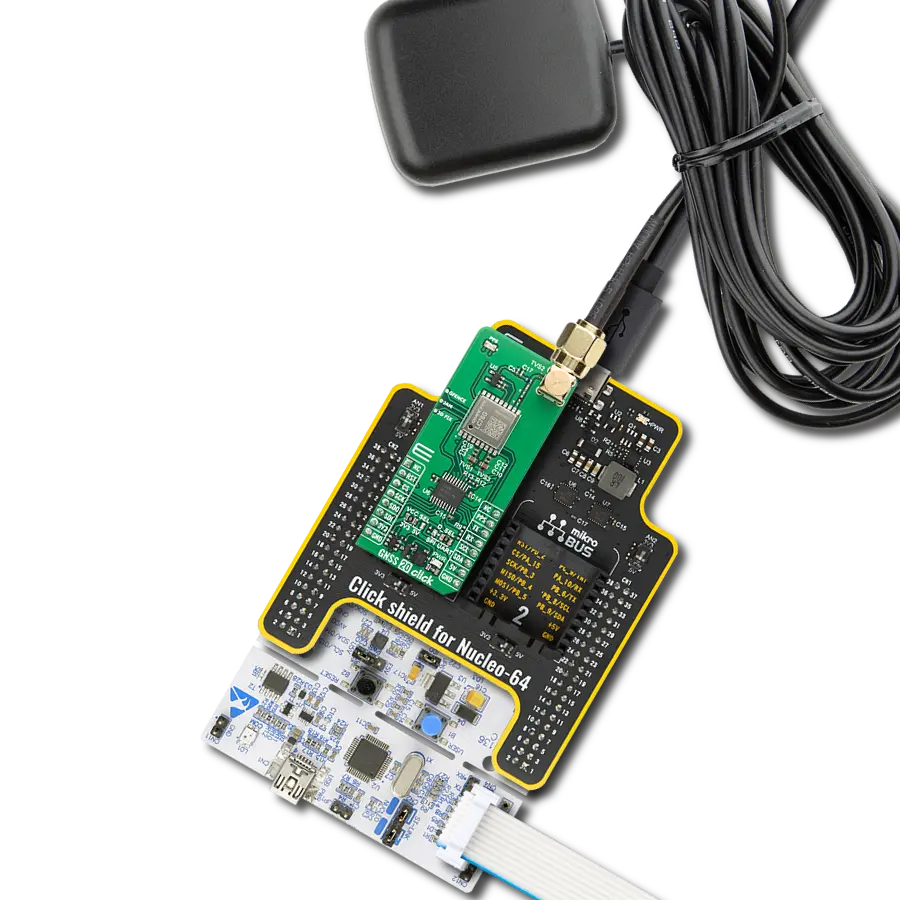
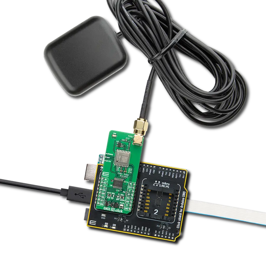
Click Shield for Nucleo-32 is the perfect way to expand your development board's functionalities with STM32 Nucleo-32 pinout. The Click Shield for Nucleo-32 provides two mikroBUS™ sockets to add any functionality from our ever-growing range of Click boards™. We are fully stocked with everything, from sensors and WiFi transceivers to motor control and audio amplifiers. The Click Shield for Nucleo-32 is compatible with the STM32 Nucleo-32 board, providing an affordable and flexible way for users to try out new ideas and quickly create prototypes with any STM32 microcontrollers, choosing from the various combinations of performance, power consumption, and features. The STM32 Nucleo-32 boards do not require any separate probe as they integrate the ST-LINK/V2-1 debugger/programmer and come with the STM32 comprehensive software HAL library and various packaged software examples. This development platform provides users with an effortless and common way to combine the STM32 Nucleo-32 footprint compatible board with their favorite Click boards™ in their upcoming projects.

GNSS L1/L5 Active External Antenna (YB0017AA) is an active patch antenna from Quectel that supports GNSS L1/L5 BD B1/B2 GLONASS L1, offering excellent performance with its high gain and efficiency for fleet management, navigation, RTK, and many other tracking applications. The magnetic-mounting antenna, with dimensions of 61.5×56.5×23mm, is designed to work with various ground plane sizes or in free space and is connected to the device by a 3m cable with an SMA male connector.

Used MCU Pins
mikroBUS™ mapper
Take a closer look
Click board™ Schematic

Step by step
Project assembly

Start by selecting your development board and Click board™. Begin with the Nucleo 32 with STM32F031K6 MCU as your development board.


Track your results in real time
Application Output
1. Application Output - In Debug mode, the 'Application Output' window enables real-time data monitoring, offering direct insight into execution results. Ensure proper data display by configuring the environment correctly using the provided tutorial.

2. UART Terminal - Use the UART Terminal to monitor data transmission via a USB to UART converter, allowing direct communication between the Click board™ and your development system. Configure the baud rate and other serial settings according to your project's requirements to ensure proper functionality. For step-by-step setup instructions, refer to the provided tutorial.

3. Plot Output - The Plot feature offers a powerful way to visualize real-time sensor data, enabling trend analysis, debugging, and comparison of multiple data points. To set it up correctly, follow the provided tutorial, which includes a step-by-step example of using the Plot feature to display Click board™ readings. To use the Plot feature in your code, use the function: plot(*insert_graph_name*, variable_name);. This is a general format, and it is up to the user to replace 'insert_graph_name' with the actual graph name and 'variable_name' with the parameter to be displayed.

Software Support
Library Description
This library contains API for GNSS 8 Click driver.
Key functions:
gnss8_generic_read- Data reading functiongnss8_generic_write- Data writing functiongnss8_set_ap_req- Set AP request pin state
Open Source
Code example
The complete application code and a ready-to-use project are available through the NECTO Studio Package Manager for direct installation in the NECTO Studio. The application code can also be found on the MIKROE GitHub account.
/*!
 * @file main.c
 * @brief GNSS 8 Click Example.
 *
 * # Description
 * This example showcases device abillity to read data outputed
 * from device and show it's coordinates and altitude when connected.
 *
 * The demo application is composed of two sections :
 *
 * ## Application Init
 * Initializes host communication modules, additioaln GPIO's used
 * for control of device and resets device.
 *
 * ## Application Task
 * Reads data from device and wait's untill device is connected.
 * While not connected it will log '.'. When conneceted and received
 * data for latitude, longitude, and altitude it will log that data
 * parsed from "GNGGA" command.
 *
 * ## Additional Function
 * - static void gnss8_clear_app_buf ( void )
 * - static err_t gnss8_process ( void )
 * - static err_t gnss8_cmd_parser ( char *cmd )
 *
 * @author Luka Filipovic
 *
 */

#include "board.h"
#include "log.h"
#include "gnss8.h"

#define PROCESS_BUFFER_SIZE                     700
#define DATA_BUFFER_SIZE                        30

#define RSP_GNGGA                               "GNGGA"
#define RSP_START                               '$'
#define RSP_SEPARATOR                           ','

#define RSP_GNGGA_LATITUDE_ELEMENT              2
#define RSP_GNGGA_LONGITUDE_ELEMENT             4
#define RSP_GNGGA_ALTITUDE_ELEMENT              9

static gnss8_t gnss8;
static log_t logger;

static char app_buf[ PROCESS_BUFFER_SIZE ]      = { 0 };
static int32_t app_buf_len                      = 0;
static int32_t app_buf_cnt                      = 0;

static char latitude_data[ DATA_BUFFER_SIZE ]   = { 0 };
static char longitude_data[ DATA_BUFFER_SIZE ]  = { 0 };
static char altitude_data[ DATA_BUFFER_SIZE ]   = { 0 };

err_t last_error_flag;

/**
 * @brief GNSS8 clearing application buffer.
 * @details This function clears memory of application buffer and reset it's length and counter.
 */
static void gnss8_clear_app_buf ( void );

/**
 * @brief GNSS8 data reading function.
 * @details This function reads data from device and concats data to application buffer.
 *
 * @return @li @c GNSS8_OK - Read some data.
 *         @li @c GNSS8_ERROR - Nothing is read.
 *         @li @c GNSS8_ERROR_NO_DATA - Application buffer overflow.
 *
 * See #err_t definition for detailed explanation.
 */
static err_t gnss8_process ( void );

/**
 * @brief GNSS8 command data parser.
 * @details This function searches @b app_buf for @b cmd and logs data of that command.
 *
 * @param[in] cmd : Command to parese.
 *
 * @return @li @c GNSS8_OK - Parsed data succes.
 *         @li @c GNSS8_ERROR - No @b cmd in application buffer.
 *
 * See #err_t definition for detailed explanation.
 */
static err_t gnss8_cmd_parser ( char *cmd );

/**
 * @brief GNSS8 element of command data parser.
 * @details This function searches @b app_buf for @b cmd and it's
 *          @b element and copies data to @b element_data buffer.
 *
 * @return @li @c GNSS8_OK - Read some data.
 *         @li @c GNSS8_ERROR - No @b cmd in application buffer.
 *         @li @c GNSS8_ERROR_NO_DATA - No data for @b element in @b cmd.
 *         @li @c GNSS8_ERROR_OVERFLOW - Data buffer overflow.
 *
 * See #err_t definition for detailed explanation.
 */
static err_t gnss8_element_parser ( char *cmd, uint8_t element, char *element_data );

void application_init ( void )
{
    log_cfg_t log_cfg;  /**< Logger config object. */
    gnss8_cfg_t gnss8_cfg;  /**< Click config object. */

    /**
     * Logger initialization.
     * Default baud rate: 115200
     * Default log level: LOG_LEVEL_DEBUG
     * @note If USB_UART_RX and USB_UART_TX
     * are defined as HAL_PIN_NC, you will
     * need to define them manually for log to work.
     * See @b LOG_MAP_USB_UART macro definition for detailed explanation.
     */
    LOG_MAP_USB_UART( log_cfg );
    log_init( &logger, &log_cfg );
    log_info( &logger, " Application Init " );

    // Click initialization.
    gnss8_cfg_setup( &gnss8_cfg );
    GNSS8_MAP_MIKROBUS( gnss8_cfg, MIKROBUS_1 );
    err_t init_flag  = gnss8_init( &gnss8, &gnss8_cfg );
    if ( UART_ERROR == init_flag )
    {
        log_error( &logger, " Application Init Error. " );
        log_info( &logger, " Please, run program again... " );

        for ( ; ; );
    }

    gnss8_clear_app_buf(  );
    log_info( &logger, " Application Task " );
}

void application_task ( void )
{
    gnss8_process();

    err_t error_flag = gnss8_element_parser( RSP_GNGGA, RSP_GNGGA_LATITUDE_ELEMENT,
                                             latitude_data );

    error_flag |= gnss8_element_parser(  RSP_GNGGA, RSP_GNGGA_LONGITUDE_ELEMENT,
                                         longitude_data );

    error_flag |= gnss8_element_parser(  RSP_GNGGA, RSP_GNGGA_ALTITUDE_ELEMENT,
                                         altitude_data );


    if ( error_flag == GNSS8_OK )
    {
        if ( last_error_flag != GNSS8_OK )
        {
            log_printf( &logger, "\r\n" );
        }
        log_printf( &logger, ">Latitude:\r\n - deg: %.2s \r\n - min: %s\r\n",
                    latitude_data, &latitude_data[ 2 ] );

        log_printf( &logger, ">Longitude:\r\n - deg: %.3s \r\n - min: %s\r\n",
                    longitude_data, &longitude_data[ 3 ] );

        log_printf( &logger, ">Altitude:\r\n - %sm\r\n",
                    altitude_data );

        log_printf( &logger, "----------------------------------------\r\n" );
    }
    else if ( error_flag < GNSS8_ERROR )
    {
        if ( last_error_flag == GNSS8_OK )
        {
            log_printf( &logger, "Waiting for data " );
        }
        log_printf( &logger, "." );
    }

    if ( error_flag != GNSS8_ERROR )
    {
        last_error_flag = error_flag;
        gnss8_clear_app_buf(  );
    }
}

int main ( void )
{
    /* Do not remove this line or clock might not be set correctly. */
    #ifdef PREINIT_SUPPORTED
    preinit();
    #endif

    application_init( );

    for ( ; ; )
    {
        application_task( );
    }

    return 0;
}

static void gnss8_clear_app_buf ( void )
{
    memset( app_buf, 0, app_buf_len );
    app_buf_len = 0;
    app_buf_cnt = 0;
}

static err_t gnss8_process ( void )
{
    int32_t rx_size;
    char rx_buff[ PROCESS_BUFFER_SIZE ] = { 0 };

    rx_size = gnss8_generic_read( &gnss8, rx_buff, PROCESS_BUFFER_SIZE );

    if ( rx_size > 0 )
    {
        int32_t buf_cnt = 0;

        if ( app_buf_len + rx_size >= PROCESS_BUFFER_SIZE )
        {
            gnss8_clear_app_buf(  );
            return GNSS8_ERROR_NO_DATA;
        }
        else
        {
            buf_cnt = app_buf_len;
            app_buf_len += rx_size;
        }

        for ( int32_t rx_cnt = 0; rx_cnt < rx_size; rx_cnt++ )
        {
            if ( rx_buff[ rx_cnt ] != 0 )
            {
                app_buf[ ( buf_cnt + rx_cnt ) ] = rx_buff[ rx_cnt ];
            }
            else
            {
                app_buf_len--;
                buf_cnt--;
            }
        }
        return GNSS8_OK;
    }
    return GNSS8_ERROR;
}

static err_t gnss8_cmd_parser ( char *cmd )
{
    err_t ret_flag = GNSS8_OK;

    if ( strstr( app_buf, cmd ) != GNSS8_OK )
    {
        char * __generic_ptr gngga_ptr;

        gngga_ptr = strstr( app_buf, cmd );

        while ( strchr( gngga_ptr, RSP_START ) == GNSS8_OK )
        {
            gnss8_process();
        }

        for ( ; ; )
        {
            log_printf( &logger, "%c", *gngga_ptr );
            gngga_ptr++;

            if ( ( *gngga_ptr == RSP_START ) )
            {
                break;
            }
        }
    }
    else
    {
        ret_flag = GNSS8_ERROR;
    }

    return ret_flag;
}

static err_t gnss8_element_parser ( char *cmd, uint8_t element, char *element_data )
{
    err_t ret_flag = 0;


    if ( strstr( app_buf, cmd ) != 0 )
    {
        uint8_t element_cnt = 0;
        char data_buf[ DATA_BUFFER_SIZE ] = { 0 };
        uint8_t data_cnt = 0;
        char * __generic_ptr gngga_ptr;

        gngga_ptr = strstr( app_buf, cmd );

        while ( strchr( gngga_ptr, RSP_START ) == GNSS8_OK )
        {
            gnss8_process();
        }

        for ( ; ; )
        {
            if ( ( *gngga_ptr == RSP_START ) )
            {
                ret_flag = GNSS8_ERROR_NO_DATA;
                break;
            }

            if ( *gngga_ptr == RSP_SEPARATOR )
            {
                if (element_cnt == element)
                {
                    if ( data_cnt == 0 )
                    {
                        ret_flag = GNSS8_ERROR_NO_DATA;
                    }
                    strcpy( element_data, data_buf );
                    break;
                }

                element_cnt++;
            }

            if ( ( element == element_cnt ) && ( *gngga_ptr != RSP_SEPARATOR ) )
            {
                data_buf[ data_cnt ] = *gngga_ptr;
                data_cnt++;

                if ( data_cnt >= DATA_BUFFER_SIZE )
                {
                    ret_flag = GNSS8_ERROR_OVERFLOW;
                    break;
                }
            }

            gngga_ptr++;
        }
    }
    else
    {
        ret_flag = GNSS8_ERROR;
    }

    return ret_flag;
}

// ------------------------------------------------------------------------ END
Additional Support
Resources
Category:GPS/GNSS