Measure angular velocity in three directions with IAM-20380 and STM32L432KC
Explore, play, and thrive with gyroscopic innovation
Published Oct 01, 2024
Click board™
Gyro 6 Click
Dev. board
Nucleo 32 with STM32L432KC MCU
Compiler
NECTO Studio
MCU
STM32L432KC
With the ability to measure changes in orientation and rotation, the 3-axis gyroscope plays a vital role in enhancing the precision and reliability of navigation systems
A
A
Hardware Overview
How does it work?
Gyro 6 Click is based on the IAM-20380, a high-performance 3-axis gyroscope from TDK InvenSense. The IAM-20380 is highly configurable with a full-scale programmable range of ±250dps, ±500dps, ±1000dps, and ±2000dps. It also features a 512-byte FIFO that can lower the traffic on the selected serial bus interface and reduce power consumption by allowing the system processor to burst read sensor data and then go into a low-power mode. With its 3-axis integration, this Click board™ guarantees customers' optimal motion performance, allowing them to design it into a wide range of industrial applications. Other industry-leading features of the IAM-20380 include on-chip 16-bit ADCs to sample each axis, an embedded temperature sensor, and programmable interrupts. The ADC sample rate is
programmable from 8,000 samples per second down to 3.9, and user-selectable low-pass filters enable a wide range of cut-off frequencies. It also comes with a factory-calibrated initial sensitivity, providing high robustness by supporting 10,000g shock reliability. Gyro 6 Click allows the use of both I2C and SPI interfaces with a maximum frequency of 400kHz for I2C and 8MHz for SPI communication. The selection can be made by positioning SMD jumpers labeled as COMM SEL in an appropriate position. Note that all the jumpers' positions must be on the same side, or the Click board™ may become unresponsive. While the I2C interface is selected, the IAM-20380 allows choosing the least significant bit (LSB) of its I2C slave address using the SMD jumper labeled ADDR SEL to an appropriate position marked as 0
and 1. An additional option for the user is the Frame Synchronization Selection jumper labeled FSYNC SEL. This feature is not used in this case, so it's connected to the ground by default. Otherwise, by placing the jumper at the position marked with PWM, an external sync signal from the PWM pin of the mikroBUS™ socket can be used as an optional frame synchronization signal to allow precise timing. This Click board™ can be operated only with a 3.3V logic voltage level. The board must perform appropriate logic voltage level conversion before using MCUs with different logic levels. Also, it comes equipped with a library containing functions and an example code that can be used as a reference for further development.


Features overview
Development board
Nucleo 32 with STM32L432KC MCU board provides an affordable and flexible platform for experimenting with STM32 microcontrollers in 32-pin packages. Featuring Arduino™ Nano connectivity, it allows easy expansion with specialized shields, while being mbed-enabled for seamless integration with online resources. The
board includes an on-board ST-LINK/V2-1 debugger/programmer, supporting USB reenumeration with three interfaces: Virtual Com port, mass storage, and debug port. It offers a flexible power supply through either USB VBUS or an external source. Additionally, it includes three LEDs (LD1 for USB communication, LD2 for power,
and LD3 as a user LED) and a reset push button. The STM32 Nucleo-32 board is supported by various Integrated Development Environments (IDEs) such as IAR™, Keil®, and GCC-based IDEs like AC6 SW4STM32, making it a versatile tool for developers.

Microcontroller Overview
MCU Card / MCU
Architecture
ARM Cortex-M4
MCU Memory (KB)
256
Silicon Vendor
STMicroelectronics
Pin count
32
RAM (Bytes)
65536
You complete me!
Accessories
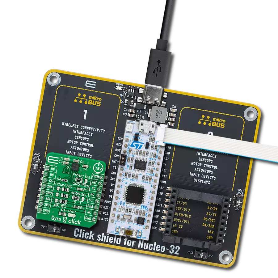
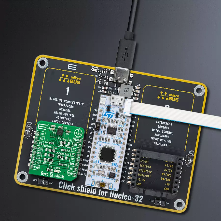
Click Shield for Nucleo-32 is the perfect way to expand your development board's functionalities with STM32 Nucleo-32 pinout. The Click Shield for Nucleo-32 provides two mikroBUS™ sockets to add any functionality from our ever-growing range of Click boards™. We are fully stocked with everything, from sensors and WiFi transceivers to motor control and audio amplifiers. The Click Shield for Nucleo-32 is compatible with the STM32 Nucleo-32 board, providing an affordable and flexible way for users to try out new ideas and quickly create prototypes with any STM32 microcontrollers, choosing from the various combinations of performance, power consumption, and features. The STM32 Nucleo-32 boards do not require any separate probe as they integrate the ST-LINK/V2-1 debugger/programmer and come with the STM32 comprehensive software HAL library and various packaged software examples. This development platform provides users with an effortless and common way to combine the STM32 Nucleo-32 footprint compatible board with their favorite Click boards™ in their upcoming projects.

Used MCU Pins
mikroBUS™ mapper
Take a closer look
Click board™ Schematic

Step by step
Project assembly

Start by selecting your development board and Click board™. Begin with the Nucleo 32 with STM32L432KC MCU as your development board.


Track your results in real time
Application Output
1. Application Output - In Debug mode, the 'Application Output' window enables real-time data monitoring, offering direct insight into execution results. Ensure proper data display by configuring the environment correctly using the provided tutorial.

2. UART Terminal - Use the UART Terminal to monitor data transmission via a USB to UART converter, allowing direct communication between the Click board™ and your development system. Configure the baud rate and other serial settings according to your project's requirements to ensure proper functionality. For step-by-step setup instructions, refer to the provided tutorial.

3. Plot Output - The Plot feature offers a powerful way to visualize real-time sensor data, enabling trend analysis, debugging, and comparison of multiple data points. To set it up correctly, follow the provided tutorial, which includes a step-by-step example of using the Plot feature to display Click board™ readings. To use the Plot feature in your code, use the function: plot(*insert_graph_name*, variable_name);. This is a general format, and it is up to the user to replace 'insert_graph_name' with the actual graph name and 'variable_name' with the parameter to be displayed.

Software Support
Library Description
This library contains API for Gyro 6 Click driver.
Key functions:
gyro6_get_axis- This function reads the gyroscope values for all three axisgyro6_read_die_temperature- This function reads the chip internal temperaturegyro6_set_low_power_mode- This function enables low power mode and sets the sample rate and average sample data
Open Source
Code example
The complete application code and a ready-to-use project are available through the NECTO Studio Package Manager for direct installation in the NECTO Studio. The application code can also be found on the MIKROE GitHub account.
/*!
 * @file main.c
 * @brief Gyro6 Click example
 *
 * # Description
 * This example demonstrates the use of Gyro 6 Click board.
 *
 * The demo application is composed of two sections :
 *
 * ## Application Init
 * Initializes the driver and performs the Click default configuration.
 *
 * ## Application Task
 * Waits for the data to be ready, then reads the values of all three axis
 * and displays the results on the USB UART. The data sample rate is set to 10Hz by default,
 * therefore the data is being read approximately every 100ms.
 *
 * @author Stefan Filipovic
 *
 */

#include "board.h"
#include "log.h"
#include "gyro6.h"

static gyro6_t gyro6;
static log_t logger;

void application_init ( void )
{
    log_cfg_t log_cfg;      /**< Logger config object. */
    gyro6_cfg_t gyro6_cfg;  /**< Click config object. */

    /**
     * Logger initialization.
     * Default baud rate: 115200
     * Default log level: LOG_LEVEL_DEBUG
     * @note If USB_UART_RX and USB_UART_TX
     * are defined as HAL_PIN_NC, you will
     * need to define them manually for log to work.
     * See @b LOG_MAP_USB_UART macro definition for detailed explanation.
     */
    LOG_MAP_USB_UART( log_cfg );
    log_init( &logger, &log_cfg );
    log_info( &logger, " Application Init " );

    // Click initialization.
    gyro6_cfg_setup( &gyro6_cfg );
    GYRO6_MAP_MIKROBUS( gyro6_cfg, MIKROBUS_1 );
    err_t init_flag  = gyro6_init( &gyro6, &gyro6_cfg );
    if ( ( I2C_MASTER_ERROR == init_flag ) || ( SPI_MASTER_ERROR == init_flag ) )
    {
        log_error( &logger, " Application Init Error. " );
        log_info( &logger, " Please, run program again... " );
        for ( ; ; );
    }

    if ( GYRO6_ERROR == gyro6_default_cfg ( &gyro6 ) )
    {
        log_error( &logger, " Default Config Error. " );
        log_info( &logger, " Please, run program again... " );
        for ( ; ; );
    }

    log_info( &logger, " Application Task " );
}

void application_task ( void )
{
    if ( gyro6_get_int_pin ( &gyro6 ) )
    {
        float x_axis_value = 0;
        float y_axis_value = 0;
        float z_axis_value = 0;

        if ( GYRO6_OK == gyro6_get_axis ( &gyro6, &x_axis_value, &y_axis_value, &z_axis_value ) )
        {
            log_printf( &logger, " X : %.2f\r\n", x_axis_value );
            log_printf( &logger, " Y : %.2f\r\n", y_axis_value );
            log_printf( &logger, " Z : %.2f\r\n\n", z_axis_value );
        }
    }
}

int main ( void )
{
    /* Do not remove this line or clock might not be set correctly. */
    #ifdef PREINIT_SUPPORTED
    preinit();
    #endif

    application_init( );

    for ( ; ; )
    {
        application_task( );
    }

    return 0;
}

// ------------------------------------------------------------------------ END


