Gain a clear view of AC or DC current profiles using TMCS1108A2U and STM32F031K6
Efficiency amplified through advanced current sensing

Published Oct 01, 2024
Click board™
Hall Current 11 Click
Dev. board
Nucleo 32 with STM32F031K6 MCU
Compiler
NECTO Studio
MCU
STM32F031K6
Elevate your engineering projects with our Hall-effect current sensing solution, delivering accurate and actionable current data for effective system design, optimization, and maintenance
A
A
Hardware Overview
How does it work?
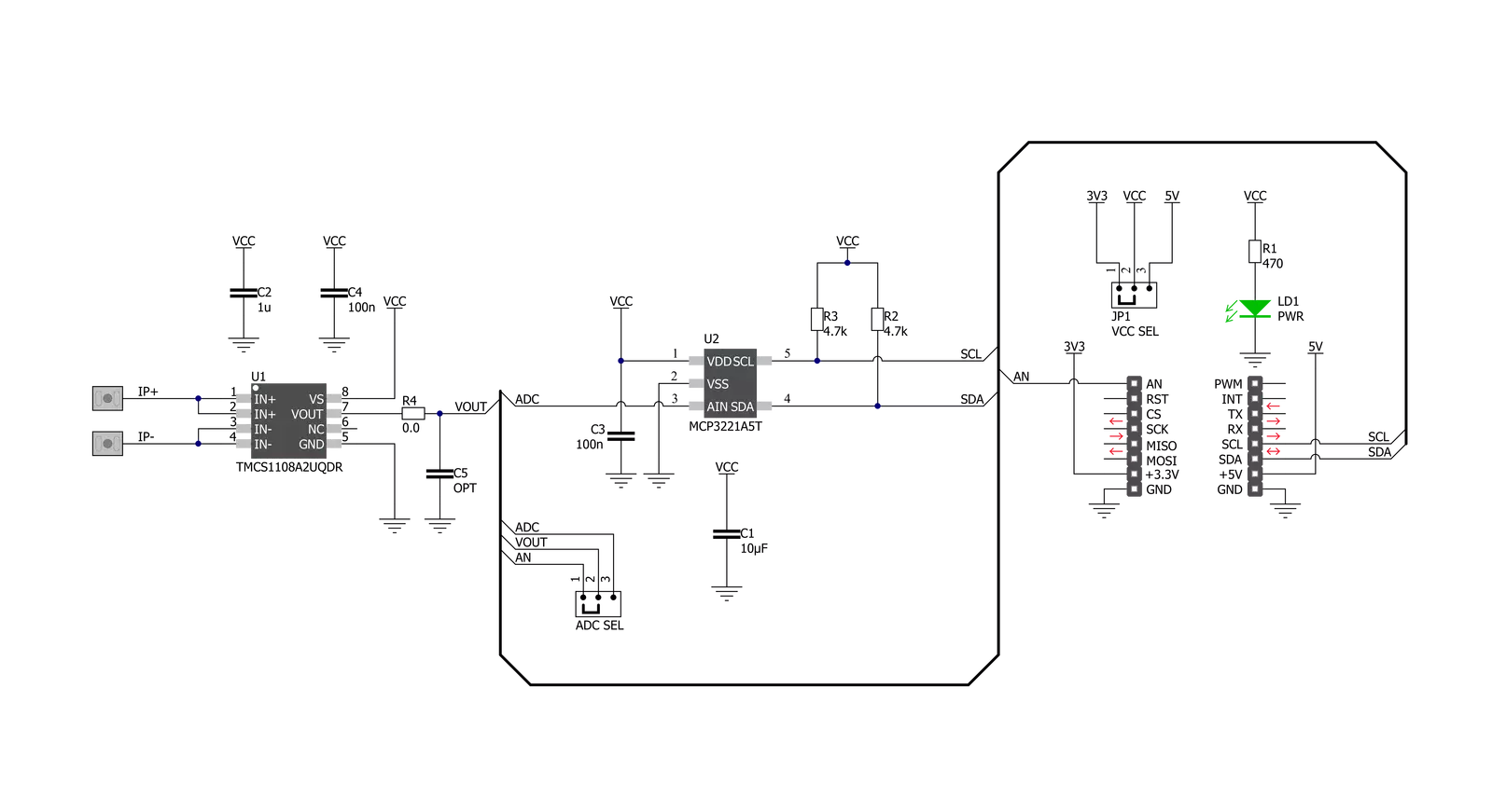
Hall Current 11 Click is based on the TMCS1108A2U, a precision Hall-effect current sensor featuring a 100V functional isolation working voltage, <3% full-scale error across temperature, and both unidirectional and bidirectional current sensing from Texas Instruments. The input current flows through a 1.8mΩ resistance conductor between the isolated input current pins, minimizing power loss and thermal dissipation. The magnetic field generated by the input current is sensed by a Hall sensor and amplified by a precision integrated signal chain. The TMCS1108A2U can be used for both AC and DC current measurements with a bandwidth of 80kHz. The TMCS1108A2U is optimized for high accuracy and temperature stability, with both offset and sensitivity compensated across the entire operating
temperature range. Based on the selected logic voltage VCC, the TMCS1108A2U allows the user to measure current in two appropriate ranges, where after that, can process the output signal in analog or digital form. With the selected logic voltage of 3.3V, it is possible to measure the current from -2.8A to 27.7A, while with the chosen 5V, it is possible to measure it in the range from -4.5A to 43A. The analog output signal of the TMCS1108A2U can be converted to a digital value using MCP3221, a successive approximation A/D converter with a 12-bit resolution from Microchip using a 2-wire I2C compatible interface, or can be sent directly to an analog pin of the mikroBUS™ socket labeled as AN. Selection can be performed by onboard SMD jumper labeled ADC SEL to an appropriate position marked as AN and I2C.
The MCP3221 provides one single-ended input with low power consumption, a low maximum conversion current, and a Standby current of 250μA and 1μA, respectively. Data can be transferred at up to 100kbit/s in the Standard and 400kbit/s in the Fast Mode. Also, maximum sample rates of 22.3kSPS with the MCP3221 are possible in a Continuous-Conversion Mode with a clock rate of 400kHz. This Click board™ can operate with either 3.3V or 5V logic voltage levels selected via the VCC SEL jumper. This way, both 3.3V and 5V capable MCUs can use the communication lines properly. Also, this Click board™ comes equipped with a library containing easy-to-use functions and an example code that can be used, as a reference, for further development.


Features overview
Development board
Nucleo 32 with STM32F031K6 MCU board provides an affordable and flexible platform for experimenting with STM32 microcontrollers in 32-pin packages. Featuring Arduino™ Nano connectivity, it allows easy expansion with specialized shields, while being mbed-enabled for seamless integration with online resources. The
board includes an on-board ST-LINK/V2-1 debugger/programmer, supporting USB reenumeration with three interfaces: Virtual Com port, mass storage, and debug port. It offers a flexible power supply through either USB VBUS or an external source. Additionally, it includes three LEDs (LD1 for USB communication, LD2 for power,
and LD3 as a user LED) and a reset push button. The STM32 Nucleo-32 board is supported by various Integrated Development Environments (IDEs) such as IAR™, Keil®, and GCC-based IDEs like AC6 SW4STM32, making it a versatile tool for developers.

Microcontroller Overview
MCU Card / MCU

Architecture
ARM Cortex-M0
MCU Memory (KB)
32
Silicon Vendor
STMicroelectronics
Pin count
32
RAM (Bytes)
4096
You complete me!
Accessories
Click Shield for Nucleo-32 is the perfect way to expand your development board's functionalities with STM32 Nucleo-32 pinout. The Click Shield for Nucleo-32 provides two mikroBUS™ sockets to add any functionality from our ever-growing range of Click boards™. We are fully stocked with everything, from sensors and WiFi transceivers to motor control and audio amplifiers. The Click Shield for Nucleo-32 is compatible with the STM32 Nucleo-32 board, providing an affordable and flexible way for users to try out new ideas and quickly create prototypes with any STM32 microcontrollers, choosing from the various combinations of performance, power consumption, and features. The STM32 Nucleo-32 boards do not require any separate probe as they integrate the ST-LINK/V2-1 debugger/programmer and come with the STM32 comprehensive software HAL library and various packaged software examples. This development platform provides users with an effortless and common way to combine the STM32 Nucleo-32 footprint compatible board with their favorite Click boards™ in their upcoming projects.

Used MCU Pins
mikroBUS™ mapper
Take a closer look
Click board™ Schematic
Step by step
Project assembly

Start by selecting your development board and Click board™. Begin with the Nucleo 32 with STM32F031K6 MCU as your development board.


Track your results in real time
Application Output
1. Application Output - In Debug mode, the 'Application Output' window enables real-time data monitoring, offering direct insight into execution results. Ensure proper data display by configuring the environment correctly using the provided tutorial.

2. UART Terminal - Use the UART Terminal to monitor data transmission via a USB to UART converter, allowing direct communication between the Click board™ and your development system. Configure the baud rate and other serial settings according to your project's requirements to ensure proper functionality. For step-by-step setup instructions, refer to the provided tutorial.

3. Plot Output - The Plot feature offers a powerful way to visualize real-time sensor data, enabling trend analysis, debugging, and comparison of multiple data points. To set it up correctly, follow the provided tutorial, which includes a step-by-step example of using the Plot feature to display Click board™ readings. To use the Plot feature in your code, use the function: plot(*insert_graph_name*, variable_name);. This is a general format, and it is up to the user to replace 'insert_graph_name' with the actual graph name and 'variable_name' with the parameter to be displayed.

Software Support
Library Description
This library contains API for Hall Current 11 Click driver.
Key functions:
hallcurrent11_get_adc- Hall Current 11 ADC reading functionhallcurrent11_get_adc_voltage- Hall Current 11 get ADC voltage functionhallcurrent11_get_current- Hall Current 11 get current function
Open Source
Code example
The complete application code and a ready-to-use project are available through the NECTO Studio Package Manager for direct installation in the NECTO Studio. The application code can also be found on the MIKROE GitHub account.
/*!
* @file main.c
* @brief HallCurrent11 Click example
*
* # Description
* This library contains API for Hall Current 11 Click driver.
* The demo application reads ADC value and current ( A ).
*
* The demo application is composed of two sections :
*
* ## Application Init
* Initializes I2C driver and log UART.
* After driver initialization the app set default settings.
*
* ## Application Task
* This is an example that demonstrates the use of the Hall Current 11 Click board™.
* In this example, we read and display the ADC values and current ( A ) data.
* Results are being sent to the Usart Terminal where you can track their changes.
*
* @author Nenad Filipovic
*
*/
#include "board.h"
#include "log.h"
#include "hallcurrent11.h"
static hallcurrent11_t hallcurrent11;
static log_t logger;
void application_init ( void )
{
log_cfg_t log_cfg; /**< Logger config object. */
hallcurrent11_cfg_t hallcurrent11_cfg; /**< Click config object. */
/**
* Logger initialization.
* Default baud rate: 115200
* Default log level: LOG_LEVEL_DEBUG
* @note If USB_UART_RX and USB_UART_TX
* are defined as HAL_PIN_NC, you will
* need to define them manually for log to work.
* See @b LOG_MAP_USB_UART macro definition for detailed explanation.
*/
LOG_MAP_USB_UART( log_cfg );
log_init( &logger, &log_cfg );
log_info( &logger, " Application Init " );
// Click initialization.
hallcurrent11_cfg_setup( &hallcurrent11_cfg );
HALLCURRENT11_MAP_MIKROBUS( hallcurrent11_cfg, MIKROBUS_1 );
err_t init_flag = hallcurrent11_init( &hallcurrent11, &hallcurrent11_cfg );
if ( I2C_MASTER_ERROR == init_flag )
{
log_error( &logger, " Application Init Error. " );
log_info( &logger, " Please, run program again... " );
for ( ; ; );
}
hallcurrent11_default_cfg ( &hallcurrent11 );
log_info( &logger, " Application Task " );
log_printf( &logger, "--------------------------\r\n" );
Delay_ms ( 100 );
}
void application_task ( void )
{
static uint16_t adc_data;
static float current;
hallcurrent11_get_adc( &hallcurrent11, &adc_data );
log_printf( &logger, " ADC Value : %d \r\n", adc_data );
log_printf( &logger, "- - - - - - - - - - - - -\r\n" );
Delay_ms ( 100 );
hallcurrent11_get_current ( &hallcurrent11, ¤t );
log_printf( &logger, " Current : %.3f A \r\n", current );
log_printf( &logger, "--------------------------\r\n" );
Delay_ms ( 1000 );
}
int main ( void )
{
/* Do not remove this line or clock might not be set correctly. */
#ifdef PREINIT_SUPPORTED
preinit();
#endif
application_init( );
for ( ; ; )
{
application_task( );
}
return 0;
}
// ------------------------------------------------------------------------ END
Additional Support
Resources
Category:Current sensor


