Monitor your heart's activity with MAX30100 and STM32F031K6
Track your heart's every beat

Published Oct 01, 2024
Click board™
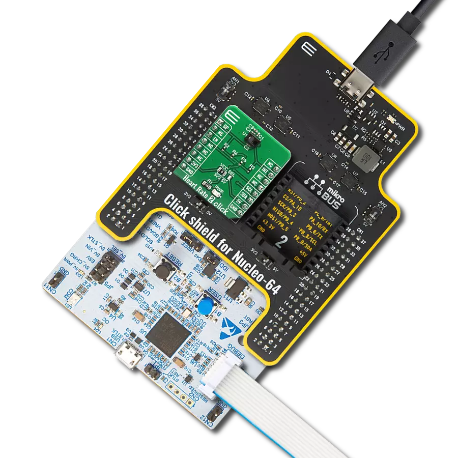
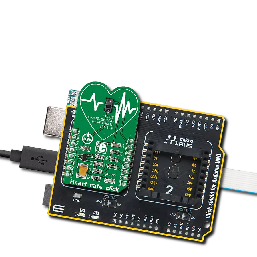
Heart rate Click
Dev. board
Nucleo 32 with STM32F031K6 MCU
Compiler
NECTO Studio
MCU
STM32F031K6
Deliver dependable and precise monitoring that empowers you to make informed decisions regarding your health and well-being
A
A
Hardware Overview
How does it work?
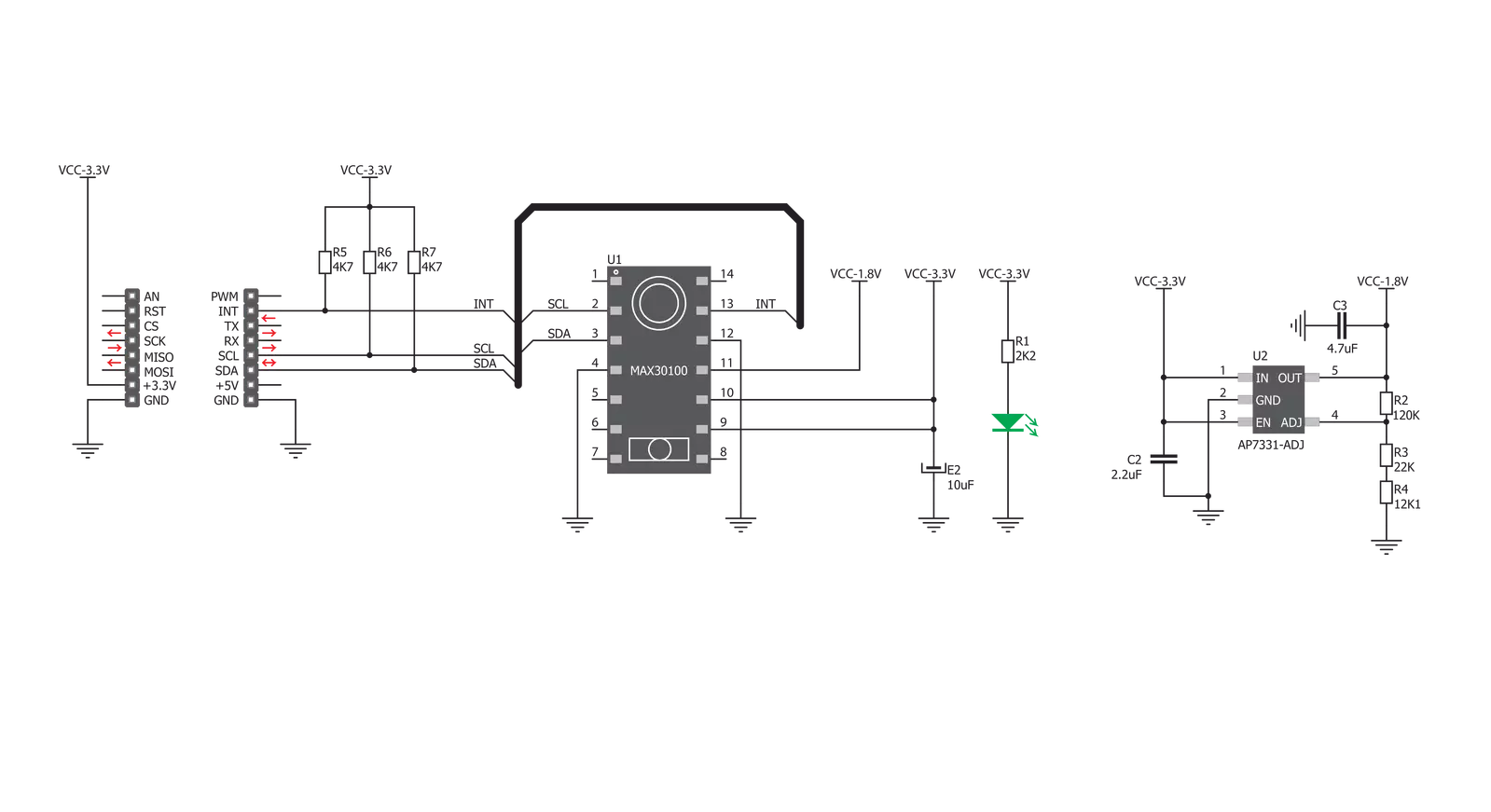
Heart Rate Click is based on the MAX30100, a pulse oximeter, and a heart rate sensor from Analog Devices. This sensor features two integrated LEDs, the RED and IR LEDs. The reflected light is detected by a red/IR photo-detector element and sampled by a low noise delta-sigma 16bit ADC. The analog front end of the MAX30100 sensor features an Ambient Light Cancellation (ALC) section, which eliminates light pollution of the photo-detector element. A discrete-time filter filters
the 16-bit ADC to prevent 50/60Hz interference and hum. The output sampling frequency can be adjusted from 50Hz to 1kHz. There is also a temperature sensor, which can compensate for the environmental changes and calibrate the measurements. Heart Rate Click uses a standard 2-Wire I2C interface to communicate with the host MCU. The interrupt over the INT pin can be generated from five different sources: power ready, SpO2 ready, HR read, temp ready, and FIFO full.
The MAX30100 sensor has the FIFO buffer, which is 16 words deep. This Click board™ can be operated only with a 3.3V logic voltage level. The board must perform appropriate logic voltage level conversion before using MCUs with different logic levels. Also, this Click board™ comes equipped with a library containing easy-to-use functions and an example code that can be used as a reference for further development.

Features overview
Development board
Nucleo 32 with STM32F031K6 MCU board provides an affordable and flexible platform for experimenting with STM32 microcontrollers in 32-pin packages. Featuring Arduino™ Nano connectivity, it allows easy expansion with specialized shields, while being mbed-enabled for seamless integration with online resources. The
board includes an on-board ST-LINK/V2-1 debugger/programmer, supporting USB reenumeration with three interfaces: Virtual Com port, mass storage, and debug port. It offers a flexible power supply through either USB VBUS or an external source. Additionally, it includes three LEDs (LD1 for USB communication, LD2 for power,
and LD3 as a user LED) and a reset push button. The STM32 Nucleo-32 board is supported by various Integrated Development Environments (IDEs) such as IAR™, Keil®, and GCC-based IDEs like AC6 SW4STM32, making it a versatile tool for developers.

Microcontroller Overview
MCU Card / MCU

Architecture
ARM Cortex-M0
MCU Memory (KB)
32
Silicon Vendor
STMicroelectronics
Pin count
32
RAM (Bytes)
4096
You complete me!
Accessories
Click Shield for Nucleo-32 is the perfect way to expand your development board's functionalities with STM32 Nucleo-32 pinout. The Click Shield for Nucleo-32 provides two mikroBUS™ sockets to add any functionality from our ever-growing range of Click boards™. We are fully stocked with everything, from sensors and WiFi transceivers to motor control and audio amplifiers. The Click Shield for Nucleo-32 is compatible with the STM32 Nucleo-32 board, providing an affordable and flexible way for users to try out new ideas and quickly create prototypes with any STM32 microcontrollers, choosing from the various combinations of performance, power consumption, and features. The STM32 Nucleo-32 boards do not require any separate probe as they integrate the ST-LINK/V2-1 debugger/programmer and come with the STM32 comprehensive software HAL library and various packaged software examples. This development platform provides users with an effortless and common way to combine the STM32 Nucleo-32 footprint compatible board with their favorite Click boards™ in their upcoming projects.

Used MCU Pins
mikroBUS™ mapper
Take a closer look
Click board™ Schematic
Step by step
Project assembly

Start by selecting your development board and Click board™. Begin with the Nucleo 32 with STM32F031K6 MCU as your development board.


Track your results in real time
Application Output
1. Application Output - In Debug mode, the 'Application Output' window enables real-time data monitoring, offering direct insight into execution results. Ensure proper data display by configuring the environment correctly using the provided tutorial.

2. UART Terminal - Use the UART Terminal to monitor data transmission via a USB to UART converter, allowing direct communication between the Click board™ and your development system. Configure the baud rate and other serial settings according to your project's requirements to ensure proper functionality. For step-by-step setup instructions, refer to the provided tutorial.

3. Plot Output - The Plot feature offers a powerful way to visualize real-time sensor data, enabling trend analysis, debugging, and comparison of multiple data points. To set it up correctly, follow the provided tutorial, which includes a step-by-step example of using the Plot feature to display Click board™ readings. To use the Plot feature in your code, use the function: plot(*insert_graph_name*, variable_name);. This is a general format, and it is up to the user to replace 'insert_graph_name' with the actual graph name and 'variable_name' with the parameter to be displayed.

Software Support
Library Description
This library contains API for Heart rate Click driver.
Key functions:
heartrate_data_ready- Using this function we can check if the data is ready for readingheartrate_read_ir_red- Using this function we can read IR and RED valuesheartrate_generic_read- This function reads data from the desired register
Open Source
Code example
The complete application code and a ready-to-use project are available through the NECTO Studio Package Manager for direct installation in the NECTO Studio. The application code can also be found on the MIKROE GitHub account.
/*!
 * \file
 * \brief HeartRate Click example
 *
 * # Description
 * This Click features an advanced oximeter and heart rate monitoring sensor,
 * which relies on two integrated LEDs. It is enough to place an index finger on a top
 * of the sensor to get both of the heart rate and blood oxygen saturation via the I2C interface.
 *
 * The demo application is composed of two sections :
 *
 * ## Application Init
 * Initializes heartrate driver and set the Click board default configuration.
 *
 * ## Application Task
 * Reading values from both Ir and Red diode and displaying their average values on the USB UART.
 *
 * \author MikroE Team
 *
 */
// ------------------------------------------------------------------- INCLUDES

#include "board.h"
#include "log.h"
#include "heartrate.h"

// ------------------------------------------------------------------ VARIABLES

static heartrate_t heartrate;
static log_t logger;

static uint16_t  counter = 500;
static uint8_t  sample_num;

static uint16_t ir_buff[ 16 ]  = { 0 };
static uint16_t red_buff[ 16 ] = { 0 };
static uint32_t ir_average;
static uint32_t red_average;

// ------------------------------------------------------ APPLICATION FUNCTIONS

void application_init ( void )
{
    log_cfg_t log_cfg;
    heartrate_cfg_t cfg;

    /**
     * Logger initialization.
     * Default baud rate: 115200
     * Default log level: LOG_LEVEL_DEBUG
     * @note If USB_UART_RX and USB_UART_TX
     * are defined as HAL_PIN_NC, you will
     * need to define them manually for log to work.
     * See @b LOG_MAP_USB_UART macro definition for detailed explanation.
     */
    LOG_MAP_USB_UART( log_cfg );
    log_init( &logger, &log_cfg );
    log_info( &logger, "---- Application Init ----" );

    //  Click initialization.

    heartrate_cfg_setup( &cfg );
    HEARTRATE_MAP_MIKROBUS( cfg, MIKROBUS_1 );
    heartrate_init( &heartrate, &cfg );

    heartrate_default_cfg( &heartrate );
    Delay_ms ( 100 );
}

void application_task ( void )
{
    if ( heartrate_data_ready( &heartrate ) )
    {
        sample_num = heartrate_read_ir_red( &heartrate, ir_buff, red_buff );
        if ( sample_num > 0 )
        {
            ir_average = 0;
            red_average = 0;
            for ( uint8_t cnt = 0; cnt < sample_num; cnt++ )
            {
                ir_average += ir_buff[ cnt ];
                red_average += red_buff[ cnt ];
            }
            ir_average  /= sample_num;
            red_average /= sample_num;
            counter++;
            if( red_average > 100 && ir_average > 100 )
            {
                log_printf( &logger, "%lu;%lu;\r\n", red_average, ir_average );
                counter = 500;
            }
            else
            {
                if ( counter > 500 )
                {
                    log_printf( &logger, "Please place your index finger on the sensor.\r\n" );
                    counter = 0;
                }
            }
        }
    }
}

int main ( void )
{
    /* Do not remove this line or clock might not be set correctly. */
    #ifdef PREINIT_SUPPORTED
    preinit();
    #endif

    application_init( );

    for ( ; ; )
    {
        application_task( );
    }

    return 0;
}


// ------------------------------------------------------------------------ END