Track your blood oxygen levels with ADPD144RI and STM32F031K6
Your digitally-supported wellness journey

Published Oct 01, 2024
Click board™
Oximeter 2 Click
Dev. board
Nucleo 32 with STM32F031K6 MCU
Compiler
NECTO Studio
MCU
STM32F031K6
Enhance your solution by incorporating an advanced health monitoring feature that offers real-time heart rate and blood oxygen saturation data
A
A
Hardware Overview
How does it work?
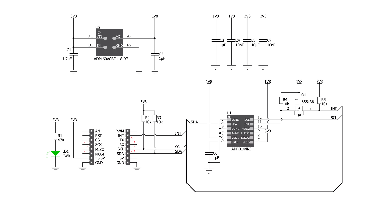
Oximeter 2 Click is based on the ADPD144RI, a highly integrated, photometric front end optimized for photoplethysmography (PPG) detection of blood oxygenation from Analog Devices. It combines highly efficient red and infrared LED emitters, with 660nm red and 880nm IR wavelengths, and a sensitive 4-channel photodiode with a custom ASIC that provides optical isolation between the integrated LED emitters and the detection photodiodes to improve the signal-to-noise ratio. It uses synchronous detection of optical pulses to enhance the rejection of ambient light in addition to low power consumption. The Oximeter 2 Click is designed for ultralow direct optical reflections, with independent AFE settings per channel and I2C control interface. The integrated LED emitters produce light
pulses in sync with the active sampling period of the AFE, which consists of a programmable TIA, a band-pass filter, and an integrator. The processed analog signals are digitized by a 14-bit ADC and summed by the 20-bit burst accumulator. Four simultaneous sampling channels are matrixed into two independent time slots (one for each LED wavelength). An adjustable number of pulses per sample, accumulation, and averaging can be applied to multiple samples to increase the dynamic range to 27 bits. Oximeter 2 Click communicates with MCU using the standard I2C 2-Wire interface, with a typical clock frequency of 400kHz. A high-speed I2C interface reads data from output registers directly or through a FIFO buffer. All register writes are single words only and
require 16 bits of data. It also comes with a programmable interrupt line, labeled as INT and routed on the INT pin of the mikroBUS™ socket that simplifies timely data access. The ADPD144RI does not require a specific Power-Up sequence but requires a supply voltage of 1.8V to work properly. Therefore, a small regulating LDO, the ADP160 from Analog Devices, provides a 1.8V out of 3.3V mikroBUS™ rail. This Click board™ can only be operated with a 3.3V logic voltage level. The board must perform appropriate logic voltage level conversion before using MCUs with different logic levels. However, the Click board™ comes equipped with a library containing functions and an example code that can be used as a reference for further development.


Features overview
Development board
Nucleo 32 with STM32F031K6 MCU board provides an affordable and flexible platform for experimenting with STM32 microcontrollers in 32-pin packages. Featuring Arduino™ Nano connectivity, it allows easy expansion with specialized shields, while being mbed-enabled for seamless integration with online resources. The
board includes an on-board ST-LINK/V2-1 debugger/programmer, supporting USB reenumeration with three interfaces: Virtual Com port, mass storage, and debug port. It offers a flexible power supply through either USB VBUS or an external source. Additionally, it includes three LEDs (LD1 for USB communication, LD2 for power,
and LD3 as a user LED) and a reset push button. The STM32 Nucleo-32 board is supported by various Integrated Development Environments (IDEs) such as IAR™, Keil®, and GCC-based IDEs like AC6 SW4STM32, making it a versatile tool for developers.

Microcontroller Overview
MCU Card / MCU

Architecture
ARM Cortex-M0
MCU Memory (KB)
32
Silicon Vendor
STMicroelectronics
Pin count
32
RAM (Bytes)
4096
You complete me!
Accessories
Click Shield for Nucleo-32 is the perfect way to expand your development board's functionalities with STM32 Nucleo-32 pinout. The Click Shield for Nucleo-32 provides two mikroBUS™ sockets to add any functionality from our ever-growing range of Click boards™. We are fully stocked with everything, from sensors and WiFi transceivers to motor control and audio amplifiers. The Click Shield for Nucleo-32 is compatible with the STM32 Nucleo-32 board, providing an affordable and flexible way for users to try out new ideas and quickly create prototypes with any STM32 microcontrollers, choosing from the various combinations of performance, power consumption, and features. The STM32 Nucleo-32 boards do not require any separate probe as they integrate the ST-LINK/V2-1 debugger/programmer and come with the STM32 comprehensive software HAL library and various packaged software examples. This development platform provides users with an effortless and common way to combine the STM32 Nucleo-32 footprint compatible board with their favorite Click boards™ in their upcoming projects.

Used MCU Pins
mikroBUS™ mapper
Take a closer look
Click board™ Schematic
Step by step
Project assembly

Start by selecting your development board and Click board™. Begin with the Nucleo 32 with STM32F031K6 MCU as your development board.


Track your results in real time
Application Output
1. Application Output - In Debug mode, the 'Application Output' window enables real-time data monitoring, offering direct insight into execution results. Ensure proper data display by configuring the environment correctly using the provided tutorial.

2. UART Terminal - Use the UART Terminal to monitor data transmission via a USB to UART converter, allowing direct communication between the Click board™ and your development system. Configure the baud rate and other serial settings according to your project's requirements to ensure proper functionality. For step-by-step setup instructions, refer to the provided tutorial.

3. Plot Output - The Plot feature offers a powerful way to visualize real-time sensor data, enabling trend analysis, debugging, and comparison of multiple data points. To set it up correctly, follow the provided tutorial, which includes a step-by-step example of using the Plot feature to display Click board™ readings. To use the Plot feature in your code, use the function: plot(*insert_graph_name*, variable_name);. This is a general format, and it is up to the user to replace 'insert_graph_name' with the actual graph name and 'variable_name' with the parameter to be displayed.

Software Support
Library Description
This library contains API for Oximeter 2 Click driver.
Key functions:
void oximeter2_cfg_setup ( oximeter2_cfg_t *cfg );- Config Object Initialization function.OXIMETER2_RETVAL oximeter2_init ( oximeter2_t *ctx, oximeter2_cfg_t *cfg );- Initialization function.
Open Source
Code example
The complete application code and a ready-to-use project are available through the NECTO Studio Package Manager for direct installation in the NECTO Studio. The application code can also be found on the MIKROE GitHub account.
/*!
 * \file main.c
 * \brief Oximeter2 Click example
 *
 * # Description
 * This application collects data from the sensor, calculates it and then logs
 * the result.
 *
 * The demo application is composed of two sections :
 *
 * ## Application Init
 * Initializes driver and performs the device configuration which puts Time Slot A
 * and Time Slot B modes to active state.
 * Before the device configuration, the SW reset will be performed, which puts
 * the registers in their initial state.
 *
 * ## Application Task
 * Application measures value of oxygen level in human's blood.
 *
 *
 * \author MikroE Team
 *
 */
// ------------------------------------------------------------------- INCLUDES

#include "board.h"
#include "log.h"
#include "oximeter2.h"

// ------------------------------------------------------------------ VARIABLES

// Oximeter 2 context instance declaration.
static oximeter2_t oximeter2;

// Logger context instance declaration.
static log_t logger;

// Result storage.
static uint32_t res_slot[ 100 ];

// ------------------------------------------------------ APPLICATION FUNCTIONS

void oximeter2_write_res ( uint32_t data_write )
{
    log_printf( &logger, "%u\r\n", data_write );
}

void oximeter2_logs_results( void )
{
    uint8_t final_result;

    oximeter2_read_data( &oximeter2, &res_slot[ 0 ] );

    log_printf( &logger, "Average result per photodiode is: \r\n" );

    switch ( oximeter2.enabled_channel )
    {
        case OXIMETER2_CH3_CH4_SELECTED:
        {
            log_printf( &logger, "PD3: " );
            oximeter2_write_res( res_slot[ 2 ] );
            log_printf( &logger, "PD4: " );
            oximeter2_write_res( res_slot[ 3 ] );

            final_result = ( res_slot[ 2 ] + res_slot[ 3 ] ) / 1000;
            break;
        }
        case OXIMETER2_ALL_CHANNELS_SELECTED:
        {
            log_printf( &logger, "PD1: " );
            oximeter2_write_res( res_slot[ 0 ] );
            log_printf( &logger, "PD2: " );
            oximeter2_write_res( res_slot[ 1 ] );
            log_printf( &logger, "PD3: " );
            oximeter2_write_res( res_slot[ 2 ] );
            log_printf( &logger, "PD4: " );
            oximeter2_write_res( res_slot[ 3 ]);

            final_result = ( res_slot[ 0 ] + res_slot [ 1 ] + res_slot[ 2 ] + res_slot[ 3 ] ) / 1000;
            break;
        }
        default:
        {
            break;
        }
    }

    if (final_result > 100)
    {
        final_result = 100;
    }
    log_printf( &logger, "Average result, in percentage: %u\r\n", ( uint16_t )final_result );
    log_printf( &logger, "-------------------------\r\n" );

    Delay_ms ( 300 );
}

void application_init ( void )
{
    log_cfg_t log_cfg;
    oximeter2_cfg_t cfg;

    /**
     * Logger initialization.
     * Default baud rate: 115200
     * Default log level: LOG_LEVEL_DEBUG
     * @note If USB_UART_RX and USB_UART_TX
     * are defined as HAL_PIN_NC, you will
     * need to define them manually for log to work.
     * See @b LOG_MAP_USB_UART macro definition for detailed explanation.
     */
    LOG_MAP_USB_UART( log_cfg );
    log_init( &logger, &log_cfg );
    log_info( &logger, "---- Application Init ----" );

    //  Click initialization.
    oximeter2_cfg_setup( &cfg );
    OXIMETER2_MAP_MIKROBUS( cfg, MIKROBUS_1 );
    oximeter2_init( &oximeter2, &cfg );
    oximeter2_default_cfg( &oximeter2 );
}

void application_task ( void )
{
    oximeter2_logs_results();
}

int main ( void )
{
    /* Do not remove this line or clock might not be set correctly. */
    #ifdef PREINIT_SUPPORTED
    preinit();
    #endif

    application_init( );

    for ( ; ; )
    {
        application_task( );
    }

    return 0;
}

// ------------------------------------------------------------------------ END


