Ensure seamless data transmission using ADuM341E and STM32F031K6
SPI Isolator: The key to reliable data transmission

Published Oct 01, 2024
Click board™
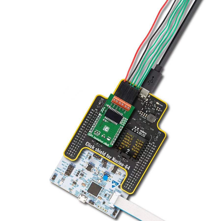
SPI Isolator 4 Click
Dev. board
Nucleo 32 with STM32F031K6 MCU
Compiler
NECTO Studio
MCU
STM32F031K6
This isolator allows you to bridge the gap between systems with different ground references, ensuring that data is transmitted accurately and without disruptions
A
A
Hardware Overview
How does it work?
SPI Isolator 4 Click is based on the ADuM341E, a quad-channel digital isolator optimized for a serial peripheral interface from Analog Devices. This isolation component provides outstanding performance characteristics by combining high-speed and CMOS technology. It uses a high-frequency carrier to transmit data across the isolation barrier using iCoupler chip scale transformer coils separated by layers of polyimide isolation. Its data channels are independent and available in various configurations with a withstand voltage rating of 5kVrms. Using an ON/OFF keying (OOK) technique and the differential architecture, the ADuM341E has a very low propagation delay and high speed. It operates
with the external supply voltage ranging from 2.25V to 5.5V, providing compatibility with lower voltage systems and enabling voltage translation functionality across the isolation barrier. The ADuM341E architecture is designed for high common-mode transient (CMTI) immunity and high immunity to electrical noise and magnetic interference. Unlike other optocoupler alternatives, DC correctness is ensured without input logic transitions. Two different fail-safe options are available, by which the outputs go into a predetermined state when the input power supply is not applied or the inputs are disabled. SPI Isolator 4 Click communicates with an MCU using the SPI serial interface with a maximum data rate
of 100Mbps. This Click board™ also comes with an SDO line enable control pin, labeled as EN1, routed on the PWM pin of the mikroBUS™ socket. When EN1 is in a high logic state, the SDO line is enabled, and when EN1 is in a low logic state, the SDO line is disabled to the high-Z state. This Click board™ can operate with either 3.3V or 5V logic voltage levels selected via the VCC SEL jumper. This way, both 3.3V and 5V capable MCUs can use the communication lines properly. Also, this Click board™ comes equipped with a library containing easy-to-use functions and an example code that can be used as a reference for further development.


Features overview
Development board
Nucleo 32 with STM32F031K6 MCU board provides an affordable and flexible platform for experimenting with STM32 microcontrollers in 32-pin packages. Featuring Arduino™ Nano connectivity, it allows easy expansion with specialized shields, while being mbed-enabled for seamless integration with online resources. The
board includes an on-board ST-LINK/V2-1 debugger/programmer, supporting USB reenumeration with three interfaces: Virtual Com port, mass storage, and debug port. It offers a flexible power supply through either USB VBUS or an external source. Additionally, it includes three LEDs (LD1 for USB communication, LD2 for power,
and LD3 as a user LED) and a reset push button. The STM32 Nucleo-32 board is supported by various Integrated Development Environments (IDEs) such as IAR™, Keil®, and GCC-based IDEs like AC6 SW4STM32, making it a versatile tool for developers.

Microcontroller Overview
MCU Card / MCU

Architecture
ARM Cortex-M0
MCU Memory (KB)
32
Silicon Vendor
STMicroelectronics
Pin count
32
RAM (Bytes)
4096
You complete me!
Accessories
Click Shield for Nucleo-32 is the perfect way to expand your development board's functionalities with STM32 Nucleo-32 pinout. The Click Shield for Nucleo-32 provides two mikroBUS™ sockets to add any functionality from our ever-growing range of Click boards™. We are fully stocked with everything, from sensors and WiFi transceivers to motor control and audio amplifiers. The Click Shield for Nucleo-32 is compatible with the STM32 Nucleo-32 board, providing an affordable and flexible way for users to try out new ideas and quickly create prototypes with any STM32 microcontrollers, choosing from the various combinations of performance, power consumption, and features. The STM32 Nucleo-32 boards do not require any separate probe as they integrate the ST-LINK/V2-1 debugger/programmer and come with the STM32 comprehensive software HAL library and various packaged software examples. This development platform provides users with an effortless and common way to combine the STM32 Nucleo-32 footprint compatible board with their favorite Click boards™ in their upcoming projects.

Used MCU Pins
mikroBUS™ mapper
Take a closer look
Click board™ Schematic

Step by step
Project assembly

Start by selecting your development board and Click board™. Begin with the Nucleo 32 with STM32F031K6 MCU as your development board.


Track your results in real time
Application Output
1. Application Output - In Debug mode, the 'Application Output' window enables real-time data monitoring, offering direct insight into execution results. Ensure proper data display by configuring the environment correctly using the provided tutorial.

2. UART Terminal - Use the UART Terminal to monitor data transmission via a USB to UART converter, allowing direct communication between the Click board™ and your development system. Configure the baud rate and other serial settings according to your project's requirements to ensure proper functionality. For step-by-step setup instructions, refer to the provided tutorial.

3. Plot Output - The Plot feature offers a powerful way to visualize real-time sensor data, enabling trend analysis, debugging, and comparison of multiple data points. To set it up correctly, follow the provided tutorial, which includes a step-by-step example of using the Plot feature to display Click board™ readings. To use the Plot feature in your code, use the function: plot(*insert_graph_name*, variable_name);. This is a general format, and it is up to the user to replace 'insert_graph_name' with the actual graph name and 'variable_name' with the parameter to be displayed.

Software Support
Library Description
This library contains API for SPI Isolator 4 Click driver.
Key functions:
spiisolator4_generic_write- SPI Isolator 4 data writing functionspiisolator4_generic_read- SPI Isolator 4 data reading function
Open Source
Code example
The complete application code and a ready-to-use project are available through the NECTO Studio Package Manager for direct installation in the NECTO Studio. The application code can also be found on the MIKROE GitHub account.
/*!
 * @file main.c
 * @brief SPIIsolator4 Click example
 *
 * # Description
 * This library contains API for the SPI Isolator 4 click driver.
 * This demo application shows an example of an SPI Isolator 4 click wired
 * to the nvSRAM 4 click for reading Device ID.
 *
 * The demo application is composed of two sections :
 *
 * ## Application Init
 * Initialization of SPI module and log UART.
 * After driver initialization, the app sets the default configuration.
 *
 * ## Application Task
 * This is an example that shows the use of an SPI Isolator 4 click board™.
 * Logs Device ID of the nvSRAM 4 click wired to the SPI Isolator 4 board™.
 * Results are being sent to the Usart Terminal where you can track their changes.
 *
 * ## Additional Function
 * - static void get_device_id ( void )
 *
 * @author Mikroe Team
 *
 */

#include "board.h"
#include "log.h"
#include "spiisolator4.h"

static spiisolator4_t spiisolator4;
static log_t logger;
static uint32_t device_id;

static void get_device_id ( void ) {
    uint8_t rx_data[ 4 ];

    spiisolator4_generic_read( &spiisolator4, 0x9F, &rx_data[ 0 ], 4 );

    device_id = rx_data[ 0 ];
    device_id <<= 8;
    device_id |= rx_data[ 1 ];
    device_id <<= 8;
    device_id |= rx_data[ 2 ];
    device_id <<= 8;
    device_id |= rx_data[ 3 ];
}

void application_init ( void )
{
    log_cfg_t log_cfg;                    /**< Logger config object. */
    spiisolator4_cfg_t spiisolator4_cfg;  /**< Click config object. */

    /**
     * Logger initialization.
     * Default baud rate: 115200
     * Default log level: LOG_LEVEL_DEBUG
     * @note If USB_UART_RX and USB_UART_TX
     * are defined as HAL_PIN_NC, you will
     * need to define them manually for log to work.
     * See @b LOG_MAP_USB_UART macro definition for detailed explanation.
     */
    LOG_MAP_USB_UART( log_cfg );
    log_init( &logger, &log_cfg );
    log_info( &logger, " Application Init " );

    // Click initialization.

    spiisolator4_cfg_setup( &spiisolator4_cfg );
    SPIISOLATOR4_MAP_MIKROBUS( spiisolator4_cfg, MIKROBUS_1 );
    err_t init_flag  = spiisolator4_init( &spiisolator4, &spiisolator4_cfg );
    if ( SPI_MASTER_ERROR == init_flag )
    {
        log_error( &logger, " Application Init Error. " );
        log_info( &logger, " Please, run program again... " );

        for ( ; ; );
    }

    spiisolator4_default_cfg ( &spiisolator4 );
    log_info( &logger, " Application Task " );
    log_printf( &logger, "--------------------------\r\n" );
    Delay_ms( 100 );
}

void application_task ( void )
{
    get_device_id( );
    log_printf( &logger, "  Device ID : 0x%.8LX\r\n", device_id );
    log_printf( &logger, "--------------------------\r\n" );
    Delay_ms( 1000 );
}

void main ( void )
{
    application_init( );

    for ( ; ; )
    {
        application_task( );
    }
}

// ------------------------------------------------------------------------ END