Drive a bipolar stepping motor easily with TB67S549FTG and STM32F031K6
Smooth motor drive operation

Published Oct 01, 2024
Click board™
Stepper 12 Click
Dev. board
Nucleo 32 with STM32F031K6 MCU
Compiler
NECTO Studio
MCU
STM32F031K6
Accurate rotation angle and speed control using pulse signals
A
A
Hardware Overview
How does it work?
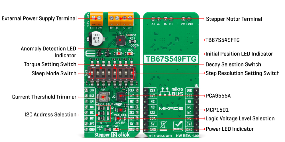
Stepper 12 Click is based on the TB67S549FTG, a two-phase bipolar stepping motor driver designed to control one bipolar stepping motor with resistorless current sensing owing to the built-in function of Advanced Current Detect System (ACDS) from Toshiba Semiconductor. The TB67S549FTG incorporates low on-resistance DMOS FETs, which can deliver a 1.5A maximum current with a motor output voltage rating of 40V and integrated protection mechanisms such as over-current, over-temperature, and under-voltage lockout for error detection (LO LED indicator). It supports full-step to 1/32 steps resolution for less motor noise and smoother control, with a built-in Advanced Dynamic Mixed Decay (ADMD) function that helps stabilize the current waveforms. Thanks to the many steps that TB67S549FTG supports, motor noise can be significantly reduced with smoother operation and more precise control. It is suited to various applications such as office automation and commercial and industrial equipment. The current value in the PWM constant-current mode is set by the reference voltage obtained by the MCP1501, a high-precision voltage regulator. Also, the current threshold point of the TB67S549FTG, alongside MCP1501, can be set manually using an onboard trimmer labeled VR.
In addition to the I2C communication, several GPIO pins connected to the mikroBUS™ socket pins are also used to forward the information to the MCU associated with the PCA9555A port expander. The PCA9555A also allows choosing the least significant bit (LSB) of its I2C slave address by positioning SMD jumpers labeled as ADDR SEL to an appropriate position marked as 0 and 1, alongside its interrupt feature routed to the INT pin of the mikroBUS™ socket. The CLK clock signal, routed to the PWM pin of the mikroBUS™ socket, shifts the current step and electrical angle of the motor with its every up-edge, while the Enable pin, labeled as EN and routed to the CS pin of the mikroBUS™ socket, controls the state of the output A and B stepping motor drive channels. The normal constant current control is started by turning the motor drive ON (HIGH level), while by setting the motor drive OFF, the outputs are turned high impedance because the MOSFETs are set to OFF (LOW level). Besides, all circuits can be stopped using the Sleep function and thus enable power saving mode. A simple DIR pin routed to the AN pin on the mikroBUS™ socket allows MCU to manage the direction of the stepper motor (clockwise or counterclockwise), while the RST pin of the mikroBUS™ socket
initializes an electrical angle in the internal counter to set an initial position. Achieving an initial position is indicated via onboard orange LED labeled as MO. A specific addition to this Click board™ is a multifunctional switch that allows the user, by selecting a particular switch, to set appropriate features such as 1 – Sleep Mode Activation; 2, 3 – Motor Torque Setting; 5 – Decay Control; 6, 7, 8 – Step Resolution Setting. In addition to this physical way of setting these functions, the user can select them digitally via the I2C interface. The Stepper 12 Click supports an external power supply for the TB67S549FTG, which can be connected to the input terminal labeled as VM and should be within the range of 4.5V to 34V, while the stepper motor coils can be connected to the terminals labeled as B+, B-, A-, and A+. This Click board™ can operate with either 3.3V or 5V logic voltage levels selected via the VCC SEL jumper. This way, both 3.3V and 5V capable MCUs can use the communication lines properly. However, the Click board™ comes equipped with a library containing easy-to-use functions and an example code that can be used, as a reference, for further development.
Features overview
Development board
Nucleo 32 with STM32F031K6 MCU board provides an affordable and flexible platform for experimenting with STM32 microcontrollers in 32-pin packages. Featuring Arduino™ Nano connectivity, it allows easy expansion with specialized shields, while being mbed-enabled for seamless integration with online resources. The
board includes an on-board ST-LINK/V2-1 debugger/programmer, supporting USB reenumeration with three interfaces: Virtual Com port, mass storage, and debug port. It offers a flexible power supply through either USB VBUS or an external source. Additionally, it includes three LEDs (LD1 for USB communication, LD2 for power,
and LD3 as a user LED) and a reset push button. The STM32 Nucleo-32 board is supported by various Integrated Development Environments (IDEs) such as IAR™, Keil®, and GCC-based IDEs like AC6 SW4STM32, making it a versatile tool for developers.

Microcontroller Overview
MCU Card / MCU

Architecture
ARM Cortex-M0
MCU Memory (KB)
32
Silicon Vendor
STMicroelectronics
Pin count
32
RAM (Bytes)
4096
You complete me!
Accessories
Click Shield for Nucleo-32 is the perfect way to expand your development board's functionalities with STM32 Nucleo-32 pinout. The Click Shield for Nucleo-32 provides two mikroBUS™ sockets to add any functionality from our ever-growing range of Click boards™. We are fully stocked with everything, from sensors and WiFi transceivers to motor control and audio amplifiers. The Click Shield for Nucleo-32 is compatible with the STM32 Nucleo-32 board, providing an affordable and flexible way for users to try out new ideas and quickly create prototypes with any STM32 microcontrollers, choosing from the various combinations of performance, power consumption, and features. The STM32 Nucleo-32 boards do not require any separate probe as they integrate the ST-LINK/V2-1 debugger/programmer and come with the STM32 comprehensive software HAL library and various packaged software examples. This development platform provides users with an effortless and common way to combine the STM32 Nucleo-32 footprint compatible board with their favorite Click boards™ in their upcoming projects.

The 28BYJ-48 is an adaptable 5VDC stepper motor with a compact design, ideal for various applications. It features four phases, a speed variation ratio of 1/64, and a stride angle of 5.625°/64 steps, allowing precise control. The motor operates at a frequency of 100Hz and has a DC resistance of 50Ω ±7% at 25°C. It boasts an idle in-traction frequency greater than 600Hz and an idle out-traction frequency exceeding 1000Hz, ensuring reliability in different scenarios. With a self-positioning torque and in-traction torque both exceeding 34.3mN.m at 120Hz, the 28BYJ-48 offers robust performance. Its friction torque ranges from 600 to 1200 gf.cm, while the pull-in torque is 300 gf.cm. This motor makes a reliable and efficient choice for your stepper motor needs.

Used MCU Pins
mikroBUS™ mapper
Take a closer look
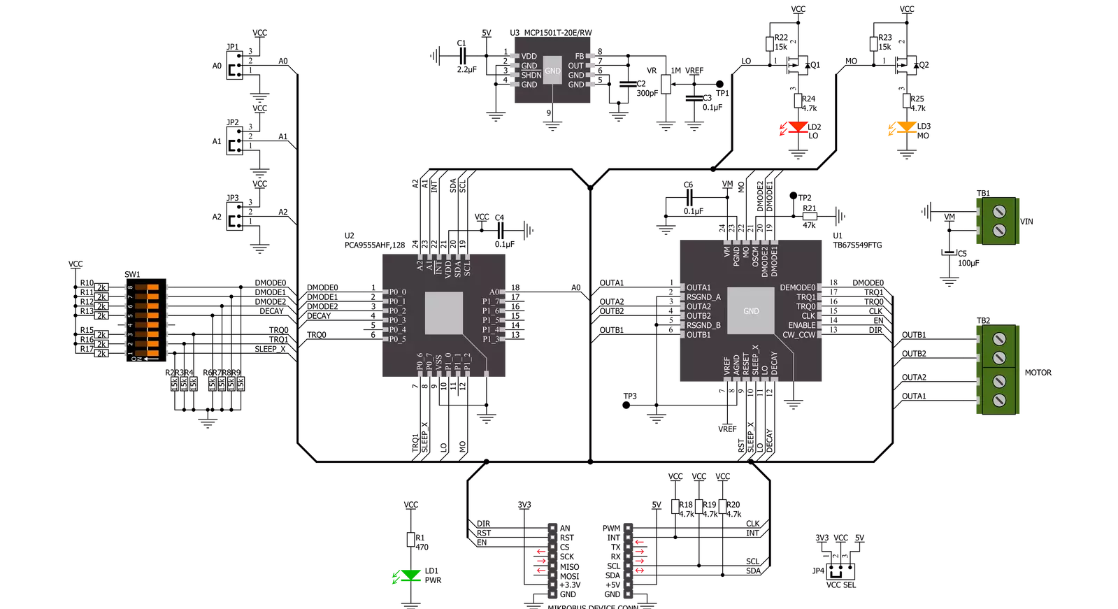
Click board™ Schematic
Step by step
Project assembly

Start by selecting your development board and Click board™. Begin with the Nucleo 32 with STM32F031K6 MCU as your development board.


Track your results in real time
Application Output
1. Application Output - In Debug mode, the 'Application Output' window enables real-time data monitoring, offering direct insight into execution results. Ensure proper data display by configuring the environment correctly using the provided tutorial.

2. UART Terminal - Use the UART Terminal to monitor data transmission via a USB to UART converter, allowing direct communication between the Click board™ and your development system. Configure the baud rate and other serial settings according to your project's requirements to ensure proper functionality. For step-by-step setup instructions, refer to the provided tutorial.

3. Plot Output - The Plot feature offers a powerful way to visualize real-time sensor data, enabling trend analysis, debugging, and comparison of multiple data points. To set it up correctly, follow the provided tutorial, which includes a step-by-step example of using the Plot feature to display Click board™ readings. To use the Plot feature in your code, use the function: plot(*insert_graph_name*, variable_name);. This is a general format, and it is up to the user to replace 'insert_graph_name' with the actual graph name and 'variable_name' with the parameter to be displayed.

Software Support
Library Description
This library contains API for Stepper 12 Click driver.
Key functions:
stepper12_set_directionThis function sets the motor direction by setting the DIR pin logic state.stepper12_drive_motorThis function drives the motor for a specific number of steps at the selected speed.stepper12_set_step_modeThis function sets the step mode resolution settings.
Open Source
Code example
The complete application code and a ready-to-use project are available through the NECTO Studio Package Manager for direct installation in the NECTO Studio. The application code can also be found on the MIKROE GitHub account.
/*!
 * @file main.c
 * @brief Stepper 12 Click example
 *
 * # Description
 * This example demonstrates the use of the Stepper 12 click board by driving the
 * motor in both directions for a desired number of steps.
 *
 * The demo application is composed of two sections :
 *
 * ## Application Init
 * Initializes the driver and performs the click default configuration.
 *
 * ## Application Task
 * Drives the motor clockwise for 200 full steps and then counter-clockiwse for 400 quarter
 * steps with 2 seconds delay before changing the direction. All data is being logged on
 * the USB UART where you can track the program flow.
 *
 * @author Stefan Filipovic
 *
 */

#include "board.h"
#include "log.h"
#include "stepper12.h"

static stepper12_t stepper12;
static log_t logger;

void application_init ( void )
{
    log_cfg_t log_cfg;  /**< Logger config object. */
    stepper12_cfg_t stepper12_cfg;  /**< Click config object. */

    /**
     * Logger initialization.
     * Default baud rate: 115200
     * Default log level: LOG_LEVEL_DEBUG
     * @note If USB_UART_RX and USB_UART_TX
     * are defined as HAL_PIN_NC, you will
     * need to define them manually for log to work.
     * See @b LOG_MAP_USB_UART macro definition for detailed explanation.
     */
    LOG_MAP_USB_UART( log_cfg );
    log_init( &logger, &log_cfg );
    log_info( &logger, " Application Init " );

    // Click initialization.
    stepper12_cfg_setup( &stepper12_cfg );
    STEPPER12_MAP_MIKROBUS( stepper12_cfg, MIKROBUS_1 );
    if ( I2C_MASTER_ERROR == stepper12_init( &stepper12, &stepper12_cfg ) )
    {
        log_error( &logger, " Communication init." );
        for ( ; ; );
    }

    if ( STEPPER12_ERROR == stepper12_default_cfg ( &stepper12 ) )
    {
        log_error( &logger, " Default configuration." );
        for ( ; ; );
    }

    log_info( &logger, " Application Task " );
}

void application_task ( void )
{
    log_printf ( &logger, " Move 200 full steps clockwise \r\n\n" );
    stepper12_set_step_mode ( &stepper12, STEPPER12_MODE_FULL_STEP );
    stepper12_set_direction ( &stepper12, STEPPER12_DIR_CW );
    stepper12_drive_motor ( &stepper12, 200, STEPPER12_SPEED_FAST );
    Delay_ms ( 2000 );

    log_printf ( &logger, " Move 400 quarter steps counter-clockwise \r\n\n" );
    stepper12_set_step_mode ( &stepper12, STEPPER12_MODE_QUARTER_STEP );
    stepper12_set_direction ( &stepper12, STEPPER12_DIR_CCW );
    stepper12_drive_motor ( &stepper12, 400, STEPPER12_SPEED_FAST );
    Delay_ms ( 2000 );
}

void main ( void )
{
    application_init( );

    for ( ; ; )
    {
        application_task( );
    }
}

// ------------------------------------------------------------------------ END