Experience seamless load management with DRV777 and PIC18F57Q43
Driving innovation, one load at a time

Published Feb 13, 2024
Click board™
Driver Click
Dev. board
Curiosity Nano with PIC18F57Q43
Compiler
NECTO Studio
MCU
PIC18F57Q43
Our innovative solution features seven integrated high-current drivers, offering a versatile platform for driving various loads and enabling your creative breakthroughs.
A
A
Hardware Overview
How does it work?
Driver Click is based on the DRV777, an integrated motor and relay driver from Texas Instruments. This IC has seven integrated current sink drivers. Each channel has a free-wheeling diode, connected to a common pin (COM) used for an inductive kickback voltage protection. This kickback voltage is typically observed at electromotors and relays, so the existence of such a protection makes this driver a good choice for driving motors, relays, and other inductive loads, which can generate back EMF. Each output is controlled by an input pin. Logic HIGH level on the input will result in the LOW state of the corresponding output, allowing a single driver to sink up to 140mA. The input logic voltage level can range between 1.8V and 5V, thus allowing a wide range of MCUs to be used. The input stage is filtered through an RC snubber filter, allowing the Click board™ to be used in a noisy environment. Logic LOW on the input pin will set the output
driver to a HIGH logic level, allowing up to 16V (20V absolute maximum) between the pin and the ground. While in a HIGH state, the output driver will not sink current. For this reason, the input is equipped with the weak pull-down resistor, allowing inputs to be left floating or tri-stated, ensuring that the output drivers will not accidentally drive the connected load. The output drivers are capable of sinking up to 140mA per channel. However, the DRV777 IC allows outputs to be used in parallel, combining the current that can be sink. This allows sinking up to 1A of current when all the drivers are combined. In addition, more Click board™ can be combined, allowing sinking even more current. This Click board™ is equipped with the nine-pole spring terminal. Each output is routed to the terminal, with the addition of the COM pin and GND. This pin is a common cathode pin for all the free-wheeling diodes and a special care should be taken to connect this pin to
the same voltage potential as the connected load. If not connected, a permanent damage might occur to the output drivers. GND for the load should be connected to the GND input of the nine-pole spring terminal. By using the output connector, various connections can be implemented with the same Click board™. Drivers can drive relays, motors, or a combination of these. The DRV777 datasheet offers several connecting and driving solutions. It also offers more in-depth information about the IC itself. Although the IC uses only the 5V power rail from the mikroBUS™, the Driver click can be freely interfaced to either 3.3V or 5V MCUs. It does not require a special jumper for the logic voltage level selection. However, it has two SMD jumpers labeled as IN6 and IN7, used to enable or disable these driver inputs. It is done so to prevent interference with the UART module in some cases, as these two pins are routed to the mikroBUS™ RX and TX pins.

Features overview
Development board
PIC18F57Q43 Curiosity Nano evaluation kit is a cutting-edge hardware platform designed to evaluate microcontrollers within the PIC18-Q43 family. Central to its design is the inclusion of the powerful PIC18F57Q43 microcontroller (MCU), offering advanced functionalities and robust performance. Key features of this evaluation kit include a yellow user LED and a responsive
mechanical user switch, providing seamless interaction and testing. The provision for a 32.768kHz crystal footprint ensures precision timing capabilities. With an onboard debugger boasting a green power and status LED, programming and debugging become intuitive and efficient. Further enhancing its utility is the Virtual serial port (CDC) and a debug GPIO channel (DGI
GPIO), offering extensive connectivity options. Powered via USB, this kit boasts an adjustable target voltage feature facilitated by the MIC5353 LDO regulator, ensuring stable operation with an output voltage ranging from 1.8V to 5.1V, with a maximum output current of 500mA, subject to ambient temperature and voltage constraints.

Microcontroller Overview
MCU Card / MCU

Architecture
PIC
MCU Memory (KB)
128
Silicon Vendor
Microchip
Pin count
48
RAM (Bytes)
8196
You complete me!
Accessories
Curiosity Nano Base for Click boards is a versatile hardware extension platform created to streamline the integration between Curiosity Nano kits and extension boards, tailored explicitly for the mikroBUS™-standardized Click boards and Xplained Pro extension boards. This innovative base board (shield) offers seamless connectivity and expansion possibilities, simplifying experimentation and development. Key features include USB power compatibility from the Curiosity Nano kit, alongside an alternative external power input option for enhanced flexibility. The onboard Li-Ion/LiPo charger and management circuit ensure smooth operation for battery-powered applications, simplifying usage and management. Moreover, the base incorporates a fixed 3.3V PSU dedicated to target and mikroBUS™ power rails, alongside a fixed 5.0V boost converter catering to 5V power rails of mikroBUS™ sockets, providing stable power delivery for various connected devices.

Used MCU Pins
mikroBUS™ mapper
Take a closer look
Click board™ Schematic

Step by step
Project assembly

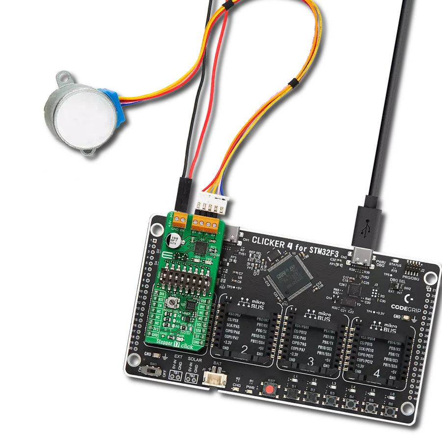
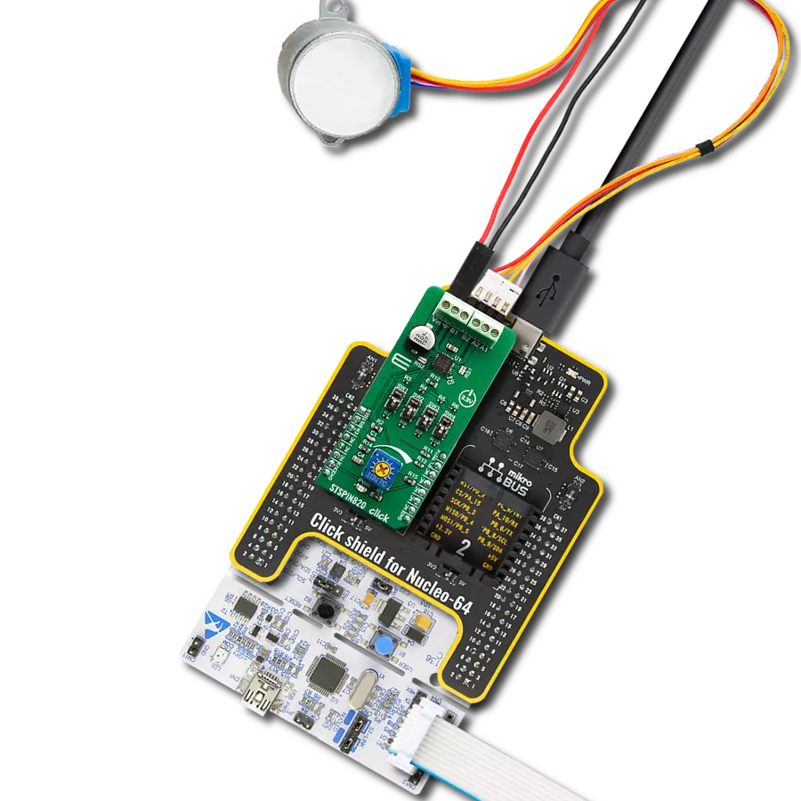
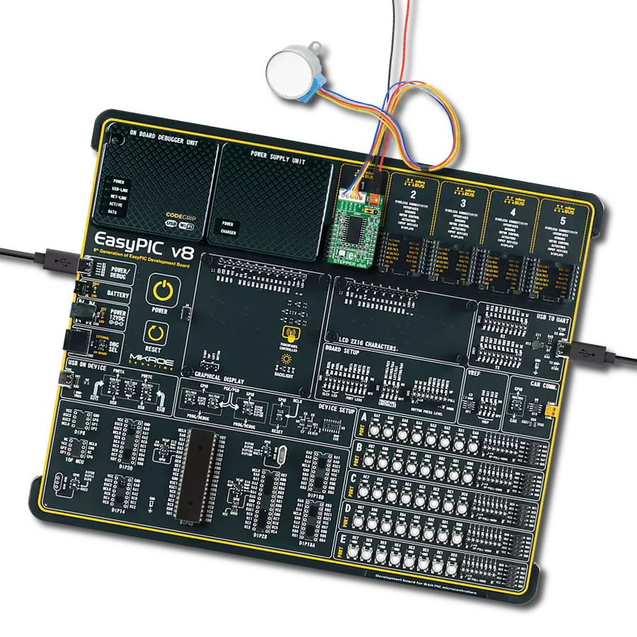
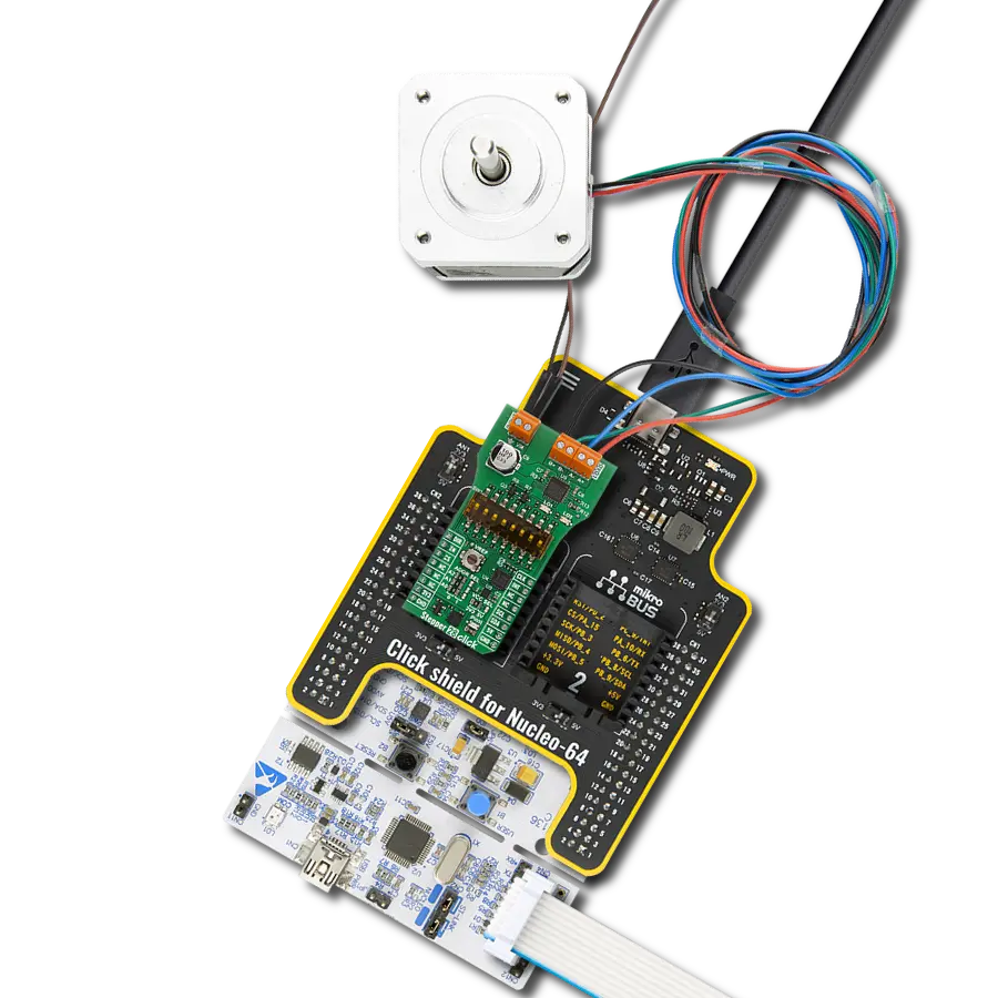
Start by selecting your development board and Click board™. Begin with the Curiosity Nano with PIC18F57Q43 as your development board.


Software Support
Library Description
This library contains API for Driver Click driver.
Key functions:
driver_set_in1- IN1 Set function.driver_set_in2- IN2 Set function.driver_set_in3- IN3 Set function.
Open Source
Code example
The complete application code and a ready-to-use project are available through the NECTO Studio Package Manager for direct installation in the NECTO Studio. The application code can also be found on the MIKROE GitHub account.
/*!
 * \file
 * \brief Driver Click example
 *
 * # Description
 * This application offering a nine-pole spring terminal that can be used to implement and realize a wide range of different applications.
 *
 * The demo application is composed of two sections :
 *
 * ## Application Init
 * Initializes GPIO driver and selects which inputs will be set in operation.
   Bits from 0 to 6 (selectIN) select inputs from IN1 to IN7, respectively.
 *
 * ## Application Task
 * Performs cycles in which selected inputs will be turned on for pulseWidth
   delay time one by one. When one input is turned on, it will be turned off after desired delay time before the next input be turned on.
 *
 * \author MikroE Team
 *
 */
// ------------------------------------------------------------------- INCLUDES

#include "board.h"
#include "log.h"
#include "driver.h"

// ------------------------------------------------------------------ VARIABLES

static driver_t driver;
static log_t logger;

// ------------------------------------------------------ APPLICATION FUNCTIONS

void application_init ( void )
{
    log_cfg_t log_cfg;
    driver_cfg_t cfg;

    /**
     * Logger initialization.
     * Default baud rate: 115200
     * Default log level: LOG_LEVEL_DEBUG
     * @note If USB_UART_RX and USB_UART_TX
     * are defined as HAL_PIN_NC, you will
     * need to define them manually for log to work.
     * See @b LOG_MAP_USB_UART macro definition for detailed explanation.
     */
    LOG_MAP_USB_UART( log_cfg );
    log_init( &logger, &log_cfg );
    log_info(&logger, "---- Application Init ----");

    //  Click initialization.

    driver_cfg_setup( &cfg );
    DRIVER_MAP_MIKROBUS( cfg, MIKROBUS_1 );
    driver_init( &driver, &cfg );
}

void application_task ( void )
{
    uint8_t select_in;
    uint8_t temp;
    uint8_t count;

    select_in = 0x7F;
    temp = 1;

    for (count = 0; count < 7; count++)
    {
        switch ( select_in & temp )
        {
            case 0x01 :
            {
                driver_set_in1( &driver, ENABLE_IN );
                log_printf( &logger, "OUT1 enabled\r\n" );
                Delay_ms ( PULSE_WIDTH );
                driver_set_in1( &driver, DISABLE_IN );
                log_printf( &logger, "OUT1 disabled\r\n" );
                break;
            }
            case 0x02 :
            {
                driver_set_in2( &driver, ENABLE_IN );
                log_printf( &logger, "OUT2 enabled\r\n" );
                Delay_ms ( PULSE_WIDTH );
                driver_set_in2( &driver, DISABLE_IN );
                log_printf( &logger, "OUT2 disabled\r\n" );
                break;
            }
            case 0x04 :
            {
                driver_set_in3( &driver, ENABLE_IN );
                log_printf( &logger, "OUT3 enabled\r\n" );
                Delay_ms ( PULSE_WIDTH );
                driver_set_in3( &driver, DISABLE_IN );
                log_printf( &logger, "OUT3 disabled\r\n" );
                break;
            }
            case 0x08 :
            {
                driver_set_in4( &driver, ENABLE_IN );
                log_printf( &logger, "OUT4 enabled\r\n" );
                Delay_ms ( PULSE_WIDTH );
                driver_set_in4( &driver, DISABLE_IN );
                log_printf( &logger, "OUT4 disabled\r\n" );
                break;
            }
            case 0x10 :
            {
                driver_set_in5( &driver, ENABLE_IN );
                log_printf( &logger, "OUT5 enabled\r\n" );
                Delay_ms ( PULSE_WIDTH );
                driver_set_in5( &driver, DISABLE_IN );
                log_printf( &logger, "OUT5 disabled\r\n" );
                break;
            }
            case 0x20 :
            {
                driver_set_in6( &driver, ENABLE_IN );
                log_printf( &logger, "OUT6 enabled\r\n" );
                Delay_ms ( PULSE_WIDTH );
                driver_set_in6( &driver, DISABLE_IN );
                log_printf( &logger, "OUT6 disabled\r\n" );
                break;
            }
            case 0x40 :
            {
                driver_set_in7( &driver, ENABLE_IN );
                log_printf( &logger, "OUT7 enabled\r\n" );
                Delay_ms ( PULSE_WIDTH );
                driver_set_in7( &driver, DISABLE_IN );
                log_printf( &logger, "OUT7 disabled\r\n" );
                break;
            }
            default :
            {
                break;
            }
        }
        log_printf( &logger, "----------------------\r\n" );
        temp <<= 1;

        Delay_ms ( 1000 );
    }
}

int main ( void )
{
    /* Do not remove this line or clock might not be set correctly. */
    #ifdef PREINIT_SUPPORTED
    preinit();
    #endif

    application_init( );

    for ( ; ; )
    {
        application_task( );
    }

    return 0;
}


// ------------------------------------------------------------------------ END
Additional Support
Resources
Category:Stepper