Measure and report temperature in a digital format with AT30TSE758A and STM32L031K6
Record and store temperature data over time
Published Oct 01, 2024
Click board™
Temp-Log Click
Dev. board
Nucleo 32 with STM32L031K6 MCU
Compiler
NECTO Studio
MCU
STM32L031K6
Monitor temperature in various applications with the highest precision
A
A
Hardware Overview
How does it work?
Temp-Log Click is based on the AT30TSE758A, a 9 to 12bit, ±0.5°C accurate digital temperature sensor with non-volatile registers and integrated serial EEPROM from Microchip. The AT30TSE758A utilizes a band-gap type temperature sensor with an internal sigma-delta ADC to measure and convert the temperature. The internal ADC can be configured to work with a resolution of 9, 10, 11, or 12 bits. This directly affects the size of the temperature measurement steps. However, it should be noted that the higher resolution results in longer conversion times. The measured temperature is calibrated in degrees Celsius. The AT30TSE758A sensor uses the I2C bus for communication with the MCU. The AT30TSE758A sensor is made with power saving in mind. When the shutdown mode is engaged, the power consumption is minimal, and most device sections do not consume any power. The ONE SHOT function allows you to wake up the device, take one measurement, update the registers, and reenter shutdown mode. The 16bit configuration
register is used to configure all the working parameters of the sensor: mode (one-shot mode, normal, and shutdown mode), conversion resolution, the polarity of the ALERT pin, ALERT mode, non-volatile memory busy status, and more. There is also a copy of this register in the non-volatile memory, which can be independently changed. After the power is on, the content of the non-volatile config register will be copied to its volatile counterpart. The non-volatile version of the configuration register contains additional bits for the permanent lock-down and config lock, used to prevent further changes to the configuration parameters. Also, two more 16-bit registers are used to set the high and the low-temperature thresholds, which also have their non-volatile copies. Depending on the ALERT mode bit in the config register, the temperature threshold values in these registers will be used to trigger an event on the ALERT pin, routed to the mikroBUS™ INT pin. This pin is pulled HIGH on this Click, so it is a good idea to configure it as active LOW using the
polarity bit in the config register. The 8Kbit EEPROM section of the AT30TSE758A acts as an additional serial device with its own I2C slave address. The 7-bit I2C address of the serial EEPROM is 1010APP, where “A” corresponds to the status of the A2 address pin. The last two “P” characters correspond to the memory page bits P1 and P0. The remaining two address pin states (A0 and A1) are not required to match when addressing the EEPROM. These bits and the word address byte transmitted via the I2C comprise the 10-bit address field required to map all 1024 bytes available on this device. The EEPROM contains 16 bytes per page and 64 pages in an array. This Click board™ can operate with either 3.3V or 5V logic voltage levels selected via the VCC SEL jumper. This way, both 3.3V and 5V capable MCUs can use the communication lines properly. Also, this Click board™ comes equipped with a library containing easy-to-use functions and an example code that can be used as a reference for further development.

Features overview
Development board
Nucleo 32 with STM32L031K6 MCU board provides an affordable and flexible platform for experimenting with STM32 microcontrollers in 32-pin packages. Featuring Arduino™ Nano connectivity, it allows easy expansion with specialized shields, while being mbed-enabled for seamless integration with online resources. The
board includes an on-board ST-LINK/V2-1 debugger/programmer, supporting USB reenumeration with three interfaces: Virtual Com port, mass storage, and debug port. It offers a flexible power supply through either USB VBUS or an external source. Additionally, it includes three LEDs (LD1 for USB communication, LD2 for power,
and LD3 as a user LED) and a reset push button. The STM32 Nucleo-32 board is supported by various Integrated Development Environments (IDEs) such as IAR™, Keil®, and GCC-based IDEs like AC6 SW4STM32, making it a versatile tool for developers.

Microcontroller Overview
MCU Card / MCU

Architecture
ARM Cortex-M0
MCU Memory (KB)
32
Silicon Vendor
STMicroelectronics
Pin count
32
RAM (Bytes)
8192
You complete me!
Accessories
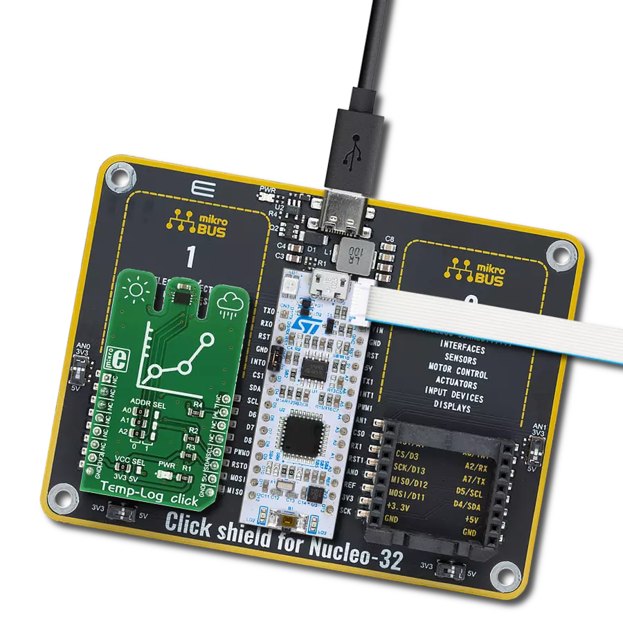
Click Shield for Nucleo-32 is the perfect way to expand your development board's functionalities with STM32 Nucleo-32 pinout. The Click Shield for Nucleo-32 provides two mikroBUS™ sockets to add any functionality from our ever-growing range of Click boards™. We are fully stocked with everything, from sensors and WiFi transceivers to motor control and audio amplifiers. The Click Shield for Nucleo-32 is compatible with the STM32 Nucleo-32 board, providing an affordable and flexible way for users to try out new ideas and quickly create prototypes with any STM32 microcontrollers, choosing from the various combinations of performance, power consumption, and features. The STM32 Nucleo-32 boards do not require any separate probe as they integrate the ST-LINK/V2-1 debugger/programmer and come with the STM32 comprehensive software HAL library and various packaged software examples. This development platform provides users with an effortless and common way to combine the STM32 Nucleo-32 footprint compatible board with their favorite Click boards™ in their upcoming projects.

Used MCU Pins
mikroBUS™ mapper
Take a closer look
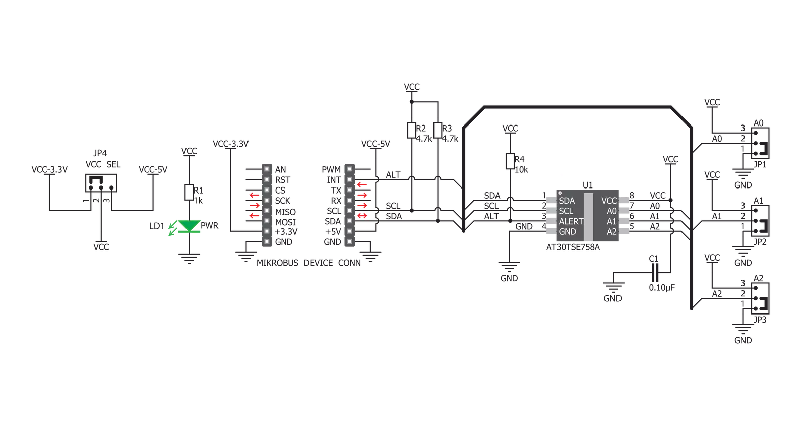
Click board™ Schematic
Step by step
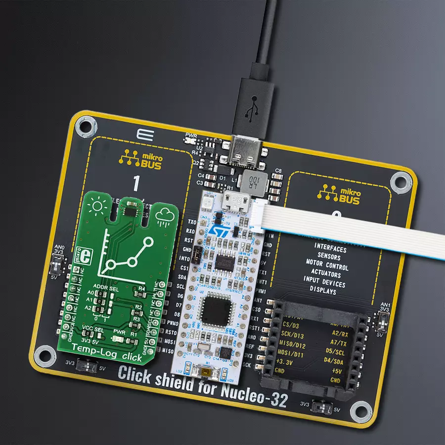
Project assembly

Start by selecting your development board and Click board™. Begin with the Nucleo 32 with STM32L031K6 MCU as your development board.


Track your results in real time
Application Output
1. Application Output - In Debug mode, the 'Application Output' window enables real-time data monitoring, offering direct insight into execution results. Ensure proper data display by configuring the environment correctly using the provided tutorial.

2. UART Terminal - Use the UART Terminal to monitor data transmission via a USB to UART converter, allowing direct communication between the Click board™ and your development system. Configure the baud rate and other serial settings according to your project's requirements to ensure proper functionality. For step-by-step setup instructions, refer to the provided tutorial.

3. Plot Output - The Plot feature offers a powerful way to visualize real-time sensor data, enabling trend analysis, debugging, and comparison of multiple data points. To set it up correctly, follow the provided tutorial, which includes a step-by-step example of using the Plot feature to display Click board™ readings. To use the Plot feature in your code, use the function: plot(*insert_graph_name*, variable_name);. This is a general format, and it is up to the user to replace 'insert_graph_name' with the actual graph name and 'variable_name' with the parameter to be displayed.

Software Support
Library Description
This library contains API for Temp-Log Click driver.
Key functions:
temp_log_read_temp_dec- This function reads decimal value of temp.temp_log_convert_to_celsius- This function converts temperature data to celsius value.temp_log_get_alert- This function alerts user if temperature limit is alarming.
Open Source
Code example
The complete application code and a ready-to-use project are available through the NECTO Studio Package Manager for direct installation in the NECTO Studio. The application code can also be found on the MIKROE GitHub account.
/*!
 * \file
 * \brief TempLog Click example
 *
 * # Description
 * This example returns values of the temperature from the sensor.
 *
 * The demo application is composed of two sections :
 *
 * ## Application Init
 * Initializes Click driver.
 *
 * ## Application Task
 * Reads temperature from temperature register in decimal value in 9-bit resolution,
 * converts that decimal value in celsius value and checks Alert pin witch goes active (low)
 * if the measured temperature meets or exceeds the high temperature limit.
 *
 *
 * \author MikroE Team
 *
 */
// ------------------------------------------------------------------- INCLUDES

#include "board.h"
#include "log.h"
#include "templog.h"

// ------------------------------------------------------------------ VARIABLES

static templog_t templog;
static log_t logger;

// ------------------------------------------------------ APPLICATION FUNCTIONS

void application_init ( void )
{
    log_cfg_t log_cfg;
    templog_cfg_t cfg;

    /**
     * Logger initialization.
     * Default baud rate: 115200
     * Default log level: LOG_LEVEL_DEBUG
     * @note If USB_UART_RX and USB_UART_TX
     * are defined as HAL_PIN_NC, you will
     * need to define them manually for log to work.
     * See @b LOG_MAP_USB_UART macro definition for detailed explanation.
     */
    LOG_MAP_USB_UART( log_cfg );
    log_init( &logger, &log_cfg );
    log_info( &logger, " Application Init " );

    // Click initialization.
    templog_cfg_setup ( &cfg );
    TEMPLOG_MAP_MIKROBUS( cfg, MIKROBUS_1 );
    if ( TEMPLOG_OK != templog_init ( &templog, &cfg ) )
    {
        log_error( &logger, " Communication init." );
        for ( ; ; );
    }

    templog_default_cfg ( &templog );

    log_info( &logger, " Application Task " );
}

void application_task ( void )
{
    uint16_t temp_in_dec = 0;
    float temp_in_cels = 0;

    temp_in_dec = temp_log_read_temp_dec( &templog, TEMP_LOG_RESOLUTION_9_BITS );
    temp_in_cels = temp_log_convert_to_celsius( temp_in_dec );

    log_printf( &logger, "Temperature in celsius value is: %.2f\r\n", temp_in_cels );

    if ( temp_log_get_alert( &templog ) == 0 )
    {
        log_printf( &logger, "TEMPERATURE LIMIT ALARMING!\r\n" );
    }

    Delay_ms ( 1000 );
}

int main ( void )
{
    /* Do not remove this line or clock might not be set correctly. */
    #ifdef PREINIT_SUPPORTED
    preinit();
    #endif

    application_init( );

    for ( ; ; )
    {
        application_task( );
    }

    return 0;
}

// ------------------------------------------------------------------------ END
Additional Support
Resources
Category:Temperature & humidity


