Your shield against interference for flawless USB communication based on ISOUSB111 and STM32F031K6
Redefining USB to UART connectivity for a smoother data exchange
Published Oct 01, 2024
Click board™
USB UART ISO Click
Dev. board
Nucleo 32 with STM32F031K6 MCU
Compiler
NECTO Studio
MCU
STM32F031K6
Complete USB-to-UART isolated solution for engineers and developers working on projects that demand secure and reliable data communication.
A
A
Hardware Overview
How does it work?
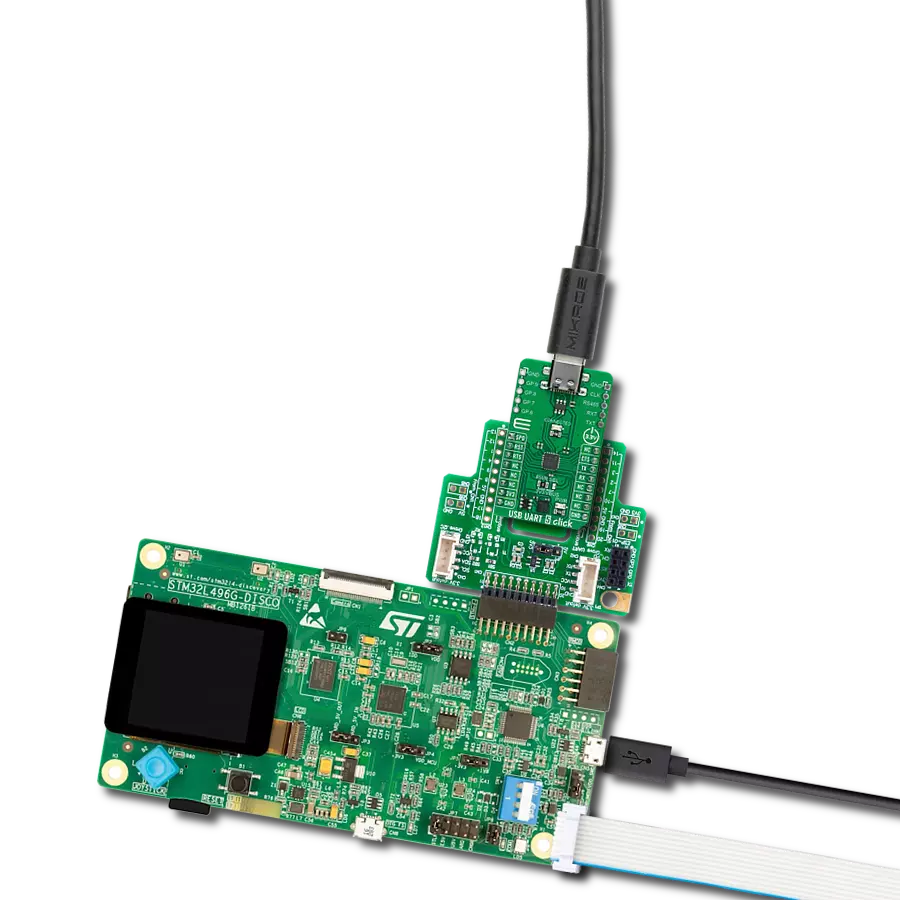
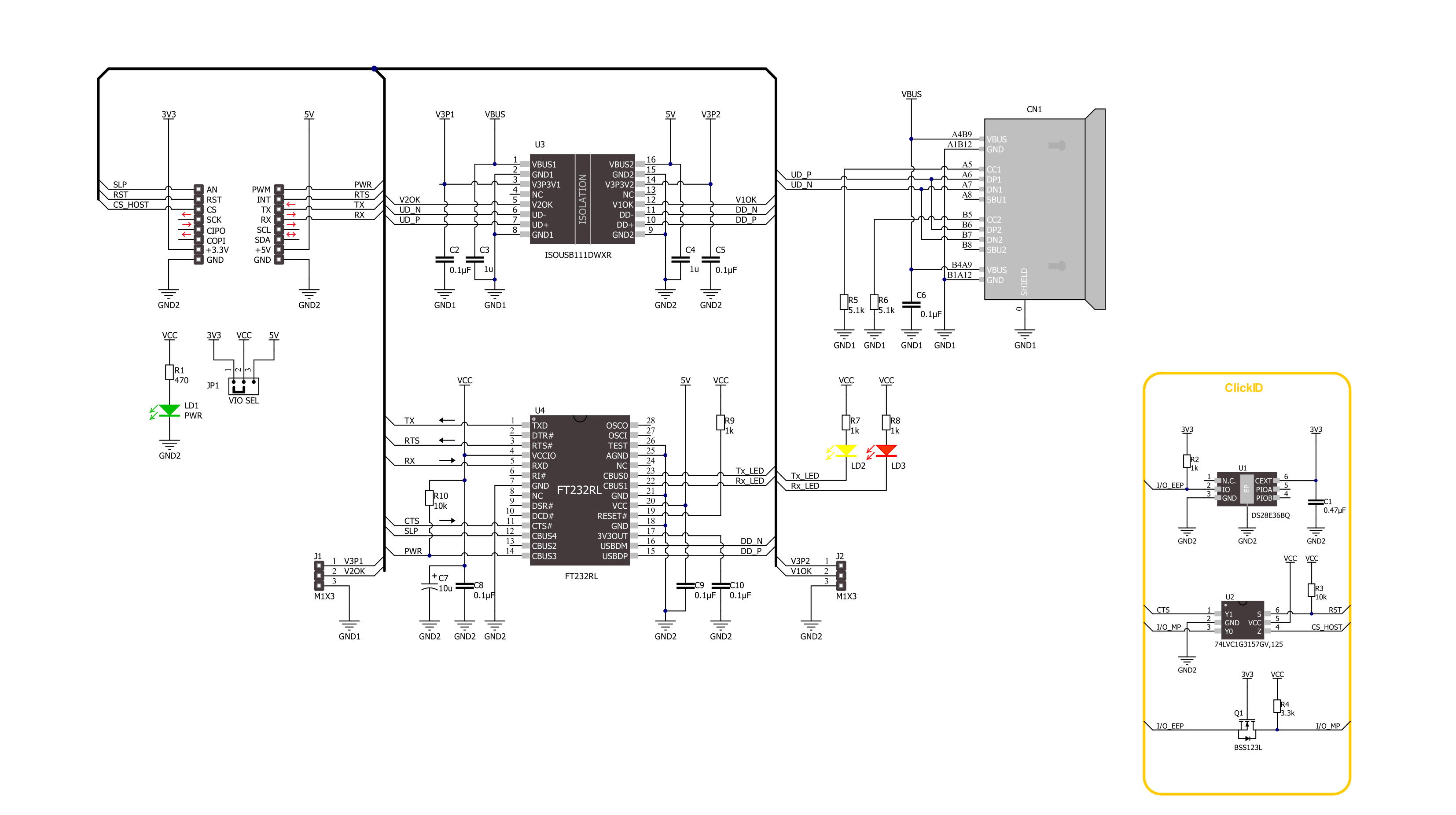
USB UART ISO Click is based on the ISOUSB111, a full/low-speed isolated USB repeater from Texas Instruments. It is a galvanically isolated USB 2.0 repeater that supports automatic speed connection detection, reflection of pull-ups/pull-downs, and link power management. The repeater isolates D+ and D- USB bus lines and supports automatic role reversal. This means that, after disconnection, if a new connection is detected on the upstream-facing port, then the upstream and downstream port definitions are reversed. This device uses a silicon dioxide insulation barrier with a withstand voltage of up to 5000VRMS and a working voltage of 1500VRMS, thus protecting from high voltages and preventing noise currents
from the bus entering the local ground. This USB repeater also comes with a pair of unpopulated headers for testing purposes for both sides of the isolation barrier. Both headers contain a GND (for both sides), a powered-up indicator pin (V1OK or V2OK), and power supply pins for both sides. USB UART ISO Click is equipped with a USB type C connector, which can connect a USB device to a host MCU over the UART bridge and a USB isolated repeater. The FT232R is a well-known UART bridge chip on which the entire USB protocol is handled on the chip. There is driver support for all common operating systems. The UART chip comes with a pair of UART RX and TX LEDs to visually present UART data flow. USB
UART ISO Click uses a standard UART interface to establish communication of the connected USB device with the host MCU over the UART bridge and an isolated USB repeater. In addition, the UART flow control pins RTS and CTS are available. Additionally, there is an SLP pin for Sleep mode control and a PWR pin as a power enable pin. This Click board™ can operate with either 3.3V or 5V logic voltage levels selected via the VIO SEL jumper. This way, both 3.3V and 5V capable MCUs can use the communication lines properly. Also, this Click board™ comes equipped with a library containing easy-to-use functions and an example code that can be used for further development.

Features overview
Development board
Nucleo 32 with STM32F031K6 MCU board provides an affordable and flexible platform for experimenting with STM32 microcontrollers in 32-pin packages. Featuring Arduino™ Nano connectivity, it allows easy expansion with specialized shields, while being mbed-enabled for seamless integration with online resources. The
board includes an on-board ST-LINK/V2-1 debugger/programmer, supporting USB reenumeration with three interfaces: Virtual Com port, mass storage, and debug port. It offers a flexible power supply through either USB VBUS or an external source. Additionally, it includes three LEDs (LD1 for USB communication, LD2 for power,
and LD3 as a user LED) and a reset push button. The STM32 Nucleo-32 board is supported by various Integrated Development Environments (IDEs) such as IAR™, Keil®, and GCC-based IDEs like AC6 SW4STM32, making it a versatile tool for developers.

Microcontroller Overview
MCU Card / MCU

Architecture
ARM Cortex-M0
MCU Memory (KB)
32
Silicon Vendor
STMicroelectronics
Pin count
32
RAM (Bytes)
4096
You complete me!
Accessories
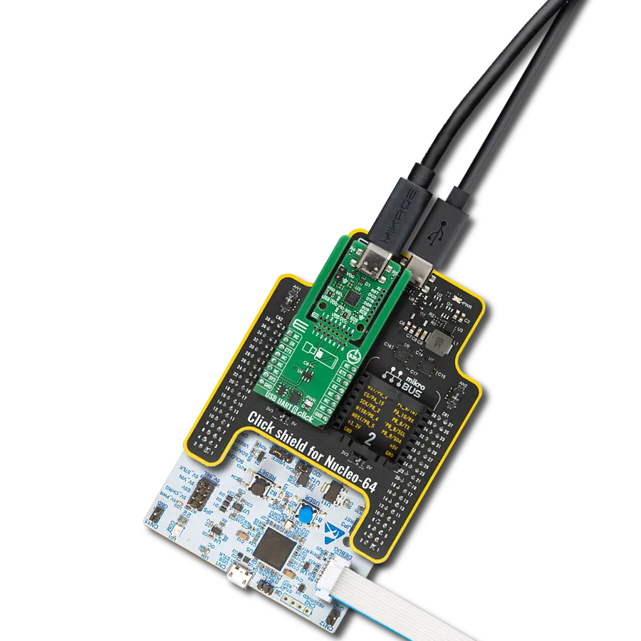
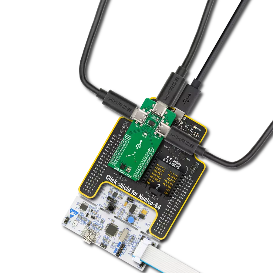
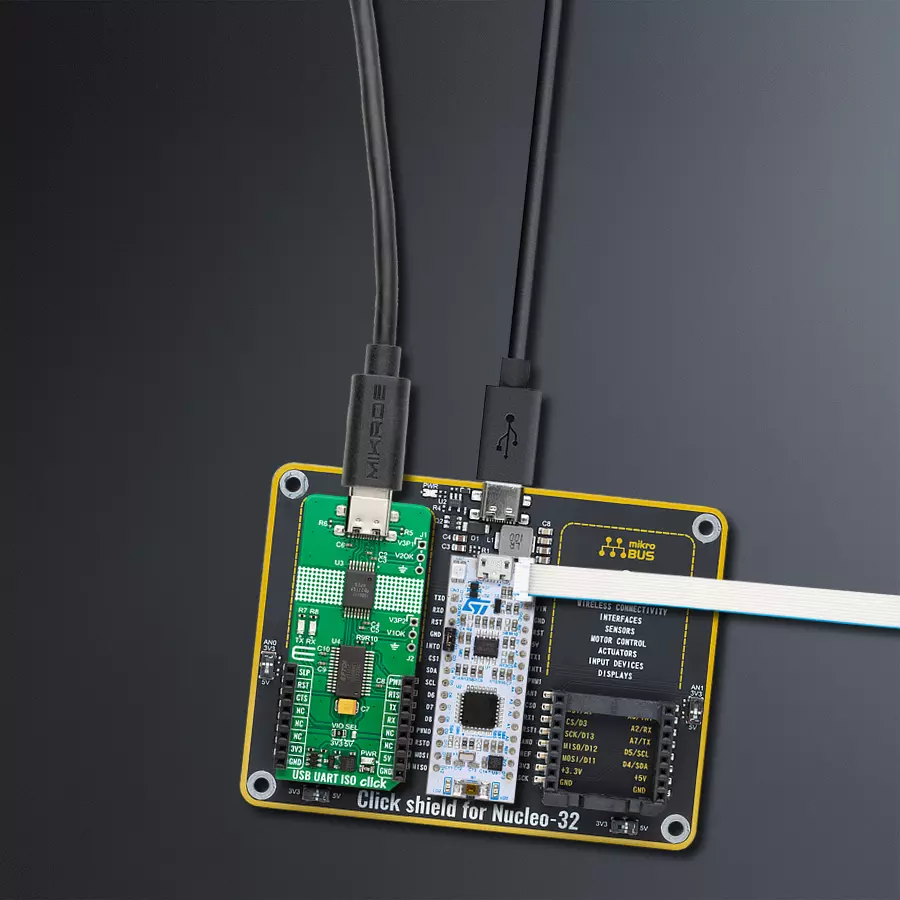
Click Shield for Nucleo-32 is the perfect way to expand your development board's functionalities with STM32 Nucleo-32 pinout. The Click Shield for Nucleo-32 provides two mikroBUS™ sockets to add any functionality from our ever-growing range of Click boards™. We are fully stocked with everything, from sensors and WiFi transceivers to motor control and audio amplifiers. The Click Shield for Nucleo-32 is compatible with the STM32 Nucleo-32 board, providing an affordable and flexible way for users to try out new ideas and quickly create prototypes with any STM32 microcontrollers, choosing from the various combinations of performance, power consumption, and features. The STM32 Nucleo-32 boards do not require any separate probe as they integrate the ST-LINK/V2-1 debugger/programmer and come with the STM32 comprehensive software HAL library and various packaged software examples. This development platform provides users with an effortless and common way to combine the STM32 Nucleo-32 footprint compatible board with their favorite Click boards™ in their upcoming projects.

Used MCU Pins
mikroBUS™ mapper
Take a closer look
Click board™ Schematic
Step by step
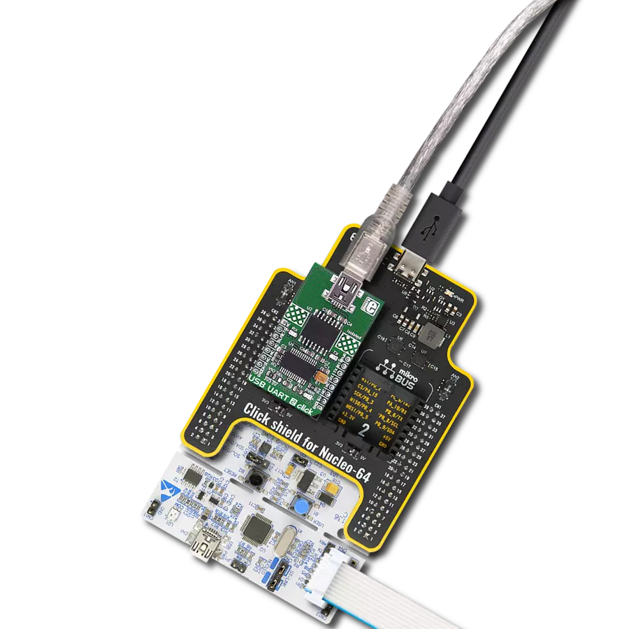
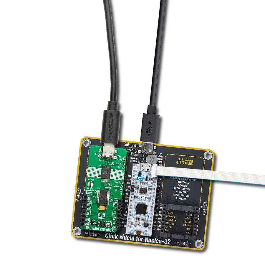
Project assembly

Start by selecting your development board and Click board™. Begin with the Nucleo 32 with STM32F031K6 MCU as your development board.


Track your results in real time
Application Output
1. Application Output - In Debug mode, the 'Application Output' window enables real-time data monitoring, offering direct insight into execution results. Ensure proper data display by configuring the environment correctly using the provided tutorial.

2. UART Terminal - Use the UART Terminal to monitor data transmission via a USB to UART converter, allowing direct communication between the Click board™ and your development system. Configure the baud rate and other serial settings according to your project's requirements to ensure proper functionality. For step-by-step setup instructions, refer to the provided tutorial.

3. Plot Output - The Plot feature offers a powerful way to visualize real-time sensor data, enabling trend analysis, debugging, and comparison of multiple data points. To set it up correctly, follow the provided tutorial, which includes a step-by-step example of using the Plot feature to display Click board™ readings. To use the Plot feature in your code, use the function: plot(*insert_graph_name*, variable_name);. This is a general format, and it is up to the user to replace 'insert_graph_name' with the actual graph name and 'variable_name' with the parameter to be displayed.

Software Support
Library Description
This library contains API for USB UART ISO Click driver.
Key functions:
usbuartiso_generic_write- USB UART ISO data writing function.usbuartiso_generic_read- USB UART ISO data reading function.
Open Source
Code example
The complete application code and a ready-to-use project are available through the NECTO Studio Package Manager for direct installation in the NECTO Studio. The application code can also be found on the MIKROE GitHub account.
/*!
 * @file main.c
 * @brief USB UART ISO Click Example.
 *
 * # Description
 * This example demonstrates the use of USB UART ISO Click board by processing
 * the incoming data and displaying them on the USB UART.
 *
 * The demo application is composed of two sections :
 *
 * ## Application Init
 * Initializes the driver and performs the Click default configuration.
 *
 * ## Application Task
 * Any data which the host PC sends via UART Terminal
 * will be sent over USB to the Click board and then it will be read and
 * echoed back by the MCU to the PC where the terminal program will display it.
 * Results are being sent to the UART Terminal, where you can track their changes.
 *
 * @author Nenad Filipovic
 *
 */

#include "board.h"
#include "log.h"
#include "usbuartiso.h"

static usbuartiso_t usbuartiso;
static log_t logger;

void application_init ( void )
{
    log_cfg_t log_cfg;  /**< Logger config object. */
    usbuartiso_cfg_t usbuartiso_cfg;  /**< Click config object. */

    /**
     * Logger initialization.
     * Default baud rate: 115200
     * Default log level: LOG_LEVEL_DEBUG
     * @note If USB_UART_RX and USB_UART_TX
     * are defined as HAL_PIN_NC, you will
     * need to define them manually for log to work.
     * See @b LOG_MAP_USB_UART macro definition for detailed explanation.
     */
    LOG_MAP_USB_UART( log_cfg );
    log_init( &logger, &log_cfg );
    log_info( &logger, " Application Init " );

    // Click initialization.
    usbuartiso_cfg_setup( &usbuartiso_cfg );
    USBUARTISO_MAP_MIKROBUS( usbuartiso_cfg, MIKROBUS_1 );
    if ( UART_ERROR == usbuartiso_init( &usbuartiso, &usbuartiso_cfg ) )
    {
        log_error( &logger, " Communication init." );
        for ( ; ; );
    }

    usbuartiso_default_cfg ( &usbuartiso );
    log_info( &logger, " Application Task " );
}

void application_task ( void )
{
    char rx_data = 0;
    if ( usbuartiso_generic_read ( &usbuartiso, &rx_data, 1 ) )
    {
        if ( usbuartiso_generic_write ( &usbuartiso, &rx_data, 1 ) )
        {
            log_printf( &logger, "%c", rx_data );
        }
    }
}

int main ( void )
{
    /* Do not remove this line or clock might not be set correctly. */
    #ifdef PREINIT_SUPPORTED
    preinit();
    #endif

    application_init( );

    for ( ; ; )
    {
        application_task( );
    }

    return 0;
}

// ------------------------------------------------------------------------ END
Additional Support
Resources
Category:USB