Achieve versatility in motor control with STSPIN250 and STM32G474RE
Unleash the power of brushed DC motor control!
Published Nov 08, 2024
Click board™
STSPIN250 Click
Dev. board
Nucleo 64 with STM32G474RE MCU
Compiler
NECTO Studio
MCU
STM32G474RE
Experience enhanced motor performance with our brushed DC motor driver, optimizing efficiency, reducing wear, and extending the operational lifespan of your motors
A
A
Hardware Overview
How does it work?
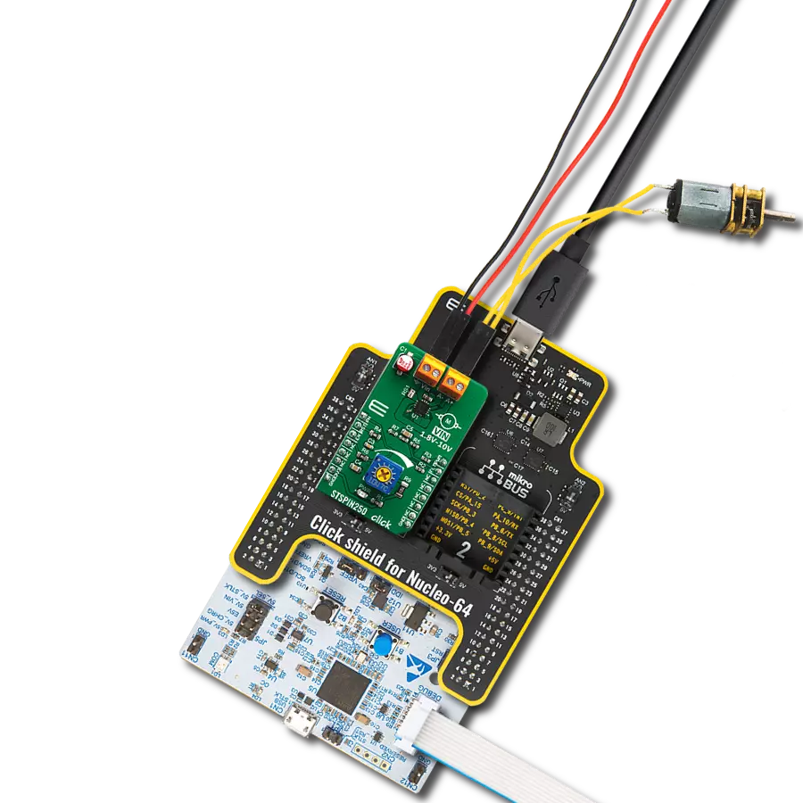
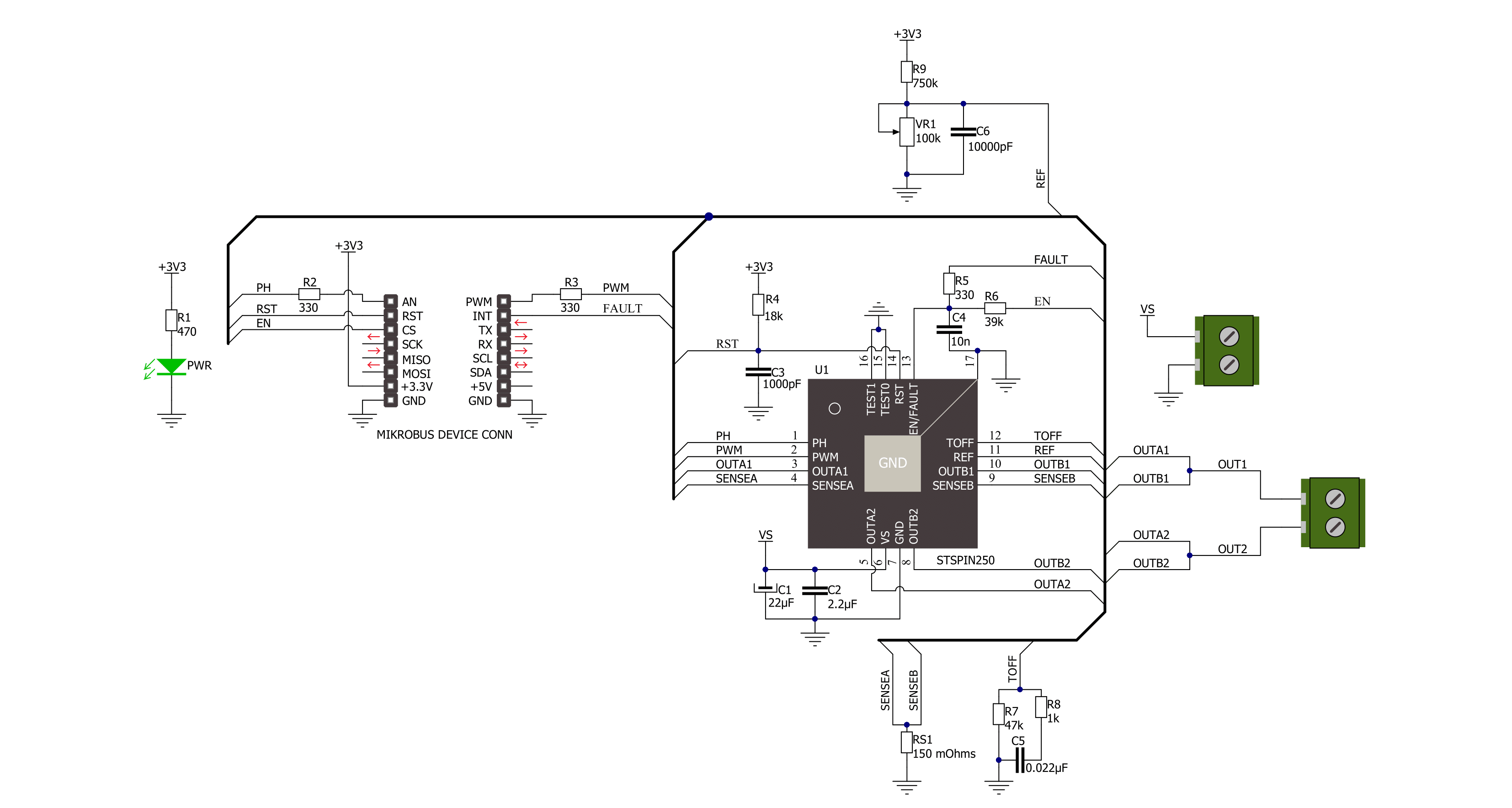
STSPIN250 Click is based on the STSPIN250, a low voltage DC brushed motor driver by STMicroelectronics. This device integrates two full-bridge MOSFET channels in a parallel configuration, sustaining up to 2.6A. This IC targets battery-powered applications, featuring optimizations toward lowered power consumption. It has a PWM current controller with a fixed OFF time, during which the current decay sequence is performed. This effectively limits the current through the connected load (motor). The OFF (decay) time is approximately 40 µs on this Click board™. The PWM current controller compares the voltage across the sense resistor (VSENS) and the VREF voltage, which is adjustable on STSPIN250 click. When VSENS exceeds the VREF voltage, the current limiting is triggered, and the OFF timer starts counting. The decay sequence is performed. Knowing the RSENS, it can be easily calculated how much voltage should be applied to the REF pin of the STSPIN250 to limit the current according to ILOAD. For example, if 0.388V is applied at the VREF pin, the current limit will be maxed out to 2.58A. The onboard
potentiometer allows you to adjust the VREF voltage according to needs simply. The connected motor can be controlled by using these pins: PWM, PH, RST, and EN/INT. The PH pin determines the direction of the current. If set to a HIGH logic level, the current will flow in one direction, and vice-versa: when a LOW logic level is applied, the current will reverse its direction. This pin is routed to the AN pin of the mikroBUS™ and labeled as PH. PWM pin can be used to regulate the speed of the rotation. When this pin has a LOW logic level, the current will start circulating through the low-side (LS) MOSFETs and the motor coil. When there is a HIGH logic level on this pin, the current will flow through the load, depending on the logic state of the PH pin. A higher duty cycle percentage will result in higher angular speed. While the current decay sequence is performed, the logic states on the input pins will be disregarded until the decay timer expires. The decay time is fixed to approximately 40 µs on this Click board™. The STBY/RESET (RST) pin of the STSPIN250 is used to set both bridge outputs in HIGH-Z mode, disconnecting the power supply
from the output stage. This pin allows lower average power consumption as no current can flow from the power supply to the motor. This pin is routed to the RST pin of the mikroBUS™. The EN/FAULT (EN) pin has a double purpose: when set to a high logic level, it acts as a chip enable, allowing the device to operate. In the case of a fault condition on the IC, it will be asserted to a LOW logic level, acting as an interrupt pin. A restart attempt will be made after a timeout period defined by the external capacitor and resistor values. This pin is routed to the CS and INT pin of the mikroBUS™, allowing the host MCU to use both functions. These pins are labeled EN and FLT on the Click board™, respectively. The motor power supply can be connected to the input terminal labeled as VIN and should be within the range of 1.8V to 10V. The motor can be connected at the second terminal, between two poles labeled as A+ and A-. The Click board™ requires an external power supply for the motor to work. However, it also requires 3.3V from the mikroBUS™ rail.

Features overview
Development board
Nucleo-64 with STM32G474R MCU offers a cost-effective and adaptable platform for developers to explore new ideas and prototype their designs. This board harnesses the versatility of the STM32 microcontroller, enabling users to select the optimal balance of performance and power consumption for their projects. It accommodates the STM32 microcontroller in the LQFP64 package and includes essential components such as a user LED, which doubles as an ARDUINO® signal, alongside user and reset push-buttons, and a 32.768kHz crystal oscillator for precise timing operations. Designed with expansion and flexibility in mind, the Nucleo-64 board features an ARDUINO® Uno V3 expansion connector and ST morpho extension pin
headers, granting complete access to the STM32's I/Os for comprehensive project integration. Power supply options are adaptable, supporting ST-LINK USB VBUS or external power sources, ensuring adaptability in various development environments. The board also has an on-board ST-LINK debugger/programmer with USB re-enumeration capability, simplifying the programming and debugging process. Moreover, the board is designed to simplify advanced development with its external SMPS for efficient Vcore logic supply, support for USB Device full speed or USB SNK/UFP full speed, and built-in cryptographic features, enhancing both the power efficiency and security of projects. Additional connectivity is
provided through dedicated connectors for external SMPS experimentation, a USB connector for the ST-LINK, and a MIPI® debug connector, expanding the possibilities for hardware interfacing and experimentation. Developers will find extensive support through comprehensive free software libraries and examples, courtesy of the STM32Cube MCU Package. This, combined with compatibility with a wide array of Integrated Development Environments (IDEs), including IAR Embedded Workbench®, MDK-ARM, and STM32CubeIDE, ensures a smooth and efficient development experience, allowing users to fully leverage the capabilities of the Nucleo-64 board in their projects.

Microcontroller Overview
MCU Card / MCU

Architecture
ARM Cortex-M4
MCU Memory (KB)
512
Silicon Vendor
STMicroelectronics
Pin count
64
RAM (Bytes)
128k
You complete me!
Accessories
Click Shield for Nucleo-64 comes equipped with two proprietary mikroBUS™ sockets, allowing all the Click board™ devices to be interfaced with the STM32 Nucleo-64 board with no effort. This way, Mikroe allows its users to add any functionality from our ever-growing range of Click boards™, such as WiFi, GSM, GPS, Bluetooth, ZigBee, environmental sensors, LEDs, speech recognition, motor control, movement sensors, and many more. More than 1537 Click boards™, which can be stacked and integrated, are at your disposal. The STM32 Nucleo-64 boards are based on the microcontrollers in 64-pin packages, a 32-bit MCU with an ARM Cortex M4 processor operating at 84MHz, 512Kb Flash, and 96KB SRAM, divided into two regions where the top section represents the ST-Link/V2 debugger and programmer while the bottom section of the board is an actual development board. These boards are controlled and powered conveniently through a USB connection to program and efficiently debug the Nucleo-64 board out of the box, with an additional USB cable connected to the USB mini port on the board. Most of the STM32 microcontroller pins are brought to the IO pins on the left and right edge of the board, which are then connected to two existing mikroBUS™ sockets. This Click Shield also has several switches that perform functions such as selecting the logic levels of analog signals on mikroBUS™ sockets and selecting logic voltage levels of the mikroBUS™ sockets themselves. Besides, the user is offered the possibility of using any Click board™ with the help of existing bidirectional level-shifting voltage translators, regardless of whether the Click board™ operates at a 3.3V or 5V logic voltage level. Once you connect the STM32 Nucleo-64 board with our Click Shield for Nucleo-64, you can access hundreds of Click boards™, working with 3.3V or 5V logic voltage levels.

DC Gear Motor - 430RPM (3-6V) represents an all-in-one combination of a motor and gearbox, where the addition of gear leads to a reduction of motor speed while increasing the torque output. This gear motor has a spur gearbox, making it a highly reliable solution for applications with lower torque and speed requirements. The most critical parameters for gear motors are speed, torque, and efficiency, which are, in this case, 520RPM with no load and 430RPM at maximum efficiency, alongside a current of 60mA and a torque of 50g.cm. Rated for a 3-6V operational voltage range and clockwise/counterclockwise rotation direction, this motor represents an excellent solution for many functions initially performed by brushed DC motors in robotics, medical equipment, electric door locks, and much more.

Used MCU Pins
mikroBUS™ mapper
Take a closer look
Click board™ Schematic
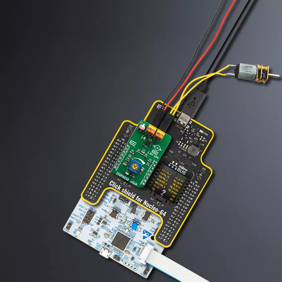
Step by step
Project assembly
Start by selecting your development board and Click board™. Begin with the Nucleo 64 with STM32G474RE MCU as your development board.


Track your results in real time
Application Output
1. Application Output - In Debug mode, the 'Application Output' window enables real-time data monitoring, offering direct insight into execution results. Ensure proper data display by configuring the environment correctly using the provided tutorial.

2. UART Terminal - Use the UART Terminal to monitor data transmission via a USB to UART converter, allowing direct communication between the Click board™ and your development system. Configure the baud rate and other serial settings according to your project's requirements to ensure proper functionality. For step-by-step setup instructions, refer to the provided tutorial.

3. Plot Output - The Plot feature offers a powerful way to visualize real-time sensor data, enabling trend analysis, debugging, and comparison of multiple data points. To set it up correctly, follow the provided tutorial, which includes a step-by-step example of using the Plot feature to display Click board™ readings. To use the Plot feature in your code, use the function: plot(*insert_graph_name*, variable_name);. This is a general format, and it is up to the user to replace 'insert_graph_name' with the actual graph name and 'variable_name' with the parameter to be displayed.

Software Support
Library Description
This library contains API for STSPIN250 Click driver.
Key functions:
stspin250_set_ph- This function regulates Direction control pin state. It controls direction of the currentstspin250_enable- This function regulates enable pin statestspin250_reset- This function regulates reset pin state
Open Source
Code example
The complete application code and a ready-to-use project are available through the NECTO Studio Package Manager for direct installation in the NECTO Studio. The application code can also be found on the MIKROE GitHub account.
/*!
 * @file
 * @brief Stspin250 Click example
 *
 * # Description
 * This application enables usage of brushed DC motor driver with
 * the current limiting and current sensing.
 *
 * The demo application is composed of two sections :
 *
 * ## Application Init
 * Initialization driver init, PWM init and enable device
 *
 * ## Application Task
 * This is a example which demonstrates the use of Stspin250 Click board.
 * Stspin250 Click communicates with register via PWM interface.
 * It shows moving in the left direction from slow to fast speed
 * and from fast to slow speed.
 * Results are being sent to the Usart Terminal where you can track their changes.
 *
 * @author Nikola Peric
 *
 */
// ------------------------------------------------------------------- INCLUDES

#include "board.h"
#include "log.h"
#include "stspin250.h"

// ------------------------------------------------------------------ VARIABLES

static stspin250_t stspin250;
static log_t logger;
uint8_t motor_direction = 1;

// ------------------------------------------------------ APPLICATION FUNCTIONS

void application_init ( void )
{
    log_cfg_t log_cfg;
    stspin250_cfg_t cfg;

    /**
     * Logger initialization.
     * Default baud rate: 115200
     * Default log level: LOG_LEVEL_DEBUG
     * @note If USB_UART_RX and USB_UART_TX
     * are defined as HAL_PIN_NC, you will
     * need to define them manually for log to work.
     * See @b LOG_MAP_USB_UART macro definition for detailed explanation.
     */
    LOG_MAP_USB_UART( log_cfg );
    log_init( &logger, &log_cfg );
    log_info( &logger, "---- Application Init ----" );

    //  Click initialization.

    stspin250_cfg_setup( &cfg );
    STSPIN250_MAP_MIKROBUS( cfg, MIKROBUS_1 );
    stspin250_init( &stspin250, &cfg );

    stspin250_enable( &stspin250, STSPIN250_DEVICE_ENABLE );
    stspin250_set_duty_cycle ( &stspin250, 0.0 );

    stspin250_pwm_start( &stspin250 );
    log_info( &logger, "---- Application Task ----" );
    Delay_ms ( 500 );
}

void application_task ( void )
{
    static int8_t duty_cnt = 1;
    static int8_t duty_inc = 1;
    float duty = duty_cnt / 10.0;

    if ( motor_direction == 1 )
    {
        stspin250_set_ph( &stspin250, 1 );
        log_printf( &logger, "> CLOCKWISE <\r\n" );
    }
    else
    {
        stspin250_set_ph( &stspin250, 0 );
        log_printf( &logger, "> COUNTER CLOCKWISE <\r\n" );
    }

    stspin250_set_duty_cycle ( &stspin250, duty );
    log_printf( &logger, "Duty: %d%%\r\n", ( uint16_t )( duty_cnt * 10 ) );
    Delay_ms ( 500 );

    if ( 10 == duty_cnt )
    {
        duty_inc = -1;
    }
    else if ( 0 == duty_cnt )
    {
        duty_inc = 1;
        if ( motor_direction == 1 )
        {
            motor_direction = 0;
        }
        else if ( motor_direction == 0 )
        {
            motor_direction = 1;
        }
    }
    duty_cnt += duty_inc;
}

int main ( void )
{
    /* Do not remove this line or clock might not be set correctly. */
    #ifdef PREINIT_SUPPORTED
    preinit();
    #endif

    application_init( );

    for ( ; ; )
    {
        application_task( );
    }

    return 0;
}


// ------------------------------------------------------------------------ END


