Manage the operation of two-phase bipolar stepper motors with TB67S269FTG and STM32G474RE
Two-phase bipolar stepping motor driver using a PWM chopper

Published Nov 08, 2024
Click board™
Stepper 4 click
Dev. board
Nucleo 64 with STM32G474RE MCU
Compiler
NECTO Studio
MCU
STM32G474RE
User-friendly solution for controlling bipolar stepper motors featuring advanced technologies that ensure efficient, precise, and noiseless operation
A
A
Hardware Overview
How does it work?
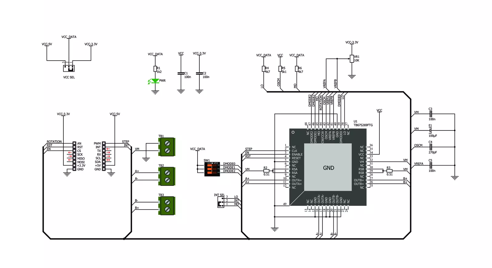
Stepper 4 Click is based on the TB67S269FTG, a bipolar stepper motor driver IC with a translator section from Toshiba Semiconductor. This highly integrated IC offers a very simple bipolar stepper motor control interface, thanks to the integrated translator section. This section controls the output drivers, providing smooth action of the stepper motor. By controlling the current intensity and its decay throughout the rotation cycle, a constant torque is achieved for every position. This IC features a high-efficiency motor current control mechanism (Advanced Dynamic Mixed Decay), which results in the optimal ripple while regulating the motor current. The current is limited by the value of the sensing resistor and a reference voltage at the VREF pins. It is possible to adjust the reference voltage via the onboard potentiometer labeled as torque from 0V to 3.3V, changing the current limit through the motor coils, thus changing the torque. The absolute current limit on this IC is 2A, after which the overcurrent protection is activated. A LOW to HIGH transition
(rising edge) on the CLK pin of the TB67S269FTG IC will perform one rotational step. The direction of the rotation is controlled by the logic state on the CW/CCW pin (routed to the mikroBUS™ AN pin, labeled as DIR). The step size is determined by three pins: DMODE0, DMODE1, and DMODE2. It is possible to work with seven movement step sizes, ranging from full to 1/32 step size. These pins are routed to the DIP switch labeled as STEP MODE, allowing step size to be selected by moving each of them. The ENABLE pin allows the host MCU to turn on or off the output stages of the TB67S269FTG IC. Asserting this pin to a HIGH logic level enables the output stage. The RESET pin is used to reset the electrical angle to the initial position and is active at HIGH. The ENABLE pin is routed to the CS (labeled as EN), while the RESET pin is routed to the RST pin of the mikroBUS™, allowing the host MCU to control the IC via these pins. The TB67S269FTG offers monitoring of the electrical angle and fault condition signaling. These two pins are routed to the SMD jumper labeled as INT SEL.
While in the MO position, the angle monitoring pin will be routed to the mikroBUS™ INT pin. If the jumper is set at the LO position, it will route the LO pin to the INT pin of the mikroBUS™, allowing faulty conditions, such as thermal or overcurrent failure, to be reported. These pins feature a pull-up resistor and will have a LOW logic level when asserted. This Click board™ can be interfaced with 3.3V and 5V MCUs, thanks to an SMD jumper labeled VCC SEL. It is enough to move the SMD jumper to the appropriate position (3V3 or 5V), and the logic voltage level of the communication signals will be properly set for both types of MCUs. The Click board™ is equipped with the input and output screw terminals. The terminal labeled TB1 on the schematic connects the external power supply, which should stay in the range from 10V to 35V. The stepper motor can be connected securely via the TB2 and TB3 screw terminals, with their input terminals labeled as A+, A-, and B+, B-.

Features overview
Development board
Nucleo-64 with STM32G474R MCU offers a cost-effective and adaptable platform for developers to explore new ideas and prototype their designs. This board harnesses the versatility of the STM32 microcontroller, enabling users to select the optimal balance of performance and power consumption for their projects. It accommodates the STM32 microcontroller in the LQFP64 package and includes essential components such as a user LED, which doubles as an ARDUINO® signal, alongside user and reset push-buttons, and a 32.768kHz crystal oscillator for precise timing operations. Designed with expansion and flexibility in mind, the Nucleo-64 board features an ARDUINO® Uno V3 expansion connector and ST morpho extension pin
headers, granting complete access to the STM32's I/Os for comprehensive project integration. Power supply options are adaptable, supporting ST-LINK USB VBUS or external power sources, ensuring adaptability in various development environments. The board also has an on-board ST-LINK debugger/programmer with USB re-enumeration capability, simplifying the programming and debugging process. Moreover, the board is designed to simplify advanced development with its external SMPS for efficient Vcore logic supply, support for USB Device full speed or USB SNK/UFP full speed, and built-in cryptographic features, enhancing both the power efficiency and security of projects. Additional connectivity is
provided through dedicated connectors for external SMPS experimentation, a USB connector for the ST-LINK, and a MIPI® debug connector, expanding the possibilities for hardware interfacing and experimentation. Developers will find extensive support through comprehensive free software libraries and examples, courtesy of the STM32Cube MCU Package. This, combined with compatibility with a wide array of Integrated Development Environments (IDEs), including IAR Embedded Workbench®, MDK-ARM, and STM32CubeIDE, ensures a smooth and efficient development experience, allowing users to fully leverage the capabilities of the Nucleo-64 board in their projects.

Microcontroller Overview
MCU Card / MCU

Architecture
ARM Cortex-M4
MCU Memory (KB)
512
Silicon Vendor
STMicroelectronics
Pin count
64
RAM (Bytes)
128k
You complete me!
Accessories
Click Shield for Nucleo-64 comes equipped with two proprietary mikroBUS™ sockets, allowing all the Click board™ devices to be interfaced with the STM32 Nucleo-64 board with no effort. This way, Mikroe allows its users to add any functionality from our ever-growing range of Click boards™, such as WiFi, GSM, GPS, Bluetooth, ZigBee, environmental sensors, LEDs, speech recognition, motor control, movement sensors, and many more. More than 1537 Click boards™, which can be stacked and integrated, are at your disposal. The STM32 Nucleo-64 boards are based on the microcontrollers in 64-pin packages, a 32-bit MCU with an ARM Cortex M4 processor operating at 84MHz, 512Kb Flash, and 96KB SRAM, divided into two regions where the top section represents the ST-Link/V2 debugger and programmer while the bottom section of the board is an actual development board. These boards are controlled and powered conveniently through a USB connection to program and efficiently debug the Nucleo-64 board out of the box, with an additional USB cable connected to the USB mini port on the board. Most of the STM32 microcontroller pins are brought to the IO pins on the left and right edge of the board, which are then connected to two existing mikroBUS™ sockets. This Click Shield also has several switches that perform functions such as selecting the logic levels of analog signals on mikroBUS™ sockets and selecting logic voltage levels of the mikroBUS™ sockets themselves. Besides, the user is offered the possibility of using any Click board™ with the help of existing bidirectional level-shifting voltage translators, regardless of whether the Click board™ operates at a 3.3V or 5V logic voltage level. Once you connect the STM32 Nucleo-64 board with our Click Shield for Nucleo-64, you can access hundreds of Click boards™, working with 3.3V or 5V logic voltage levels.

The 28BYJ-48 is an adaptable 5VDC stepper motor with a compact design, ideal for various applications. It features four phases, a speed variation ratio of 1/64, and a stride angle of 5.625°/64 steps, allowing precise control. The motor operates at a frequency of 100Hz and has a DC resistance of 50Ω ±7% at 25°C. It boasts an idle in-traction frequency greater than 600Hz and an idle out-traction frequency exceeding 1000Hz, ensuring reliability in different scenarios. With a self-positioning torque and in-traction torque both exceeding 34.3mN.m at 120Hz, the 28BYJ-48 offers robust performance. Its friction torque ranges from 600 to 1200 gf.cm, while the pull-in torque is 300 gf.cm. This motor makes a reliable and efficient choice for your stepper motor needs.

Used MCU Pins
mikroBUS™ mapper
Take a closer look
Click board™ Schematic
Step by step
Project assembly
Start by selecting your development board and Click board™. Begin with the Nucleo 64 with STM32G474RE MCU as your development board.


Track your results in real time
Application Output
1. Application Output - In Debug mode, the 'Application Output' window enables real-time data monitoring, offering direct insight into execution results. Ensure proper data display by configuring the environment correctly using the provided tutorial.

2. UART Terminal - Use the UART Terminal to monitor data transmission via a USB to UART converter, allowing direct communication between the Click board™ and your development system. Configure the baud rate and other serial settings according to your project's requirements to ensure proper functionality. For step-by-step setup instructions, refer to the provided tutorial.

3. Plot Output - The Plot feature offers a powerful way to visualize real-time sensor data, enabling trend analysis, debugging, and comparison of multiple data points. To set it up correctly, follow the provided tutorial, which includes a step-by-step example of using the Plot feature to display Click board™ readings. To use the Plot feature in your code, use the function: plot(*insert_graph_name*, variable_name);. This is a general format, and it is up to the user to replace 'insert_graph_name' with the actual graph name and 'variable_name' with the parameter to be displayed.

Software Support
Library Description
This library contains API for Stepper 4 Click driver.
Key functions:
stepper4_set_direction- This function sets the motor direction by setting the DIR pin logic statestepper4_drive_motor- This function drives the motor for the specific number of steps at the selected speedstepper4_reset_device- This function resets the device by toggling the RST pin
Open Source
Code example
The complete application code and a ready-to-use project are available through the NECTO Studio Package Manager for direct installation in the NECTO Studio. The application code can also be found on the MIKROE GitHub account.
/*!
 * @file main.c
 * @brief Stepper 4 Click Example.
 *
 * # Description
 * This example demonstrates the use of the Stepper 4 Click board by driving the
 * motor in both directions for a desired number of steps.
 *
 * The demo application is composed of two sections :
 *
 * ## Application Init
 * Initializes the driver and performs the Click default configuration.
 *
 * ## Application Task
 * Drives the motor clockwise for 200 steps and then counter-clockiwse for 100 steps with
 * 2 seconds delay before changing the direction.
 * Each step will be logged on the USB UART where you can track the program flow.
 *
 * @author Stefan Filipovic
 *
 */

#include "board.h"
#include "log.h"
#include "stepper4.h"

static stepper4_t stepper4;   /**< Stepper 4 Click driver object. */
static log_t logger;    /**< Logger object. */

void application_init ( void )
{
    log_cfg_t log_cfg;  /**< Logger config object. */
    stepper4_cfg_t stepper4_cfg;  /**< Click config object. */

    /**
     * Logger initialization.
     * Default baud rate: 115200
     * Default log level: LOG_LEVEL_DEBUG
     * @note If USB_UART_RX and USB_UART_TX
     * are defined as HAL_PIN_NC, you will
     * need to define them manually for log to work.
     * See @b LOG_MAP_USB_UART macro definition for detailed explanation.
     */
    LOG_MAP_USB_UART( log_cfg );
    log_init( &logger, &log_cfg );
    log_info( &logger, " Application Init " );

    // Click initialization.
    stepper4_cfg_setup( &stepper4_cfg );
    STEPPER4_MAP_MIKROBUS( stepper4_cfg, MIKROBUS_1 );
    if ( DIGITAL_OUT_UNSUPPORTED_PIN == stepper4_init( &stepper4, &stepper4_cfg ) )
    {
        log_error( &logger, " Communication init." );
        for ( ; ; );
    }

    stepper4_default_cfg ( &stepper4 );

    log_info( &logger, " Application Task " );
}

void application_task ( void )
{
    log_printf ( &logger, " Move 200 steps clockwise \r\n\n" );
    stepper4_set_direction ( &stepper4, STEPPER4_DIR_CW );
    stepper4_drive_motor ( &stepper4, 200, STEPPER4_SPEED_FAST );
    Delay_ms ( 1000 );
    Delay_ms ( 1000 );

    log_printf ( &logger, " Move 100 steps counter-clockwise \r\n\n" );
    stepper4_set_direction ( &stepper4, STEPPER4_DIR_CCW );
    stepper4_drive_motor ( &stepper4, 100, STEPPER4_SPEED_FAST );
    Delay_ms ( 1000 );
    Delay_ms ( 1000 );
}

int main ( void )
{
    /* Do not remove this line or clock might not be set correctly. */
    #ifdef PREINIT_SUPPORTED
    preinit();
    #endif

    application_init( );

    for ( ; ; )
    {
        application_task( );
    }

    return 0;
}

// ------------------------------------------------------------------------ END
Additional Support
Resources
Category:Stepper


