Experience a new era of climate monitoring convenience with BPS240 and PIC18F87J50
Safeguard your health and well-being with in-depth weather monitoring

Published Nov 09, 2023
Click board™
Temp&Hum 19 Click
Dev. board
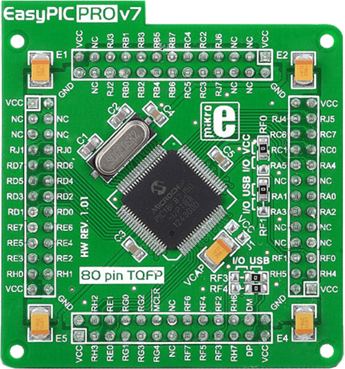
EasyPIC PRO v7a
Compiler
NECTO Studio
MCU
PIC18F87J50
Optimize various processes by closely monitoring temperature and humidity, minimizing risks and enhancing product quality.
A
A
Hardware Overview
How does it work?
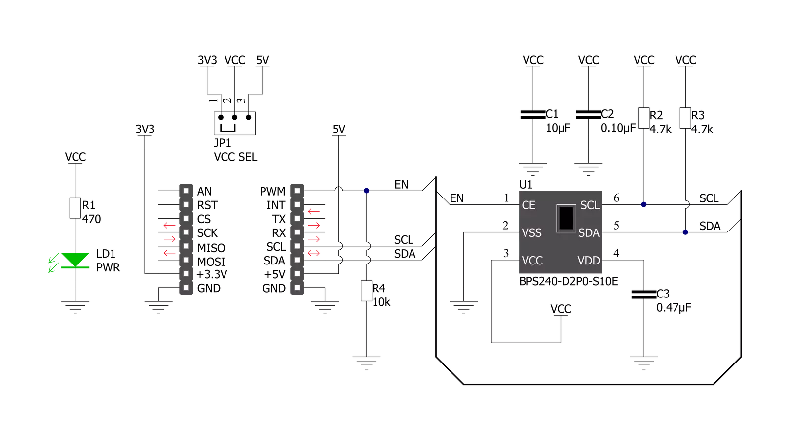
Temp&Hum 19 Click is based on the BPS240, relative humidity, and temperature sensor from Bourns. The BPS240 is based on innovative MEMS technology, which provides highly accurate condition readings. The humidity can be measured within a range of 0 to 100 %RH, while the temperature sensor is designed for a range of -30 to +100 °C. The enhanced features include a faster response time of less than one second with digital output and higher accuracy, with a typical RH accuracy of 2% in the measuring range of 20 up to 80 %RH at ambient temperature and ±0.3 °C for its operating temperature range with low
power consumption. Temp&Hum 19 Click communicates with MCU using the standard I2C 2-Wire interface to read data supporting Standard Mode operation with a clock frequency up to 100kHz, providing 10-bit data to the host controller. The output data is processed and compensated by the BPS240 sensor itself, requiring only basic conversion formulas to be applied within the firmware of the host controller. These conversion formulas are given in the BPS240 datasheet and directly provide readings in °C and %RH. This Click board™ also possesses an enabling function. The Enable pin is labeled as EN and routed to the
PWM pin of the mikroBUS™ socket, which activates and powers up the BPS240 (used for power ON/OFF purposes) and thus enables optimized power consumption. This Click board™ can operate with either 3.3V or 5V logic voltage levels selected via the VCC SEL jumper. This way, both 3.3V and 5V capable MCUs can use the communication lines properly. Also, this Click board™ comes equipped with a library containing easy-to-use functions and an example code that can be used as a reference for further development.

Features overview
Development board
EasyPIC PRO v7a is the seventh generation of PIC development boards specially designed to develop embedded applications rapidly. It supports a wide range of 8-bit PIC microcontrollers from Microchip and a broad set of unique functions, such as the first-ever embedded debugger/programmer over USB-C. The development board is well organized and designed so that the end-user has all the necessary elements, such as switches, buttons, indicators, connectors, and others, in one place. With two different connectors for each port, EasyPIC PRO v7a allows you to connect accessory boards, sensors, and custom electronics more efficiently than ever. Each part of the EasyPIC PRO
v7a development board contains the components necessary for the most efficient operation of the same board. In addition to the advanced integrated CODEGRIP programmer/debugger module, which offers many valuable programming/debugging options and seamless integration with the Mikroe software environment, the board also includes a clean and regulated power supply block for the development board. It can use a wide range of external power sources, including an external 12V power supply, 7-23V AC or 9-32V DC via DC connector/screw terminals, and a power source via the USB Type-C (USB-C) connector. Communication options such as USB-UART,
RS-232, and Ethernet are also included, including the well-established mikroBUS™ standard, two display options (graphical and character-based LCD), and a standard TQFP socket for the seventh-generation MCU cards. This socket covers a wide range of 8-bit PIC MCUs, from PIC18LF, PIC16LF, PIC16F, and PIC18F families. EasyPIC PRO v7a is an integral part of the Mikroe ecosystem for rapid development. Natively supported by Mikroe software tools, it covers many aspects of prototyping and development thanks to a considerable number of different Click boards™ (over a thousand boards), the number of which is growing every day.

Microcontroller Overview
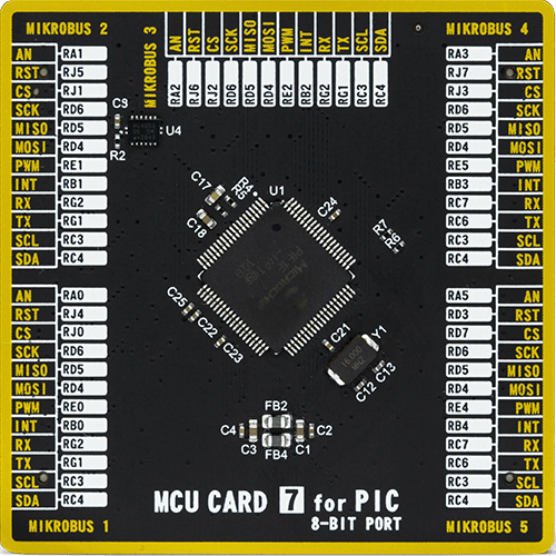
MCU Card / MCU
Type
7th Generation
Architecture
PIC
MCU Memory (KB)
128
Silicon Vendor
Microchip
Pin count
80
RAM (Bytes)
3904
Used MCU Pins
mikroBUS™ mapper
Take a closer look
Click board™ Schematic
Step by step
Project assembly

Start by selecting your development board and Click board™. Begin with the EasyPIC PRO v7a as your development board.


Software Support
Library Description
This library contains API for Temp&Hum 19 Click driver.
Key functions:
temphum19_restart_chip- This function restarts the chip by toggling the EN pin state.temphum19_set_mode_reg- This function programs the mode register with a desired mode value, and stores it to the ctx->detection_mode variable.temphum19_read_data- This function reads temperature and humidity raw data and converts them to Celsius and Percents respectfully.
Open Source
Code example
The complete application code and a ready-to-use project are available through the NECTO Studio Package Manager for direct installation in the NECTO Studio. The application code can also be found on the MIKROE GitHub account.
/*!
 * @file main.c
 * @brief TempHum19 Click example
 *
 * # Description
 * This example demonstrates the use of Temp & Hum 19 Click board by reading
 * the temperature and humidity data.
 *
 * The demo application is composed of two sections :
 *
 * ## Application Init
 * Initializes the driver and performs the Click default configuration.
 *
 * ## Application Task
 * Reads the temperature (Celsius) and humidity (Percents) data and displays the
 * results on the USB UART approximately once per second.
 *
 * @author Stefan Filipovic
 *
 */

#include "board.h"
#include "log.h"
#include "temphum19.h"

static temphum19_t temphum19;
static log_t logger;

void application_init ( void )
{
    log_cfg_t log_cfg;  /**< Logger config object. */
    temphum19_cfg_t temphum19_cfg;  /**< Click config object. */

    /**
     * Logger initialization.
     * Default baud rate: 115200
     * Default log level: LOG_LEVEL_DEBUG
     * @note If USB_UART_RX and USB_UART_TX
     * are defined as HAL_PIN_NC, you will
     * need to define them manually for log to work.
     * See @b LOG_MAP_USB_UART macro definition for detailed explanation.
     */
    LOG_MAP_USB_UART( log_cfg );
    log_init( &logger, &log_cfg );
    log_info( &logger, " Application Init " );

    // Click initialization.
    temphum19_cfg_setup( &temphum19_cfg );
    TEMPHUM19_MAP_MIKROBUS( temphum19_cfg, MIKROBUS_1 );

    if ( I2C_MASTER_ERROR == temphum19_init( &temphum19, &temphum19_cfg ) )
    {
        log_error( &logger, " Communication init." );
        for ( ; ; );
    }

    if ( TEMPHUM19_ERROR == temphum19_default_cfg ( &temphum19 ) )
    {
        log_error( &logger, " Default configuration." );
        for ( ; ; );
    }
    log_info( &logger, " Application Task " );
}

void application_task ( void )
{
    float temperature, humidity;
    if ( TEMPHUM19_OK == temphum19_read_data ( &temphum19, &temperature, &humidity ) )
    {
        log_printf ( &logger, " Temperature: %.1f C\r\n", temperature );
        log_printf ( &logger, " Humidity: %.2f %%\r\n\n", humidity );
        Delay_ms ( 1000 );
    }
}

int main ( void )
{
    /* Do not remove this line or clock might not be set correctly. */
    #ifdef PREINIT_SUPPORTED
    preinit();
    #endif

    application_init( );

    for ( ; ; )
    {
        application_task( );
    }

    return 0;
}

// ------------------------------------------------------------------------ END
Additional Support
Resources
Category:Temperature & humidity


