Unleash the potential of adaptive lighting control using SFH-5701 and STM32F107VCT6
Ambient light sensing: The key to comfort and convenience
Published Sep 22, 2023
Click board™
Ambient 7 Click
Dev. board
EasyMx PRO v7a for STM32
Compiler
NECTO Studio
MCU
STM32F107VCT6
From energy savings to personalized comfort, our ambient light intensity-sensing solution empowers you to take control of your lighting environment effortlessly
A
A
Hardware Overview
How does it work?
Ambient 7 Click is based on the SFH 5701 A01, an accurate light-intensity sensor from ams OSRAM. This sensor has many features that make it a perfect solution for small designs such as the Ambient 7 Click board™. One of these features is certainly its high level of integration, that allows a minimal number of external components, leaving room for an additional operational amplifier, labeled as OPA344, made by Texas Instruments, proven in many designs. As the SFH 5701 A01 limits the output current proportionaly to ambient light intensity, it creates an analog voltage on the R2 resistor (shunt). That voltage is directly proportional to the flowing current and thus the ambient light intensity. The previously mentioned operational amplifier serves as a unity gain
amplifier (buffer), to ensure good analog measurement signal integrity. The output of the unity gain amplifier is routed to the mikroBUS™ AN pin. The voltage on the AN pin can be measured by internal ADC integrated in the main MCU on the development board. The accuracy of SFH 5701 A01 sensor is not influenced by the light source type. It is calibrated so its spectral response is closely matched to a spectral response of the human eye. It is also worth to mention that the sensor qualification test plan is referenced to the guidelines of AEC-Q102 – a failure mechanism based stress test qualification for discrete optoelectronic semiconductors in automotive applications. Built in thermal compensation ensures that the measurement results are valid in
wide temperature range and thanks to integrated dark current suppression, the output signal while the sensor is exposed to dark environment is as minimal as possible. The sensor is operational in very wide Illuminance range – from 0.01lx up to 10000lx. In other words, it has linear response over 6 decades of illumination range. This Click board™ can be operated only with a 5V logic voltage level. The board must perform appropriate logic voltage level conversion before using MCUs with different logic levels. Also, it comes equipped with a library containing functions and an example code that can be used as a reference for further development.


Features overview
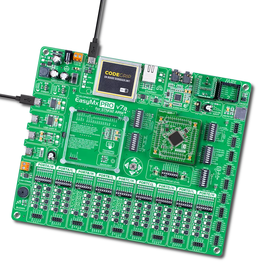
Development board
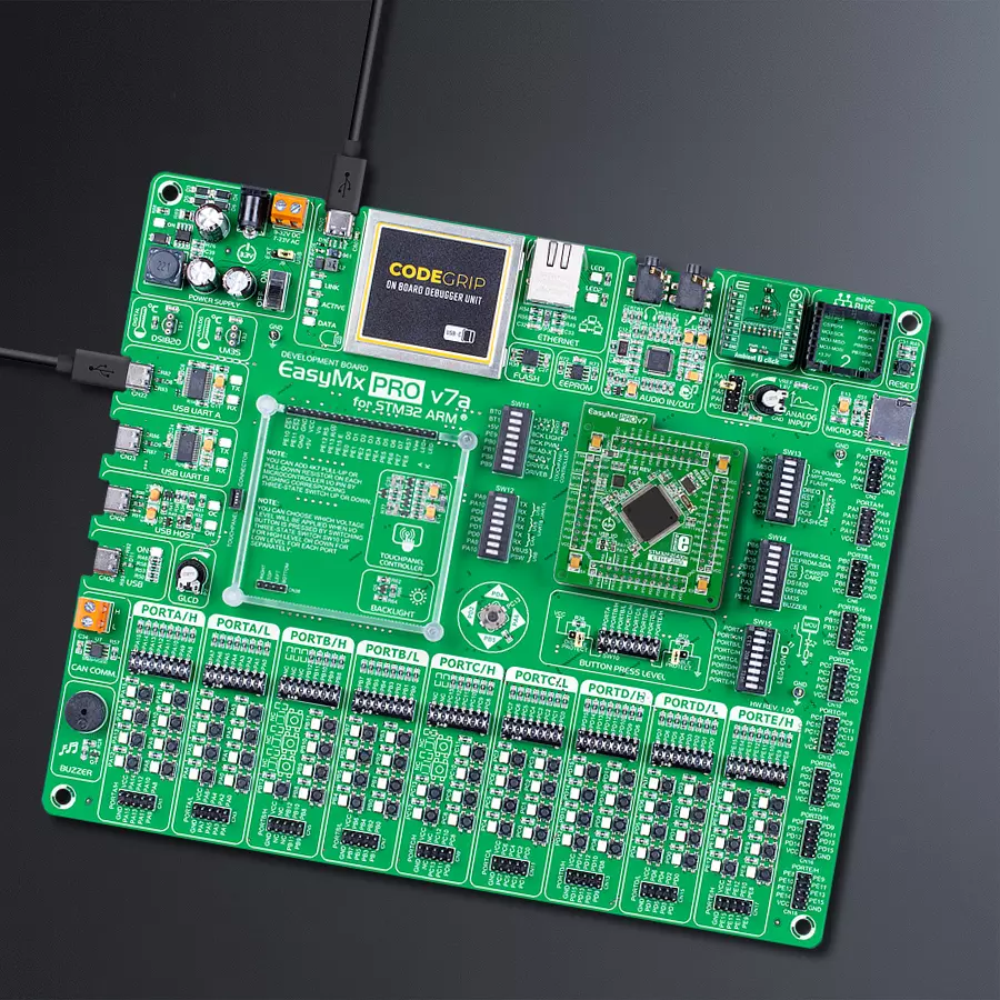
EasyMx PRO v7a for STM32 is the seventh generation of ARM development boards specially designed to develop embedded applications rapidly. It supports a wide range of 32-bit ARM microcontrollers from STMicroelectronics and a broad set of unique functions, such as the first-ever embedded debugger/programmer over USB-C. The development board is well organized and designed so that the end-user has all the necessary elements, such as switches, buttons, indicators, connectors, and others, in one place. With two different connectors for each port, EasyMx PRO v7afor STM32 allows you to connect accessory boards, sensors, and custom electronics more efficiently than ever. Each part of the EasyMx
PRO v7a for STM32 development board contains the components necessary for the most efficient operation of the same board. In addition to the advanced integrated CODEGRIP programmer/debugger module, which offers many valuable programming/debugging options and seamless integration with the Mikroe software environment, the board also includes a clean and regulated power supply block for the development board. It can use a wide range of external power sources, including an external 12V power supply, 7-23V AC or 9-32V DC via DC connector/screw terminals, and a power source via the USB Type-C (USB-C) connector. Communication options such as USB-UART, USB-HOST/DEVICE, CAN, and
Ethernet are also included, including the well-established mikroBUS™ standard, one display option for the TFT board line of products, and a standard TQFP socket for the seventh-generation MCU cards. This socket covers 32-bit ARM MCUs like STM32 Cortex-M3, -M7, and -M4 MCUs. EasyMx PRO v7afor STM32 is an integral part of the Mikroe ecosystem for rapid development. Natively supported by Mikroe software tools, it covers many aspects of prototyping and development thanks to a considerable number of different Click boards™ (over a thousand boards), the number of which is growing every day.

Microcontroller Overview
MCU Card / MCU
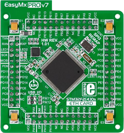
Type
7th Generation
Architecture
ARM Cortex-M3
MCU Memory (KB)
10
Silicon Vendor
STMicroelectronics
Pin count
100
RAM (Bytes)
100
Used MCU Pins
mikroBUS™ mapper
Take a closer look
Click board™ Schematic

Step by step
Project assembly

Start by selecting your development board and Click board™. Begin with the EasyMx PRO v7a for STM32 as your development board.


Track your results in real time
Application Output
1. Application Output - In Debug mode, the 'Application Output' window enables real-time data monitoring, offering direct insight into execution results. Ensure proper data display by configuring the environment correctly using the provided tutorial.

2. UART Terminal - Use the UART Terminal to monitor data transmission via a USB to UART converter, allowing direct communication between the Click board™ and your development system. Configure the baud rate and other serial settings according to your project's requirements to ensure proper functionality. For step-by-step setup instructions, refer to the provided tutorial.

3. Plot Output - The Plot feature offers a powerful way to visualize real-time sensor data, enabling trend analysis, debugging, and comparison of multiple data points. To set it up correctly, follow the provided tutorial, which includes a step-by-step example of using the Plot feature to display Click board™ readings. To use the Plot feature in your code, use the function: plot(*insert_graph_name*, variable_name);. This is a general format, and it is up to the user to replace 'insert_graph_name' with the actual graph name and 'variable_name' with the parameter to be displayed.

Software Support
Library Description
This library contains API for Ambient 7 Click driver.
Key functions:
ambient7_read_an_pin_value- This function reads results of AD conversion of the AN pinambient7_read_an_pin_voltage- This function reads results of AD conversion of the AN pin and converts them to proportional voltage level.
Open Source
Code example
The complete application code and a ready-to-use project are available through the NECTO Studio Package Manager for direct installation in the NECTO Studio. The application code can also be found on the MIKROE GitHub account.
/*!
 * @file
 * @brief Ambient7 Click example
 *
 * # Description
 * Reads the AN pin voltage.
 *
 * The demo application is composed of two sections :
 *
 * ## Application Init
 * Initializes ADC and LOG for logging data.
 *
 * ## Application Task
 * Reads the AN pin voltage and displays the results on the USB UART once per second.
 *
 * @note
 * Illuminance range [ EV ] - from 0.01 [ lx ] to 10k [ lx ]
 *
 * @author Luka Filipovic
 *
 */

#include "board.h"
#include "log.h"
#include "ambient7.h"

static ambient7_t ambient7;
static log_t logger;

void application_init ( void )
{
    log_cfg_t log_cfg;
    ambient7_cfg_t cfg;

    /**
     * Logger initialization.
     * Default baud rate: 115200
     * Default log level: LOG_LEVEL_DEBUG
     * @note If USB_UART_RX and USB_UART_TX
     * are defined as HAL_PIN_NC, you will
     * need to define them manually for log to work.
     * See @b LOG_MAP_USB_UART macro definition for detailed explanation.
     */
    LOG_MAP_USB_UART( log_cfg );
    log_init( &logger, &log_cfg );
    log_info( &logger, " Application Init " );

    // Click initialization.
    ambient7_cfg_setup( &cfg );
    AMBIENT7_MAP_MIKROBUS( cfg, MIKROBUS_1 );
    ambient7_init( &ambient7, &cfg );

    log_info( &logger, " Application Task " );
}

void application_task ( void )
{
    float voltage = 0;
    if ( AMBIENT7_OK == ambient7_read_an_pin_voltage ( &ambient7, &voltage ) )
    {
        log_printf( &logger, " AN Voltage : %.3f[V]\r\n\n", voltage );
        Delay_ms ( 1000 );
    }
}

int main ( void )
{
    /* Do not remove this line or clock might not be set correctly. */
    #ifdef PREINIT_SUPPORTED
    preinit();
    #endif

    application_init( );

    for ( ; ; )
    {
        application_task( );
    }

    return 0;
}

// ------------------------------------------------------------------------ END


