Achieve accurate ambient light detection and analysis with the TCS3530 and STM32F207VGT6
True color ambient light sensor with selective flicker detection

Published Aug 27, 2024
Click board™
Color 18 Click
Dev. board
EasyMx PRO v7a for STM32
Compiler
NECTO Studio
MCU
STM32F207VGT6
Determine the type of light source (incandescent, fluorescent, LED) for adaptive lighting control
A
A
Hardware Overview
How does it work?
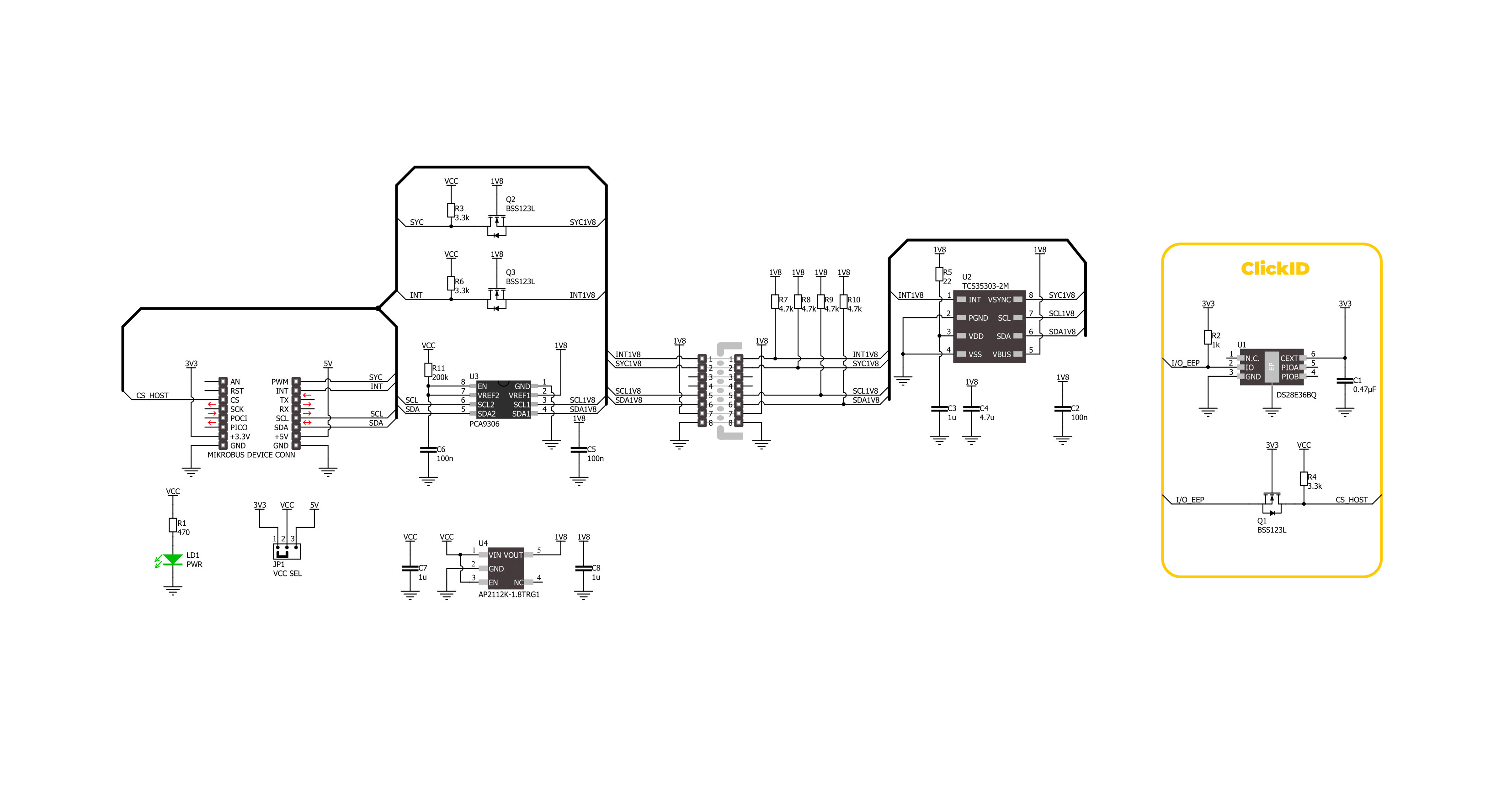
Color 18 Click is based on the TCS3530, a true color ambient light sensor from ams OSRAM. This sensor has advanced capabilities such as true color XYZ ambient light detection and selective flicker detection, supporting frequencies up to 7kHz. It is fully embedded, with an integrated aperture and diffuser, ensuring precise pre-calibration by maintaining accurate distances between the photodiodes and other optical elements. This sophisticated design allows the sensor to provide eight concurrent ambient light sensing channels, each with an independent gain configuration, which can be linked to any of the 27 photodiodes. Additionally, the built-in sequencer makes automated measurements, eliminating the need for re-programming after each cycle. The sensor's UV/IR blocking filter enhances its ability to measure ambient light accurately and calculate key parameters such as illuminance, chromaticity, and correlated color temperature (CCT) for optimal display management. Moreover, the TCS3530 on the Color 18 Click offers direct ambient light flicker detection, capable of handling both traditional 50Hz/60Hz AC light sources and modern LED lighting systems with PDM control. This flicker detection operates in tandem with ambient light sensing, with its gain settings managed independently, and allows for external flicker
frequency calculations on a host MCU. Based on these features, this Click board™ makes an excellent choice for precise lighting management and display optimization like calculating CCT and chromaticity, supporting auto white balancing, identifying light types, and ensuring flicker-free camera operation. This Click board™ is designed in a unique format supporting the newly introduced MIKROE feature called "Click Snap." Unlike the standardized version of Click boards, this feature allows the main sensor area to become movable by breaking the PCB, opening up many new possibilities for implementation. Thanks to the Snap feature, the switches can operate autonomously by accessing their signals directly on the pins marked 1-8. Additionally, the Snap part includes a specified and fixed screw hole position, enabling users to secure the Snap board in their desired location. This Click board™ uses a standard 2-wire I2C interface to communicate with the host MCU, supporting Standard mode with up to 400kHz of frequency clock. The I2C interface and registers allow for controlling various sensor functions, such as offset and measurement mode settings, interrupt system management for interrupt signals available on the INT pin, and adjusting offset and threshold values for color sensor data. This flexibility ensures precise and customizable operations tailored to
specific application needs. The SYC pin on the mikroBUS™ socket serves a dual-purpose function. It can be used as a synchronization input, allowing the sensor to align its measurements with external events or signals, ensuring accurate timing and coordination in applications that require precise synchronization. Alternatively, it can also function as a general-purpose open-drain input/output pin, providing additional flexibility for various control or signaling tasks, depending on the application's specific requirements. The TCS3530 does not require a specific Power-Up sequence but requires a voltage of 1.8V for its interface and logic part to work correctly. Therefore, a small regulating LDO, the AP2112, provides a 1.8V out of selected mikroBUS™ power rail. Since the sensor operates on 1.8V, this Click board™ also features the PCA9306 voltage-level translator, allowing the TCS3530 to work properly with 3.3V and 5V MCU. This Click board™ can operate with either 3.3V or 5V logic voltage levels selected via the VCC SEL jumper. This way, both 3.3V and 5V capable MCUs can use the communication lines properly. Also, this Click board™ comes equipped with a library containing easy-to-use functions and an example code that can be used as a reference for further development.

Features overview
Development board
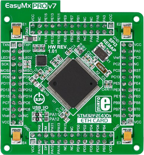
EasyMx PRO v7a for STM32 is the seventh generation of ARM development boards specially designed to develop embedded applications rapidly. It supports a wide range of 32-bit ARM microcontrollers from STMicroelectronics and a broad set of unique functions, such as the first-ever embedded debugger/programmer over USB-C. The development board is well organized and designed so that the end-user has all the necessary elements, such as switches, buttons, indicators, connectors, and others, in one place. With two different connectors for each port, EasyMx PRO v7afor STM32 allows you to connect accessory boards, sensors, and custom electronics more efficiently than ever. Each part of the EasyMx
PRO v7a for STM32 development board contains the components necessary for the most efficient operation of the same board. In addition to the advanced integrated CODEGRIP programmer/debugger module, which offers many valuable programming/debugging options and seamless integration with the Mikroe software environment, the board also includes a clean and regulated power supply block for the development board. It can use a wide range of external power sources, including an external 12V power supply, 7-23V AC or 9-32V DC via DC connector/screw terminals, and a power source via the USB Type-C (USB-C) connector. Communication options such as USB-UART, USB-HOST/DEVICE, CAN, and
Ethernet are also included, including the well-established mikroBUS™ standard, one display option for the TFT board line of products, and a standard TQFP socket for the seventh-generation MCU cards. This socket covers 32-bit ARM MCUs like STM32 Cortex-M3, -M7, and -M4 MCUs. EasyMx PRO v7afor STM32 is an integral part of the Mikroe ecosystem for rapid development. Natively supported by Mikroe software tools, it covers many aspects of prototyping and development thanks to a considerable number of different Click boards™ (over a thousand boards), the number of which is growing every day.

Microcontroller Overview
MCU Card / MCU
Type
7th Generation
Architecture
ARM Cortex-M3
MCU Memory (KB)
10
Silicon Vendor
STMicroelectronics
Pin count
100
RAM (Bytes)
100
Used MCU Pins
mikroBUS™ mapper
Take a closer look
Click board™ Schematic
Step by step
Project assembly

Start by selecting your development board and Click board™. Begin with the EasyMx PRO v7a for STM32 as your development board.


Software Support
Library Description
This library contains API for Color 18 Click driver.
Key functions:
color18_get_int_pin- This function returns the INT pin logic state.color18_read_data- This function checks if the color measurement data are ready for all channels and reads them.color18_clear_fifo- This function clears the FIFO buffers and interrupts.
Open Source
Code example
The complete application code and a ready-to-use project are available through the NECTO Studio Package Manager for direct installation in the NECTO Studio. The application code can also be found on the MIKROE GitHub account.
/*!
 * @file main.c
 * @brief Color 18 Click example
 *
 * # Description
 * This example demonstrates the use of Color 18 Click by reading and displaying
 * the values from all 8 modulator channels.
 *
 * The demo application is composed of two sections :
 *
 * ## Application Init
 * Initializes the driver and performs the Click default configuration.
 *
 * ## Application Task
 * Waits for a data ready interrupt then reads data from all 8 modulator channels
 * and displays the results on the USB UART every 200ms approximately.
 *
 * @author Stefan Filipovic
 *
 */

#include "board.h"
#include "log.h"
#include "color18.h"

static color18_t color18;
static log_t logger;

void application_init ( void )
{
    log_cfg_t log_cfg;  /**< Logger config object. */
    color18_cfg_t color18_cfg;  /**< Click config object. */

    /**
     * Logger initialization.
     * Default baud rate: 115200
     * Default log level: LOG_LEVEL_DEBUG
     * @note If USB_UART_RX and USB_UART_TX
     * are defined as HAL_PIN_NC, you will
     * need to define them manually for log to work.
     * See @b LOG_MAP_USB_UART macro definition for detailed explanation.
     */
    LOG_MAP_USB_UART( log_cfg );
    log_init( &logger, &log_cfg );
    log_info( &logger, " Application Init " );

    // Click initialization.
    color18_cfg_setup( &color18_cfg );
    COLOR18_MAP_MIKROBUS( color18_cfg, MIKROBUS_1 );
    if ( I2C_MASTER_ERROR == color18_init( &color18, &color18_cfg ) )
    {
        log_error( &logger, " Communication init." );
        for ( ; ; );
    }

    if ( COLOR18_ERROR == color18_default_cfg ( &color18 ) )
    {
        log_error( &logger, " Default configuration." );
        for ( ; ; );
    }

    log_info( &logger, " Application Task " );
}

void application_task ( void )
{
    color18_data_t color_data;

    // Wait for a data ready interrupt
    while ( color18_get_int_pin ( &color18 ) );

    if ( COLOR18_OK == color18_read_data ( &color18, &color_data ) )
    {
        log_printf ( &logger, "X: %u\r\n", color_data.x );
        log_printf ( &logger, "Y: %u\r\n", color_data.y );
        log_printf ( &logger, "Z: %u\r\n", color_data.z );
        log_printf ( &logger, "IR: %u\r\n", color_data.ir );
        log_printf ( &logger, "HgL: %u\r\n", color_data.hgl );
        log_printf ( &logger, "HgH: %u\r\n", color_data.hgh );
        log_printf ( &logger, "Clear: %u\r\n", color_data.clear );
        log_printf ( &logger, "Flicker: %u\r\n\n", color_data.flicker );
    }
}

int main ( void )
{
    /* Do not remove this line or clock might not be set correctly. */
    #ifdef PREINIT_SUPPORTED
    preinit();
    #endif

    application_init( );

    for ( ; ; )
    {
        application_task( );
    }

    return 0;
}

// ------------------------------------------------------------------------ END
Additional Support
Resources
Category:Optical


