Achieve some serious voltage step-down brilliance with MPQ8632 and TM4C123GH6PZL
Synchronous step-down magic!

Published Aug 01, 2023
Click board™
Buck 12 Click
Dev. board
EasyMx PRO v7 for Tiva
Compiler
NECTO Studio
MCU
TM4C123GH6PZL
Compact and versatile, our buck step-down converter is essential in portable devices, extending battery life and enhancing usability
A
A
Hardware Overview
How does it work?
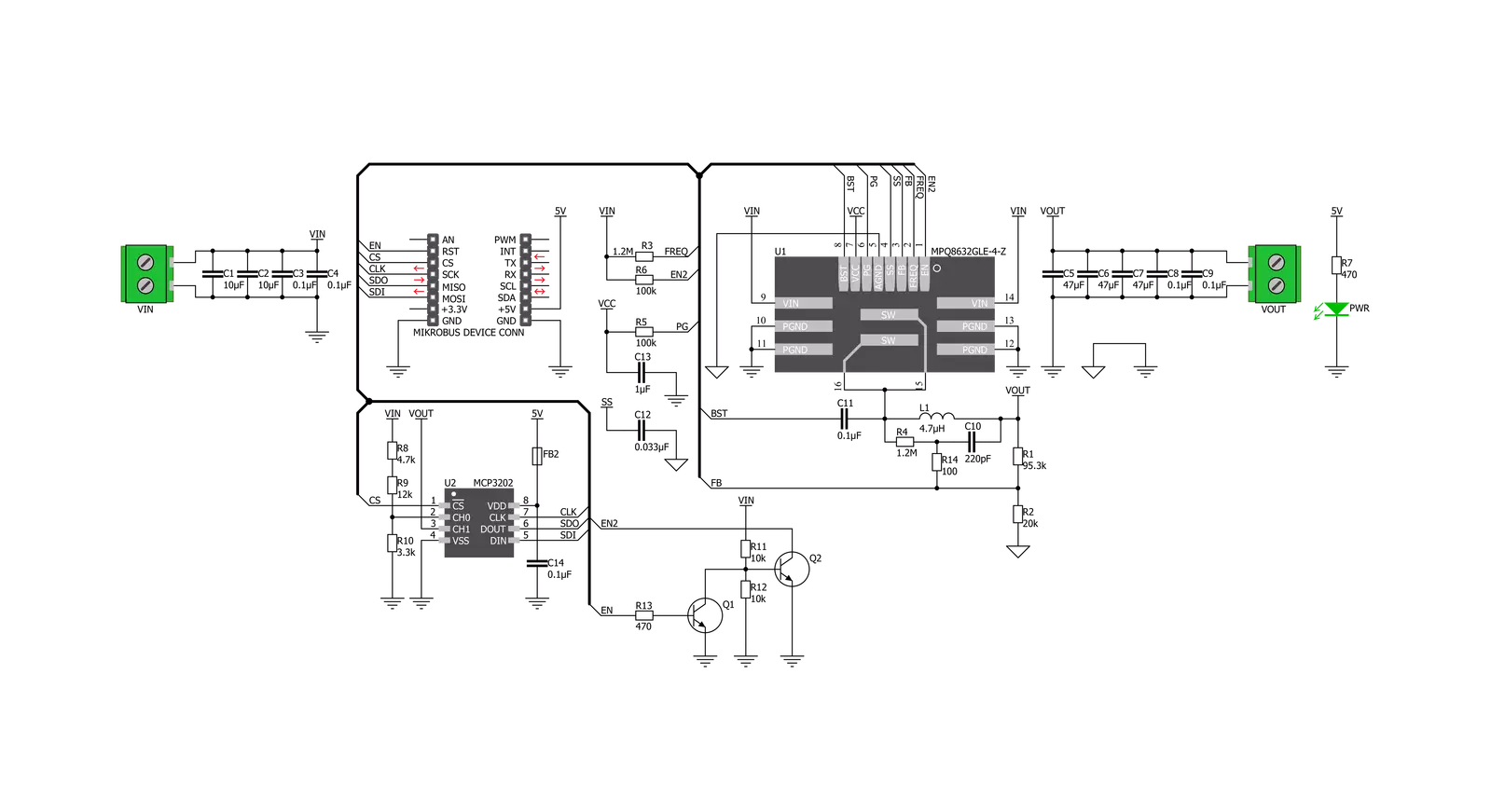
Buck 12 Click is based on the MPQ8632, a synchronous step-down converter from Monolithic Power Systems (MPS). This advanced integrated step-down converter requires a minimum number of external components readily available on the market. It utilizes a peak-current-mode control architecture, ensuring good efficiency and automatic switch-mode switching. The MPQ8632 buck converter features over-current, under-voltage, and thermal protection, making Buck 12 click a robust and reliable power supply solution. The feedback voltage on the FB pin determines the output voltage. The output voltage is set to 3.3V, making it usable with most embedded applications, allowing them to be powered from the same source, like the rest of the application, which may use a higher voltage for its operation. This is a common-case scenario in various field applications requiring a relatively high voltage, i.e., for servos, step motors, displays, and more. When there is an overload at the output, the low-side MOSFET will allow the inductor current to drop.
It will remain open until the current through the inductor falls below the limit. Suppose the FB voltage drops too much during the overload. In that case, the device enters the hiccup mode, which turns off the output power stage, discharges the soft-start capacitor, and automatically retries the soft-start. The MPQ8632 can automatically switch between different operating modes, depending on the current through the load. At very light loads, the device is operated in skip mode. In this mode, HS-FET turns on for a fixed interval determined by the one-shot on-timer. When the HS-FET turns off, the LS-FET turns on until the inductor current reaches zero. The LS-FET driver turns into a tri-state (high Z) whenever the inductor current reaches zero. This way, the device is idle while the light load consumes energy stored within the coil. This greatly improves the efficiency when a light load is used. This is also called discontinuous conduction mode (DCM). The MPQ8632 automatically switches to heavy load operation or continuous
conduction mode (CCM) when heavily loaded. In this mode, when VFB is below VREF, HS-FET turns on for a fixed interval determined by the one-shot on-timer. When the HS-FET turns off, the LS-FET turns on until the next period. In CCM operation, the switching frequency is fairly constant and called PWM mode. Packed in QFN casing (3X4mm), the MPQ8632 occupies a small area on the PCB. Combined with the low count of external components it requires, the MPQ8632 leaves enough space for an additional IC to be used. This click uses the MCP3202, a Dual Channel 12-Bit A/D Converter which uses the SPI interface from Microchip. It allows monitoring of the input and output voltages over the SPI interface. This ADC is powered by the +5V mikroBUS™ power rail. The same voltage is used as a reference. The Click board™ itself requires an external power supply to be connected at the input terminal, labeled as VIN. The VOUT terminal provides the connected load with the regulated 3.3V voltage.

Features overview
Development board
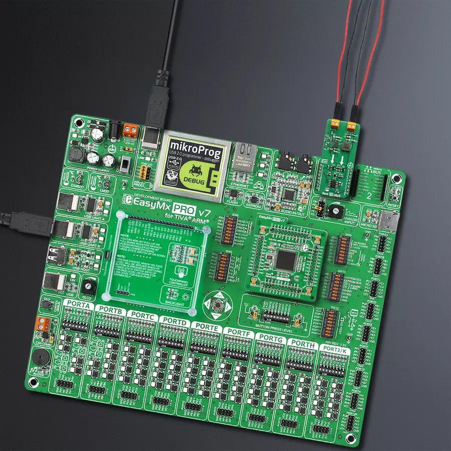
EasyMx PRO v7 for TIVA is the seventh generation of ARM development boards specially designed for the needs of rapid development of embedded applications. It supports a wide range of 32-bit ARM microcontrollers from Texas Instruments and a broad set of unique functions, such as a powerful onboard mikroProg programmer and In-Circuit debugger over USB-B. The development board is well organized and designed so that the end-user has all the necessary elements, such as switches, buttons, indicators, connectors, and others, in one place. With two different connectors for each port, EasyMx PRO v7 for TIVA allows you to connect accessory boards, sensors, and custom electronics more efficiently than ever. Each part of the EasyMx
PRO v7 for TIVA development board contains the components necessary for the most efficient operation of the same board. An integrated mikroProg, a fast USB 2.0 programmer with mikroICD hardware In-Circuit Debugger, offers many valuable programming/debugging options and seamless integration with the Mikroe software environment. Besides it also includes a clean and regulated power supply block for the development board. It can use a wide range of external power sources, including an external 12V power supply, 7-23V AC or 9-32V DC via DC connector/screw terminals, and a power source via the USB Type-B (USB-B) connector. Communication options such as USB-UART, USB-HOST/DEVICE, CAN, and
Ethernet are also included, including the well-established mikroBUS™ standard, one display option for the TFT board line of products, and a standard TQFP socket for the seventh-generation MCU cards. This socket covers a wide range of 32-bit TIVA-series ARM Cortex-M4 MCUs. EasyMx PRO v7 for TIVA is an integral part of the Mikroe ecosystem for rapid development. Natively supported by Mikroe software tools, it covers many aspects of prototyping and development thanks to a considerable number of different Click boards™ (over a thousand boards), the number of which is growing every day.

Microcontroller Overview
MCU Card / MCU
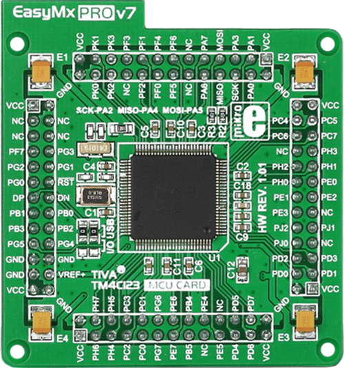
Type
7th Generation
Architecture
ARM Cortex-M4
MCU Memory (KB)
10
Silicon Vendor
Texas Instruments
Pin count
100
RAM (Bytes)
100
Used MCU Pins
mikroBUS™ mapper
Take a closer look
Click board™ Schematic
Step by step
Project assembly

Start by selecting your development board and Click board™. Begin with the EasyMx PRO v7 for Tiva as your development board.


Software Support
Library Description
This library contains API for Buck 12 Click driver.
Key functions:
buck12_control- This function for enable or disable devicebuck12_get_channel_adc- This function reads ADC on the channelbuck12_get_voltage- This function gets voltage
Open Source
Code example
The complete application code and a ready-to-use project are available through the NECTO Studio Package Manager for direct installation in the NECTO Studio. The application code can also be found on the MIKROE GitHub account.
/*!
 * \file
 * \brief Buck12 Click example
 *
 * # Description
 * This demo application reads the voltage in [mV] at the input and output terminals.
 *
 * The demo application is composed of two sections :
 *
 * ## Application Init
 * Configuring Clicks and log objects.
 *
 * ## Application Task
 * Reads the voltage in [mV] at the input and output terminals.
 * This data logs to the USBUART every 2 sec.
 *
 * \author MikroE Team
 *
 */
// ------------------------------------------------------------------- INCLUDES

#include "board.h"
#include "log.h"
#include "buck12.h"

// ------------------------------------------------------------------ VARIABLES

static buck12_t buck12;
static log_t logger;

// ------------------------------------------------------ APPLICATION FUNCTIONS

void application_init ( void )
{
    log_cfg_t log_cfg;
    buck12_cfg_t cfg;

    /**
     * Logger initialization.
     * Default baud rate: 115200
     * Default log level: LOG_LEVEL_DEBUG
     * @note If USB_UART_RX and USB_UART_TX
     * are defined as HAL_PIN_NC, you will
     * need to define them manually for log to work.
     * See @b LOG_MAP_USB_UART macro definition for detailed explanation.
     */
    LOG_MAP_USB_UART( log_cfg );
    log_init( &logger, &log_cfg );
    log_info( &logger, "---- Application Init ----" );

    //  Click initialization.

    buck12_cfg_setup( &cfg );
    BUCK12_MAP_MIKROBUS( cfg, MIKROBUS_1 );
    buck12_init( &buck12, &cfg );

    buck12_control( &buck12, BUCK12_ENABLE );
    Delay_ms ( 1000 );
    Delay_ms ( 1000 );
}

void application_task ( void )
{
    float voltage;

    voltage = buck12_get_voltage( &buck12, BUCK12_INPUT_VOLTAGE );

    log_printf( &logger, "* Vin : %f mV \r\n ", voltage);
    voltage = buck12_get_voltage( &buck12, BUCK12_OUTPUT_VOLTAGE );

    log_printf( &logger, "* Vout : %f mV \r\n ", voltage);
    log_printf( &logger, "--------------------------\r\n");
    Delay_ms ( 1000 );
    Delay_ms ( 1000 );
}

int main ( void )
{
    /* Do not remove this line or clock might not be set correctly. */
    #ifdef PREINIT_SUPPORTED
    preinit();
    #endif

    application_init( );

    for ( ; ; )
    {
        application_task( );
    }

    return 0;
}

// ------------------------------------------------------------------------ END
Additional Support
Resources
Category:Buck


