使用MIC1557和PIC32MZ1024EFH064构建一个可靠的定时系统
确保您的电路永远不会失调

已发布 6月 24, 2024
点击板
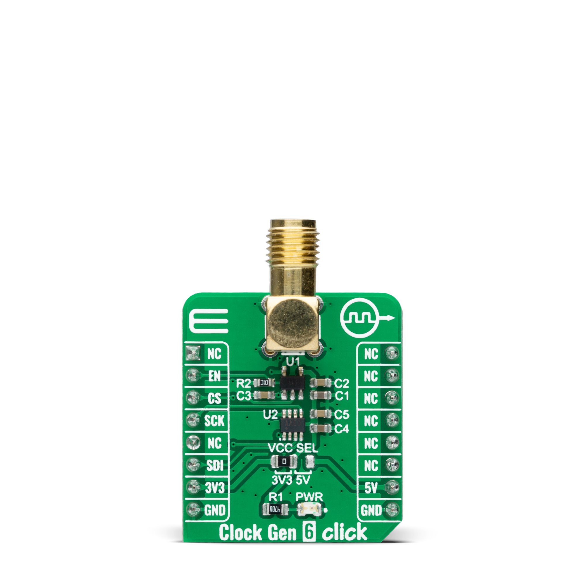
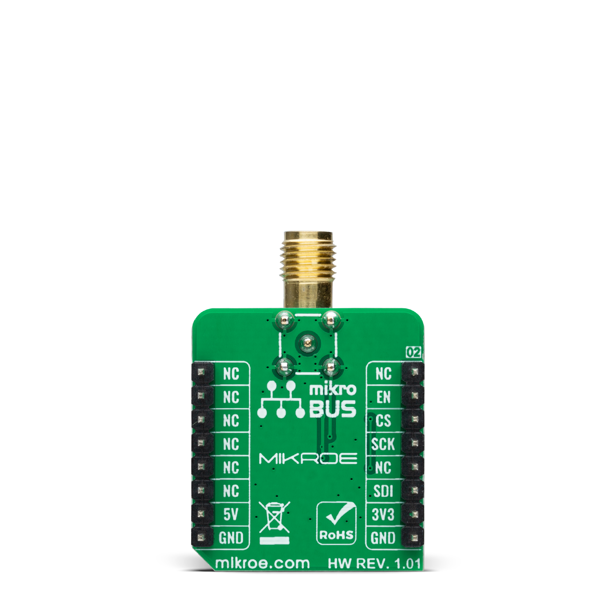
Clock Gen 6 Click
开发板
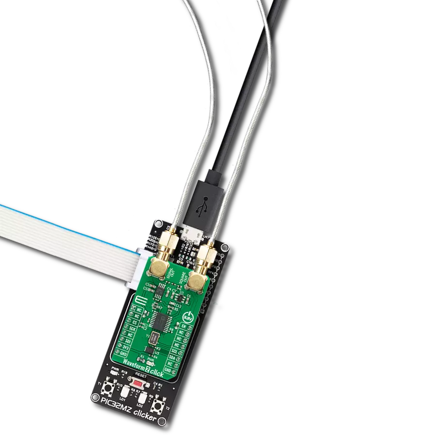
PIC32MZ clicker
编译器
NECTO Studio
微控制器单元
PIC32MZ1024EFH064
IttyBitty CMOS RC振荡器设计用于提供轨到轨脉冲,以实现精确的时间延迟或频率生成。
A
A
硬件概览
它是如何工作的?
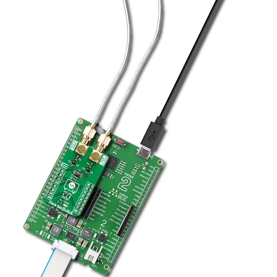
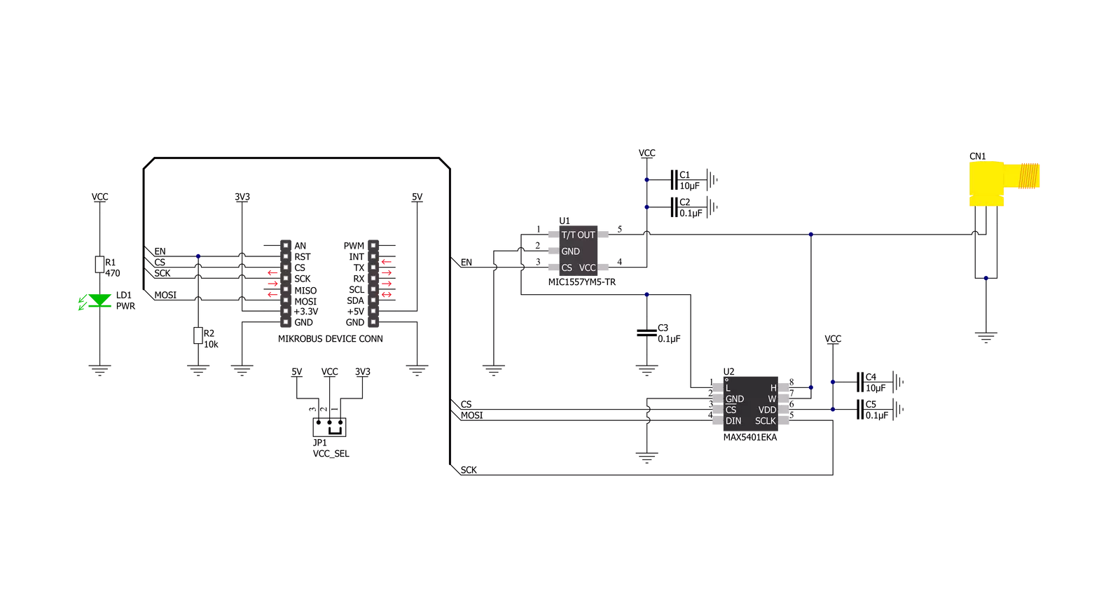
Clock Gen 6 Click基于MIC1557,是一种低功耗数字频率解决方案,提供用于创建简单RC振荡器电路的逻辑,由Microchip Technology提供。MIC1557提供轨到轨脉冲,以实现精确的频率生成,并具有单一阈值和触发连接,内部连接,用于仅具有可编程输出频率和启用/复位控制信号的无稳(振荡器)操作,旨在作为具有关断功能的振荡器。如前所述,无稳态振荡器在两个状态(开和关)之间切换,产生连续方波。通过将两个比较器输入、阈值和触发引脚(THR和TRG)连接在一起,形成一个T/T
引脚,MIC1557针对这一功能进行了优化。外部电容通过外部电阻(形式为数字电位计)缓慢充电,用户可以通过它跨过频率范围,从而调整所需的输出。用数字电位计替换电阻允许用户编程频率输出,如在此Click板™上执行的那样。为此,使用了与MCU通过3线SPI串行接口通信的数字电位计MAX5401,用于设置MIC1557 OUT线上的电阻,调整频率高达5MHz。除了SPI通信,此Click板™还使用一个附加引脚。EN引脚,标记为EN并路由到mikroBUS™插座的RST引脚,用于优化功耗并用于电源开/关
目的(控制振荡器内部电路的偏置电源)。当MIC1557未被选中时,电源电流小于1μA,设备处于关断状态。将EN引脚强制为低电平会通过设置触发器重置设备,使输出处于低逻辑状态。此Click板™可以选择3.3V或5V逻辑电压电平,通过VCC SEL跳线选择。这种方式下,3.3V和5V兼容的MCU都可以正确使用通信线。然而,此Click板™配备了包含易于使用的功能和示例代码的库,可以用作进一步开发的参考。
功能概述
开发板
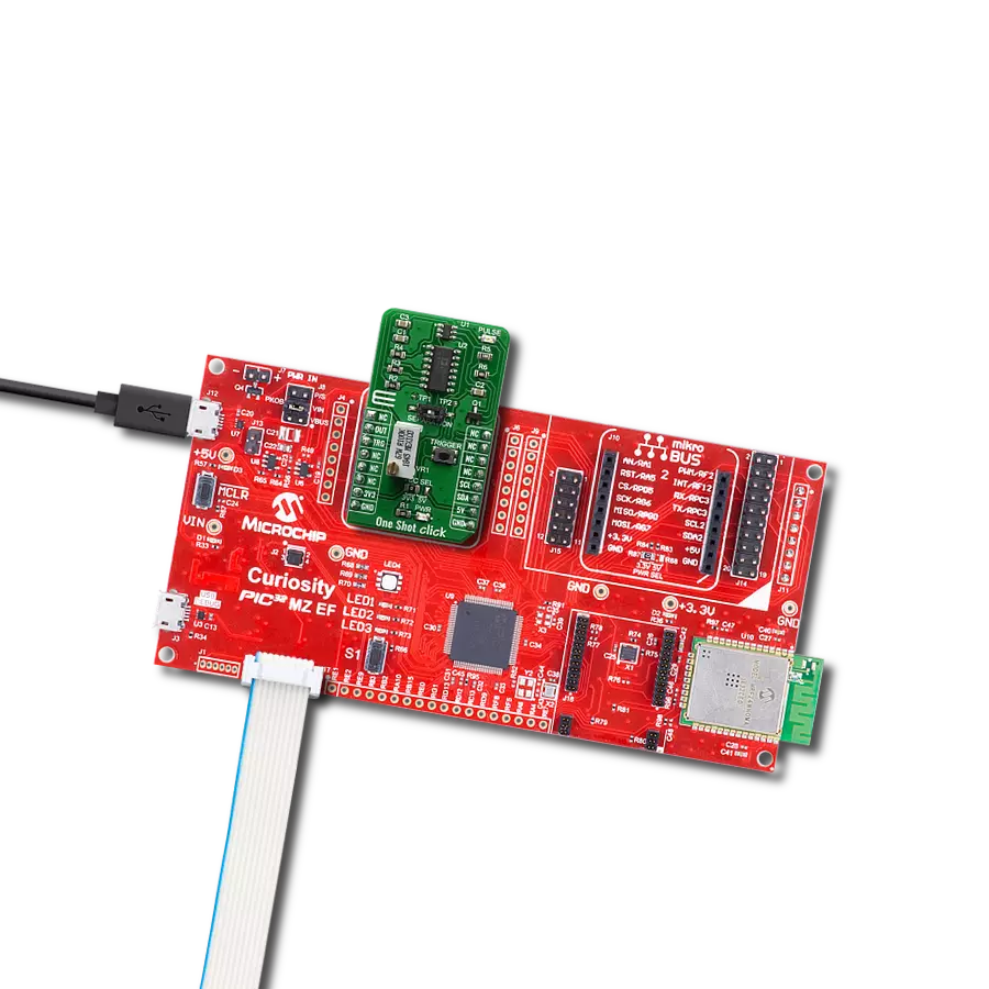
PIC32MZ Clicker 是一款紧凑型入门开发板,它将 Click 板™的灵活性带给您喜爱的微控制器,使其成为实现您想法的完美入门套件。它配备了一款板载 32 位带有浮点单元的 Microchip PIC32MZ 微控制器,一个 USB 连接器,LED 指示灯,按钮,一个 mikroProg 连接器,以及一个用于与外部电子设备接口的头部。得益于其紧凑的设计和清晰易识别的丝网标记,它提供了流畅且沉浸式的工作体验,允许在任
何情况下、任何地方都能访问。PIC32MZ Clicker 开 发套件的每个部分都包含了使同一板块运行最高效的必要组件。除了可以选择 PIC32MZ Clicker 的编程方式,使用 USB HID mikroBootloader 或通过外部 mikroProg 连接器为 PIC,dsPIC 或 PIC32 编程外,Clicker 板还包括一个干净且调节过的开发套件电源供应模块。USB Micro-B 连接可以提供多达 500mA 的电流,这足以操作所有板载和附加模块。所有
mikroBUS™ 本身支持的通信方法都在这块板上,包 括已经建立良好的 mikroBUS™ 插槽、重置按钮以及若干按钮和 LED 指示灯。PIC32MZ Clicker 是 Mikroe 生态系统的一个组成部分,允许您在几分钟内创建新的应用程序。它由 Mikroe 软件工具原生支持,得益于大量不同的 Click 板™(超过一千块板),其数量每天都在增长,它涵盖了原型制作的许多方面。

微控制器概述
MCU卡片 / MCU

建筑
PIC32
MCU 内存 (KB)
1024
硅供应商
Microchip
引脚数
64
RAM (字节)
524288
使用的MCU引脚
mikroBUS™映射器
“仔细看看!”
Click board™ 原理图
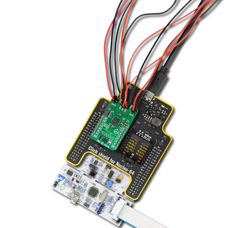
一步一步来
项目组装

从选择您的开发板和Click板™开始。以PIC32MZ clicker作为您的开发板开始。


软件支持
库描述
该库包含 Clock Gen 6 Click 驱动程序的 API。
关键功能:
clockgen6_set_digipot- 此函数通过使用SPI串行接口设置数字电位计位置。clockgen6_enable_output- 此函数通过将EN引脚设置为高逻辑状态来启用输出。clockgen6_disable_output- 此函数通过将EN引脚设置为低逻辑状态来禁用输出。
开源
代码示例
完整的应用程序代码和一个现成的项目可以通过NECTO Studio包管理器直接安装到NECTO Studio。 应用程序代码也可以在MIKROE的GitHub账户中找到。
/*!
 * @file main.c
 * @brief Clock Gen 6 Click Example.
 *
 * # Description
 * This example demonstrates the use of Clock Gen 6 Click board which acts as
 * an astable oscillator.
 *
 * The demo application is composed of two sections :
 *
 * ## Application Init
 * Initializes the driver and performs the Click default configuration which sets the digital
 * potentiometer to max position and enables the clock output.
 *
 * ## Application Task
 * Changes the clock output frequency by changing the digital potentiometer position every second.
 * The potentiometer position value will be displayed on the USB UART.
 *
 * @author Stefan Filipovic
 *
 */

#include "board.h"
#include "log.h"
#include "clockgen6.h"

static clockgen6_t clockgen6;   /**< Clock Gen 6 Click driver object. */
static log_t logger;    /**< Logger object. */

void application_init ( void )
{
    log_cfg_t log_cfg;  /**< Logger config object. */
    clockgen6_cfg_t clockgen6_cfg;  /**< Click config object. */

    /**
     * Logger initialization.
     * Default baud rate: 115200
     * Default log level: LOG_LEVEL_DEBUG
     * @note If USB_UART_RX and USB_UART_TX
     * are defined as HAL_PIN_NC, you will
     * need to define them manually for log to work.
     * See @b LOG_MAP_USB_UART macro definition for detailed explanation.
     */
    LOG_MAP_USB_UART( log_cfg );
    log_init( &logger, &log_cfg );
    log_info( &logger, " Application Init " );

    // Click initialization.
    clockgen6_cfg_setup( &clockgen6_cfg );
    CLOCKGEN6_MAP_MIKROBUS( clockgen6_cfg, MIKROBUS_1 );
    if ( DIGITAL_OUT_UNSUPPORTED_PIN == clockgen6_init( &clockgen6, &clockgen6_cfg ) )
    {
        log_error( &logger, " Communication init." );
        for ( ; ; );
    }

    if ( CLOCKGEN6_ERROR == clockgen6_default_cfg ( &clockgen6 ) )
    {
        log_error( &logger, " Default configuration." );
        for ( ; ; );
    }

    log_info( &logger, " Application Task " );
}

void application_task ( void )
{
    for ( int16_t pos = CLOCKGEN6_DIGIPOT_POSITION_MAX; pos >= CLOCKGEN6_DIGIPOT_POSITION_MIN; )
    {
        if ( CLOCKGEN6_OK == clockgen6_set_digipot ( &clockgen6, pos ) )
        {
            log_printf( &logger, " DIGIPOT position: %u\r\n", pos );
            Delay_ms ( 1000 );
            pos -= 5;
        }
    }
}

int main ( void )
{
    /* Do not remove this line or clock might not be set correctly. */
    #ifdef PREINIT_SUPPORTED
    preinit();
    #endif

    application_init( );

    for ( ; ; )
    {
        application_task( );
    }

    return 0;
}

// ------------------------------------------------------------------------ END