使用ACS70331和STM32L496AG实时洞察电流行为
通往可靠电流洞察的路径
已发布 7月 22, 2025
点击板
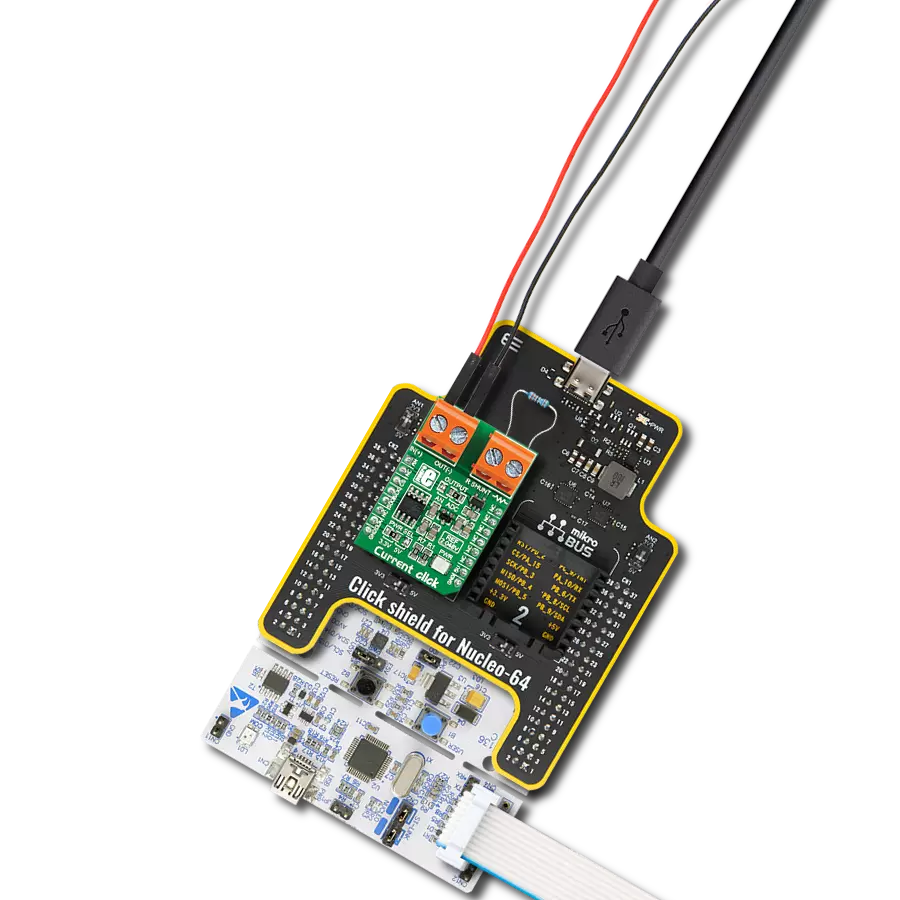
Current 4 Click
开发板
Discovery kit with STM32L496AG MCU
编译器
NECTO Studio
微控制器单元
STM32L496AG
通过利用我们的电流测量解决方案来实现运营卓越,以跟踪电流变化,使您能够基于数据做出决策,从而提高效率并减少停机时间。
A
A
硬件概览
它是如何工作的?
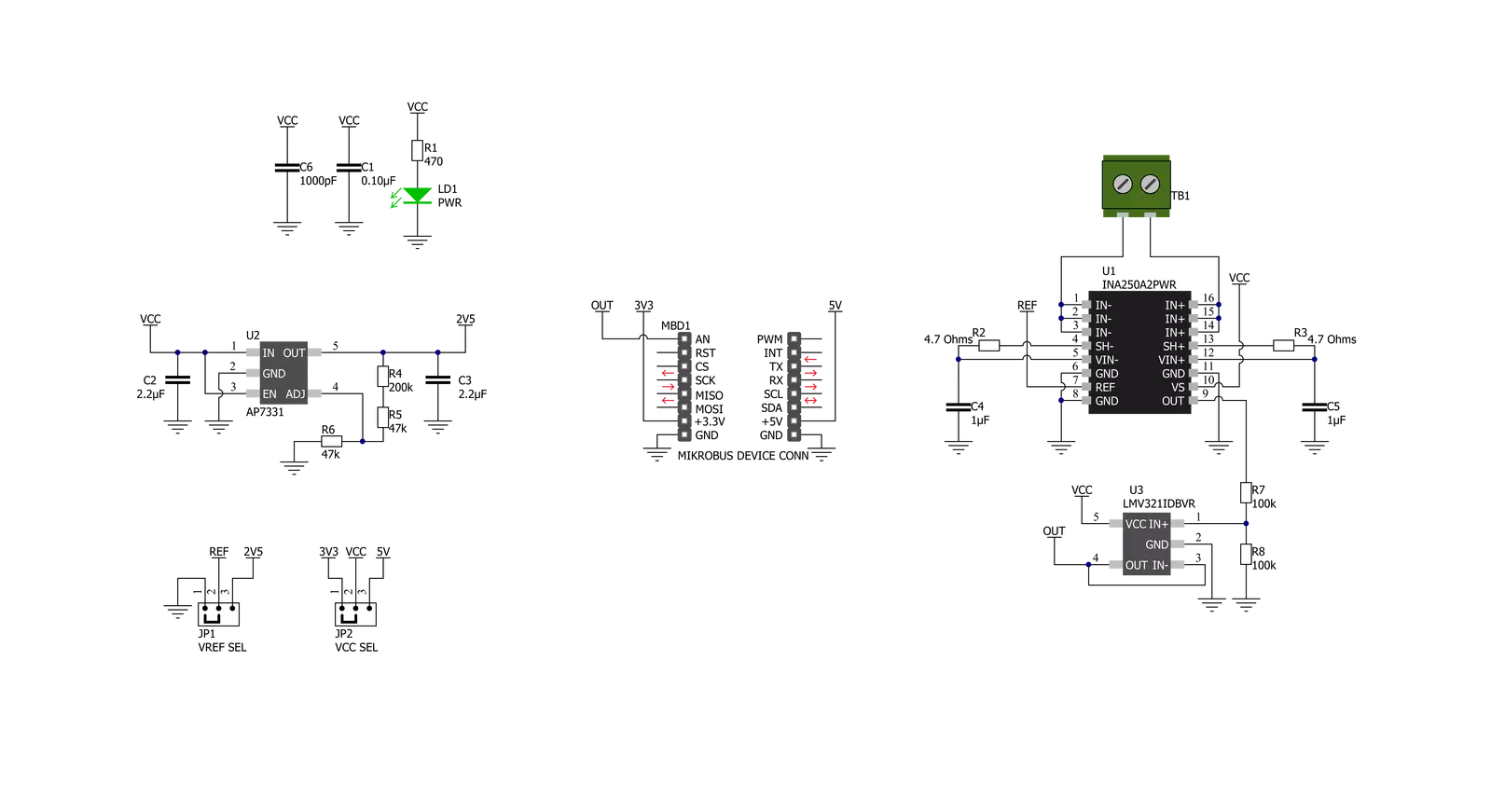
Current 4 Click基于德州仪器的INA250,这是一款带有高精度、低漂移电阻的电流传感放大器,可在很宽的温度范围内提供高精度的测量。INA250在电流通过时测量内部电流感测电阻上产生的电压。集成的2mΩ电流分流电阻具有0.1%的容差和15ppm/°C的低漂移,使最终设备性能更高。该放大器允许在共模电压下进行高精度电流测量,并在很宽的温度范围内提供最大0.84%的误差。Current 4 Click只使用一个引脚与MCU通信,该引脚路由到mikroBUS™插座的AN引脚上。来自
INA250的输出模拟信号被转发到运算放大器的输入,该运算放大器是德州仪器的LMV321低压轨对轨OpAmp,是需要低电压操作的应用中最经济的解决方案。LMV321 OpAmp的输出具有稳定的单位增益,充当缓冲器,以便主机MCU可以通过mikroBUS™插座的AN引脚对INA250的输出电压进行采样。INA250可以配置为通过参考电压级别测量单向和双向电流。对于单向操作,参考引脚应与地连接。当电流增加时,输出信号从此参考电压(或在这种情况下地)向上增加。对于双向电流,
可以使用外部电压源作为参考电压;在这种情况下,Diodes Incorporated的低压降线性稳压器AP7331为INA250提供2.5V的参考供电电压。通过将标记为VREF SEL的SMD跳线器定位到适当的位置,可以选择参考电压级别,选择由AP7331提供的2.5V或GND之间。此Click板可以通过VCC SEL跳线选择3.3V或5V逻辑电压级别运行。这样,既支持3.3V又支持5V的MCU可以正确使用通信线路。此外,此Click板配备了一个包含易于使用的函数和示例代码的库,可用作进一步开发的参考。


功能概述
开发板
32L496GDISCOVERY Discovery 套件是一款功能全面的演示和开发平台,专为搭载 Arm® Cortex®-M4 内核的 STM32L496AG 微控制器设计。该套件适用于需要在高性能、先进图形处理和超低功耗之间取得平衡的应用,支持无缝原型开发,适用于各种嵌入式解决方案。STM32L496AG 采用创新的节能架构,集成
了扩展 RAM 和 Chrom-ART 图形加速器,在提升图形性能的同时保持低功耗,使其特别适用于音频处理、图形用户界面和实时数据采集等对能效要求较高的应用。为了简化开发流程,该开发板配备了板载 ST-LINK/V2-1 调试器/编程器,提供即插即用的调试和编程体验,使用户无需额外硬件即可轻松加载、调
试和测试应用程序。凭借低功耗特性、增强的内存能力以及内置调试工具,32L496GDISCOVERY 套件是开发先进嵌入式系统、实现高效能解决方案的理想选择。

微控制器概述
MCU卡片 / MCU

建筑
ARM Cortex-M4
MCU 内存 (KB)
1024
硅供应商
STMicroelectronics
引脚数
169
RAM (字节)
327680
使用的MCU引脚
mikroBUS™映射器
“仔细看看!”
Click board™ 原理图
一步一步来
项目组装

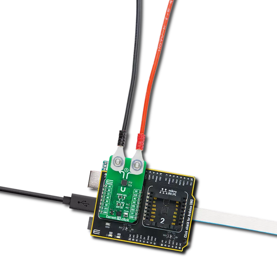
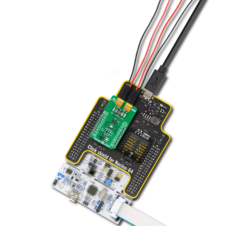
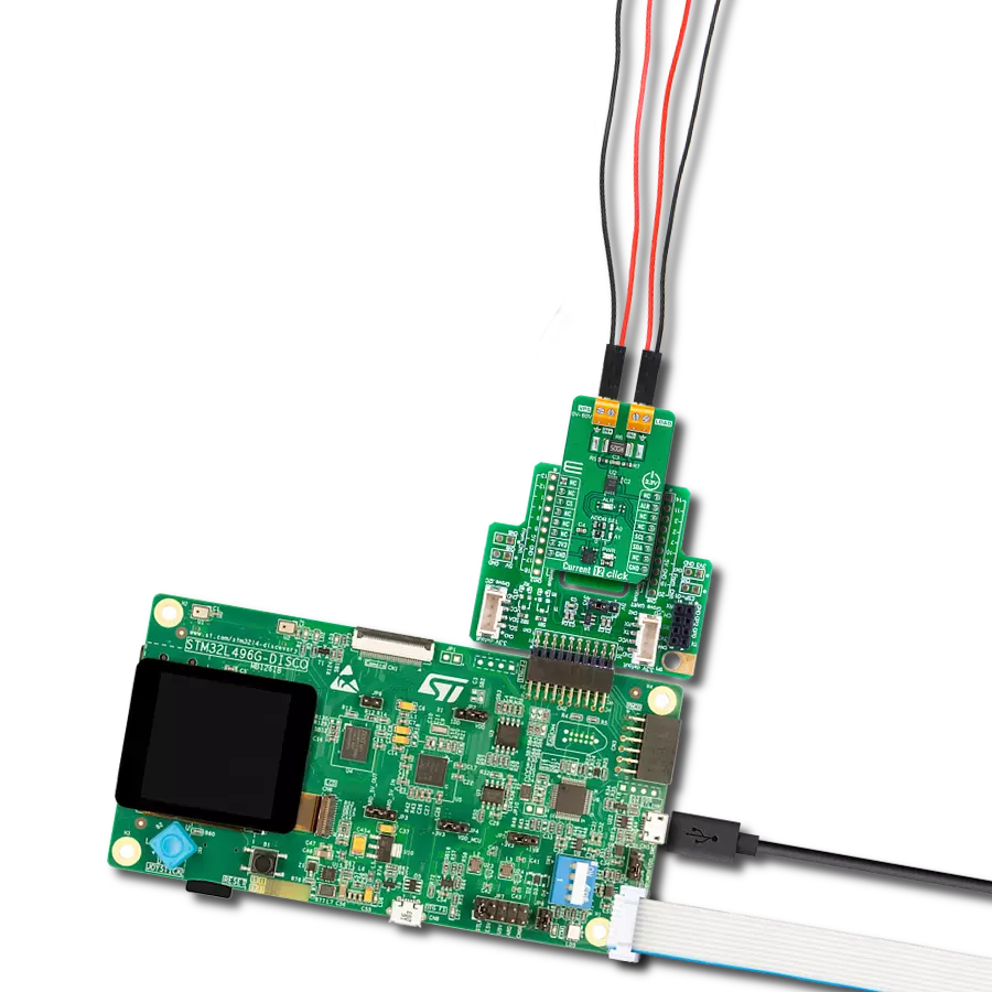
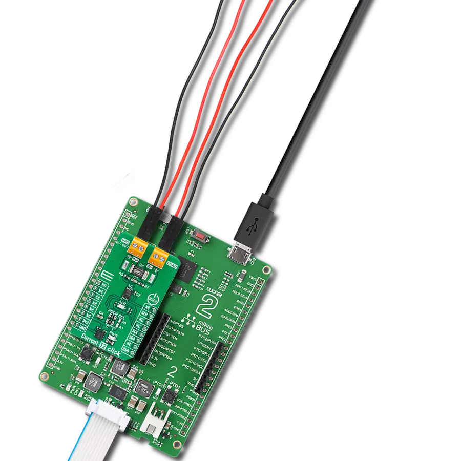
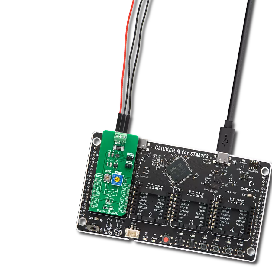
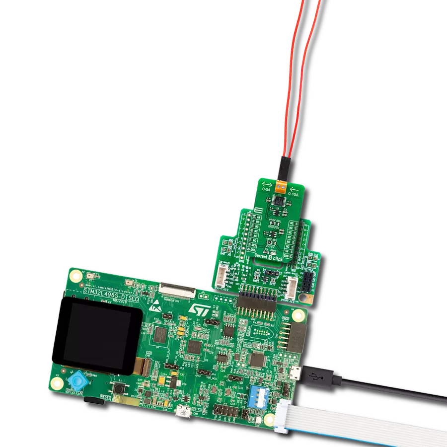
从选择您的开发板和Click板™开始。以Discovery kit with STM32L496AG MCU作为您的开发板开始。


软件支持
库描述
该库包含 Current 4 Click 驱动程序的 API。
关键功能:
current4_read_load_current- 读取负载电流current4_read_an_pin_voltage- 读取AN引脚电压水平功能current4_read_an_pin_value- 读取AN引脚数值功能
开源
代码示例
完整的应用程序代码和一个现成的项目可以通过NECTO Studio包管理器直接安装到NECTO Studio。 应用程序代码也可以在MIKROE的GitHub账户中找到。
/*!
* @file main.c
* @brief Current 4 Click Example.
*
* # Description
* This example showcases the ability of the Current 4 Click board.
* It configures Host MCU for communication and reads the voltage
* of AN pin and calculates current on load output.
*
* The demo application is composed of two sections :
*
* ## Application Init
* Initialization of the communication modules(ADC and UART).
*
* ## Application Task
* In span on 500ms reads voltage and calculates the current on load.
*
* @author Luka Filipovic
*
*/
#include "board.h"
#include "log.h"
#include "current4.h"
static current4_t current4; /**< Current 4 Click driver object. */
static log_t logger; /**< Logger object. */
void application_init ( void )
{
log_cfg_t log_cfg; /**< Logger config object. */
current4_cfg_t current4_cfg; /**< Click config object. */
/**
* Logger initialization.
* Default baud rate: 115200
* Default log level: LOG_LEVEL_DEBUG
* @note If USB_UART_RX and USB_UART_TX
* are defined as HAL_PIN_NC, you will
* need to define them manually for log to work.
* See @b LOG_MAP_USB_UART macro definition for detailed explanation.
*/
LOG_MAP_USB_UART( log_cfg );
log_init( &logger, &log_cfg );
log_info( &logger, " Application Init " );
// Click initialization.
current4_cfg_setup( ¤t4_cfg );
CURRENT4_MAP_MIKROBUS( current4_cfg, MIKROBUS_1 );
if ( ADC_ERROR == current4_init( ¤t4, ¤t4_cfg ) )
{
log_error( &logger, " Application Init Error. " );
log_info( &logger, " Please, run program again... " );
for ( ; ; );
}
log_info( &logger, " Application Task " );
}
void application_task ( void )
{
float current4_load_current = 0;
if ( ADC_ERROR != current4_read_load_current ( ¤t4, ¤t4_load_current ) )
{
log_printf( &logger, " > Load current : %.2f[A]\r\n", current4_load_current );
log_printf( &logger, "**********************\r\n" );
}
Delay_ms ( 500 );
}
int main ( void )
{
/* Do not remove this line or clock might not be set correctly. */
#ifdef PREINIT_SUPPORTED
preinit();
#endif
application_init( );
for ( ; ; )
{
application_task( );
}
return 0;
}
// ------------------------------------------------------------------------ END
额外支持
资源
类别:电流传感器