使用ACS70331和STM32F302VC创建一个可靠的工具来监控、分析和管理电流
通往精确电流测量的路径
已发布 7月 22, 2025
点击板
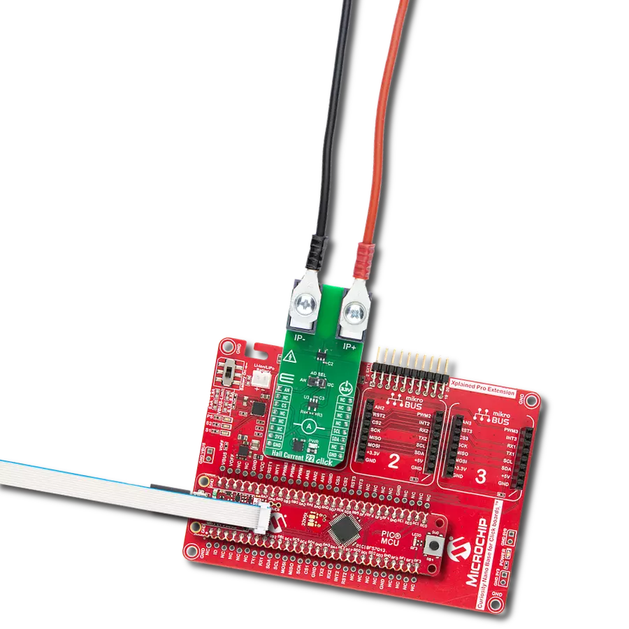
Hall Current 4 Click
开发板
CLICKER 4 for STM32F302VCT6
编译器
NECTO Studio
微控制器单元
STM32F302VC
通过我们的数据驱动解决方案实现高效电流使用,带来成本节约、生产力提升和卓越运营。
A
A
硬件概览
它是如何工作的?
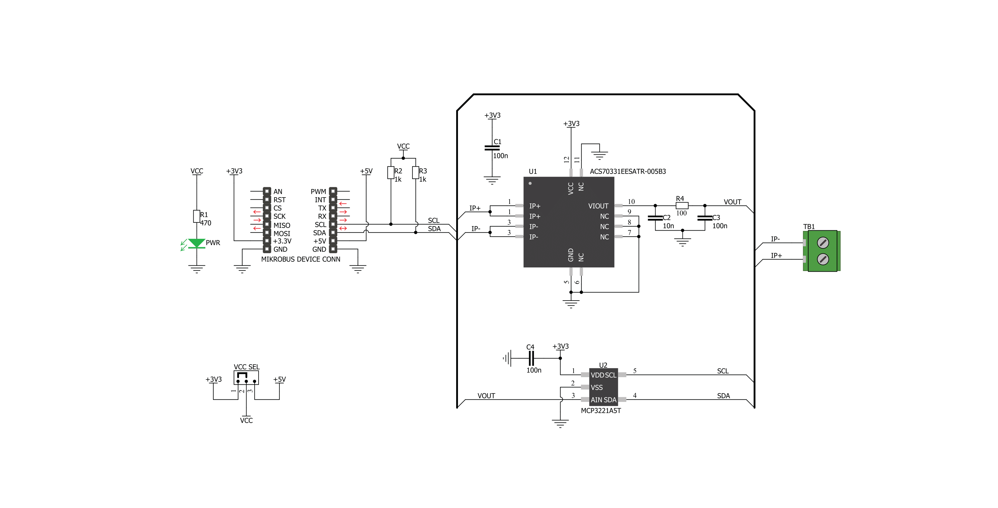
Hall Current 4 Click基于Allegro Microsystems的ACS70331电流传感器和Microchip生产的12位ADC MCP3221。ACS70331使用巨磁阻(GMR)元件通过感应电流产生的磁场间接测量流经IC主导体的电流。流经主导体的电流产生的磁场影响GMR传感器的电压,即使在低磁场强度下,GMR传感器电压也会变化,这使得ACS70331非常
适合精确测量较低电流。然而,它在较高电流下很快就会饱和,因此不适合较高电流测量。ACS70331的灵敏度为200 mV/A,可测量范围为-5A至+5A。考虑到ACS70331的工作范围约为1 MHz,负载电流变化引起的输出电压变化非常迅速且无延迟。ACS70331的输出电压被送到模数转换器(ADC)的输入端,允许通过I2C接口读取转换数据。ACS70331的主
导体电阻仅为1.1 mΩ,导致低功耗和由于电流流过传感器引起的低温升。传感器与芯片上的输出引脚没有物理接触,因为它完全通过流经输入引脚(主导体)的电流产生的磁场工作。输入引脚的负载电压与芯片的其余部分隔离。然而,在高于100V的电压下使用是不安全的。


功能概述
开发板
Clicker 4 for STM32F3 是一款紧凑型开发板,作为完整的解决方案而设计,可帮助用户快速构建具备独特功能的定制设备。该板搭载 STMicroelectronics 的 STM32F302VCT6 微控制器,配备四个 mikroBUS™ 插槽用于连接 Click boards™、完善的电源管理功能以及其他实用资源,是快速开发各类应用的理想平台。其核心 MCU STM32F302VCT6 基于高性能
Arm® Cortex®-M4 32 位处理器,运行频率高达 168MHz,处理能力强大,能够满足各种高复杂度任务的需求,使 Clicker 4 能灵活适应多种应用场景。除了两个 1x20 引脚排针外,板载最显著的连接特性是四个增强型 mikroBUS™ 插槽,支持接入数量庞大的 Click boards™ 生态系统,该生态每日持续扩展。Clicker 4 各功能区域标识清晰,界面直观简洁,极大
提升使用便捷性和开发效率。Clicker 4 的价值不仅在于加速原型开发与应用构建阶段,更在于其作为独立完整方案可直接集成至实际项目中,无需额外硬件修改。四角各设有直径 4.2mm(0.165")的安装孔,便于通过螺丝轻松固定。对于多数应用,只需配套一个外壳,即可将 Clicker 4 开发板转化为完整、实用且外观精美的定制系统。

微控制器概述
MCU卡片 / MCU

建筑
ARM Cortex-M4
MCU 内存 (KB)
256
硅供应商
STMicroelectronics
引脚数
100
RAM (字节)
40960
使用的MCU引脚
mikroBUS™映射器
“仔细看看!”
Click board™ 原理图
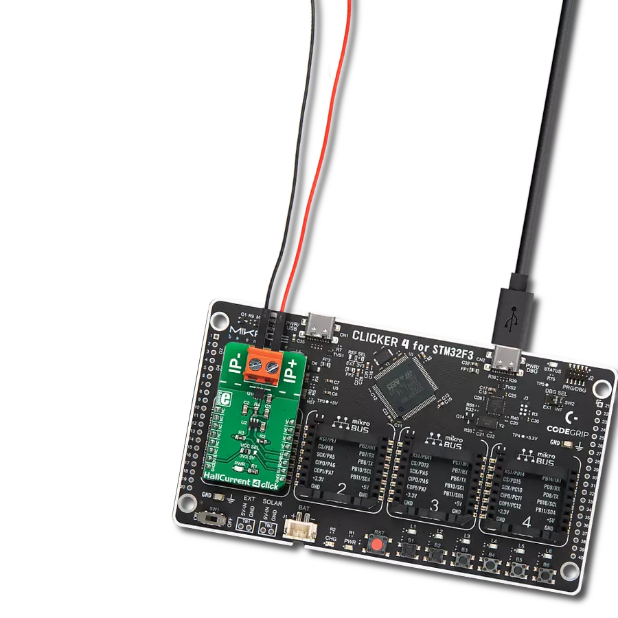
一步一步来
项目组装

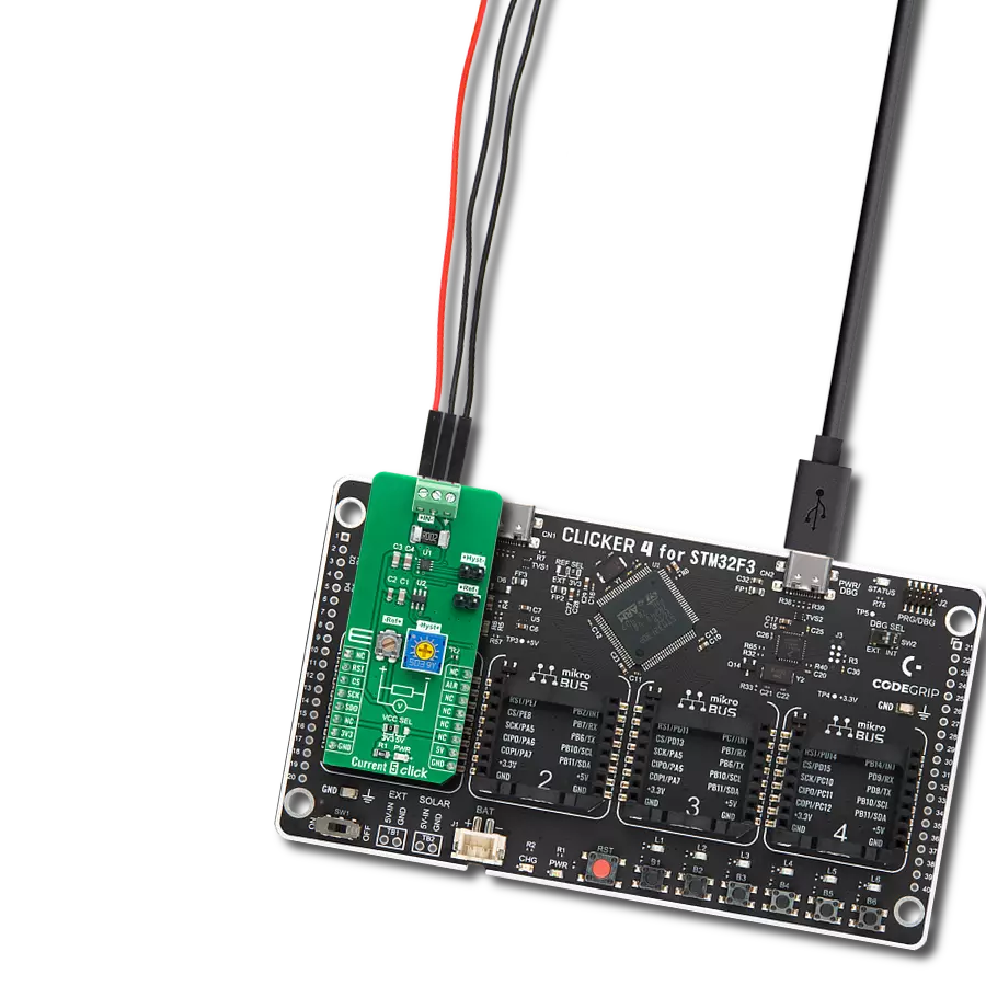
从选择您的开发板和Click板™开始。以CLICKER 4 for STM32F302VCT6作为您的开发板开始。


软件支持
库描述
该库包含用于Hall Current 4 Click驱动程序的API。
关键功能:
hallcurrent4_get_current_data- 该功能读取电流(单位:mA)hallcurrent4_get_raw_data- 该功能读取原始(ADC)电流数据
开源
代码示例
完整的应用程序代码和一个现成的项目可以通过NECTO Studio包管理器直接安装到NECTO Studio。 应用程序代码也可以在MIKROE的GitHub账户中找到。
/*!
 * \file
 * \brief HallCurrent4 Click example
 *
 * # Description
 * Demo application shows is reading current data in mA using Hall current 4 Click.
 *
 * The demo application is composed of two sections :
 *
 * ## Application Init
 * Configuring Clicks and log objects.
 *
 * ## Application Task
 * Reads Current value in mA and logs this data to USBUART every 1 sec.
 *
 * \author Katarina Perendic
 *
 */
// ------------------------------------------------------------------- INCLUDES

#include "board.h"
#include "log.h"
#include "hallcurrent4.h"

// ------------------------------------------------------------------ VARIABLES

static hallcurrent4_t hallcurrent4;
static log_t logger;

// ------------------------------------------------------ APPLICATION FUNCTIONS

void application_init ( void )
{
    log_cfg_t log_cfg;
    hallcurrent4_cfg_t cfg;

    /**
     * Logger initialization.
     * Default baud rate: 115200
     * Default log level: LOG_LEVEL_DEBUG
     * @note If USB_UART_RX and USB_UART_TX
     * are defined as HAL_PIN_NC, you will
     * need to define them manually for log to work.
     * See @b LOG_MAP_USB_UART macro definition for detailed explanation.
     */
    LOG_MAP_USB_UART( log_cfg );
    log_init( &logger, &log_cfg );
    log_info( &logger, "---- Application Init ----" );

    //  Click initialization.

    hallcurrent4_cfg_setup( &cfg );
    HALLCURRENT4_MAP_MIKROBUS( cfg, MIKROBUS_1 );
    hallcurrent4_init( &hallcurrent4, &cfg );
}

void application_task ( void )
{
    float current;

    current = hallcurrent4_get_current_data( &hallcurrent4 );

    log_printf( &logger, " >> Current value: %.2f mA\r\n", current );
    log_printf( &logger, " ------------------------- \r\n" );
    Delay_ms ( 1000 );
}

int main ( void )
{
    /* Do not remove this line or clock might not be set correctly. */
    #ifdef PREINIT_SUPPORTED
    preinit();
    #endif

    application_init( );

    for ( ; ; )
    {
        application_task( );
    }

    return 0;
}


// ------------------------------------------------------------------------ END
额外支持
资源
类别:电流传感器