使用MAX6675和STM32F302VC在任何环境中获得可靠数据以做出明智决策
确定度:使用我们的热电偶——准确性的高手,改善您的测量
已发布 7月 22, 2025
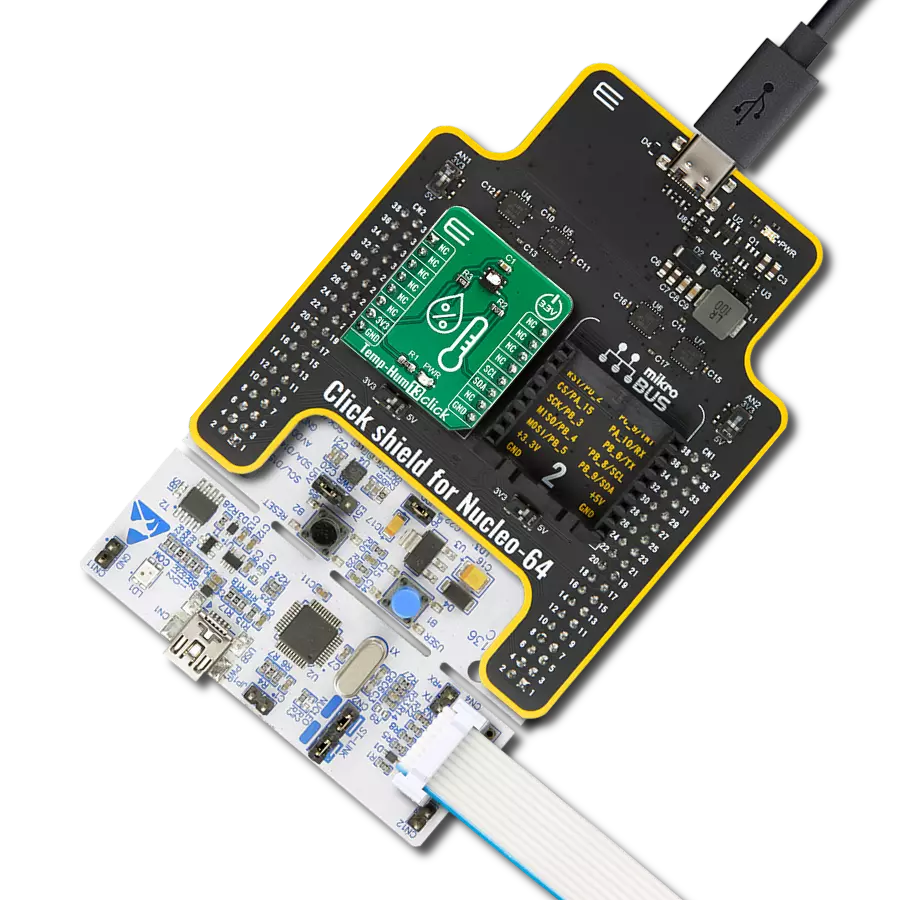
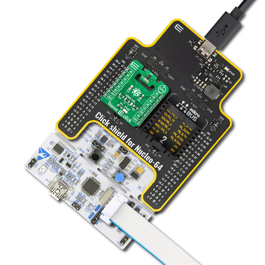
点击板
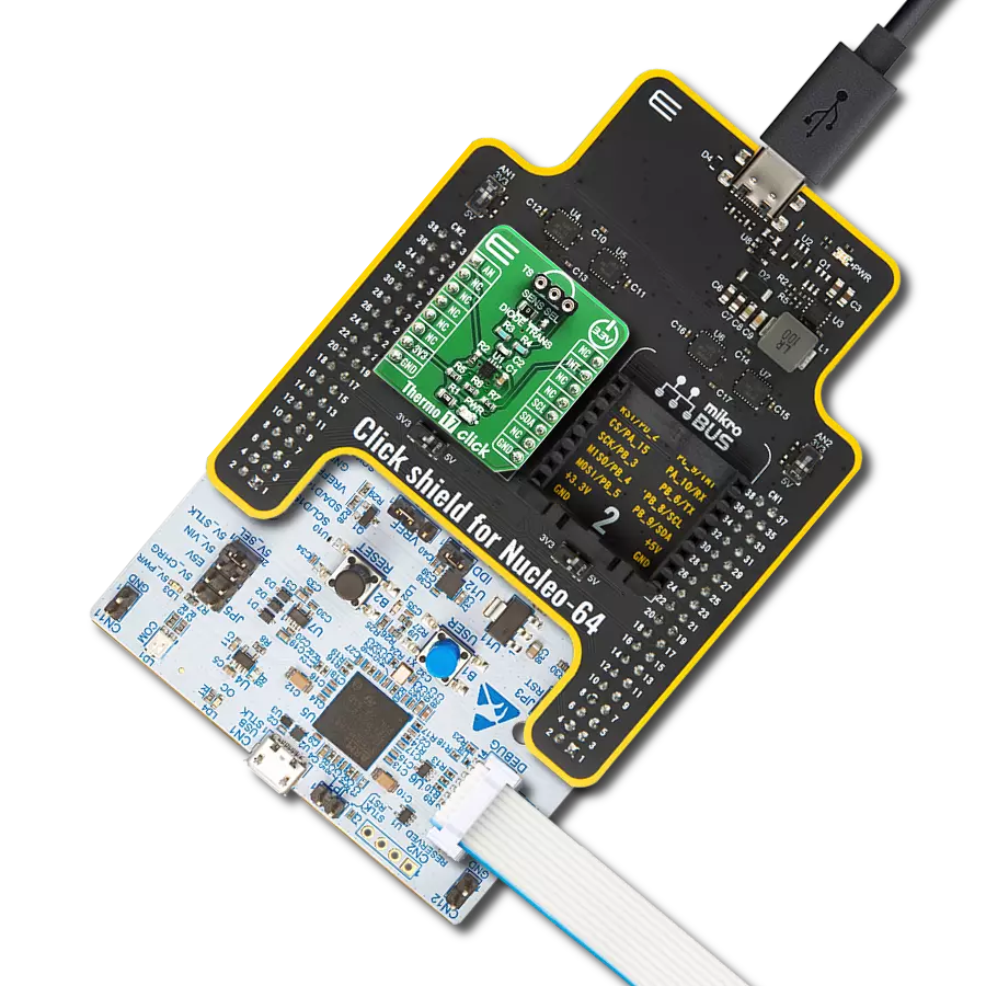
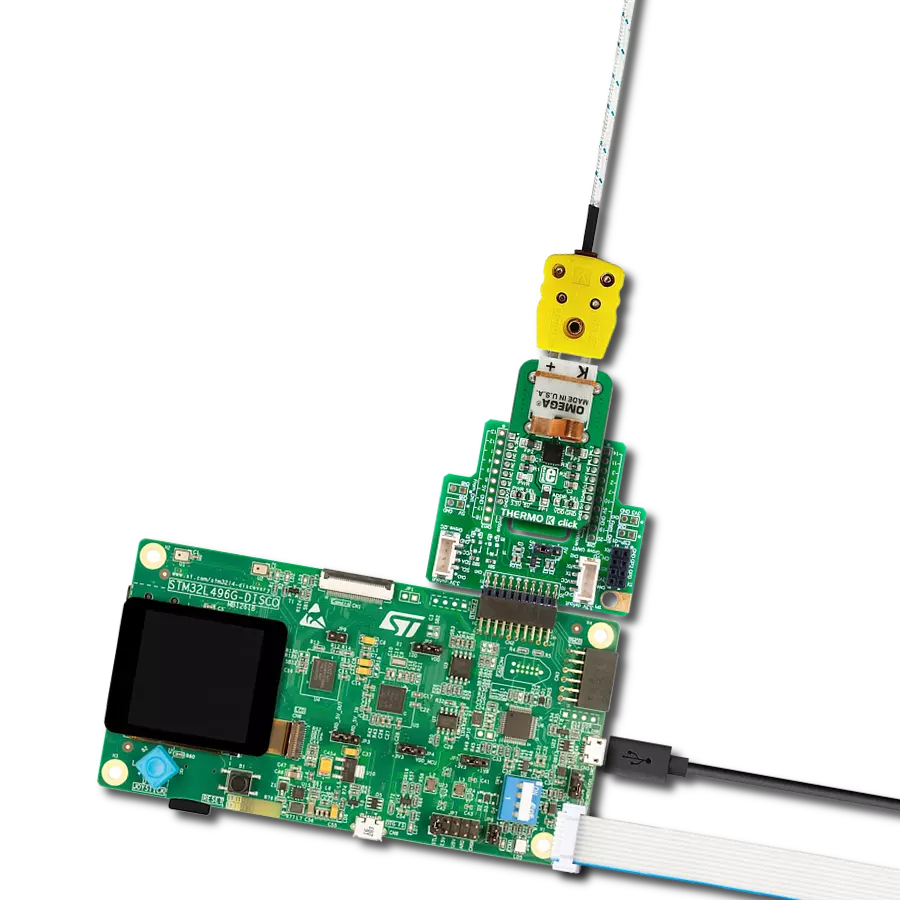
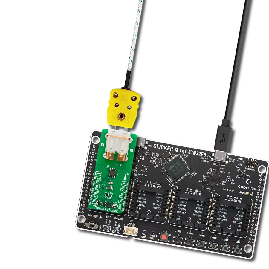
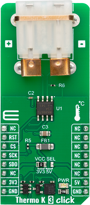
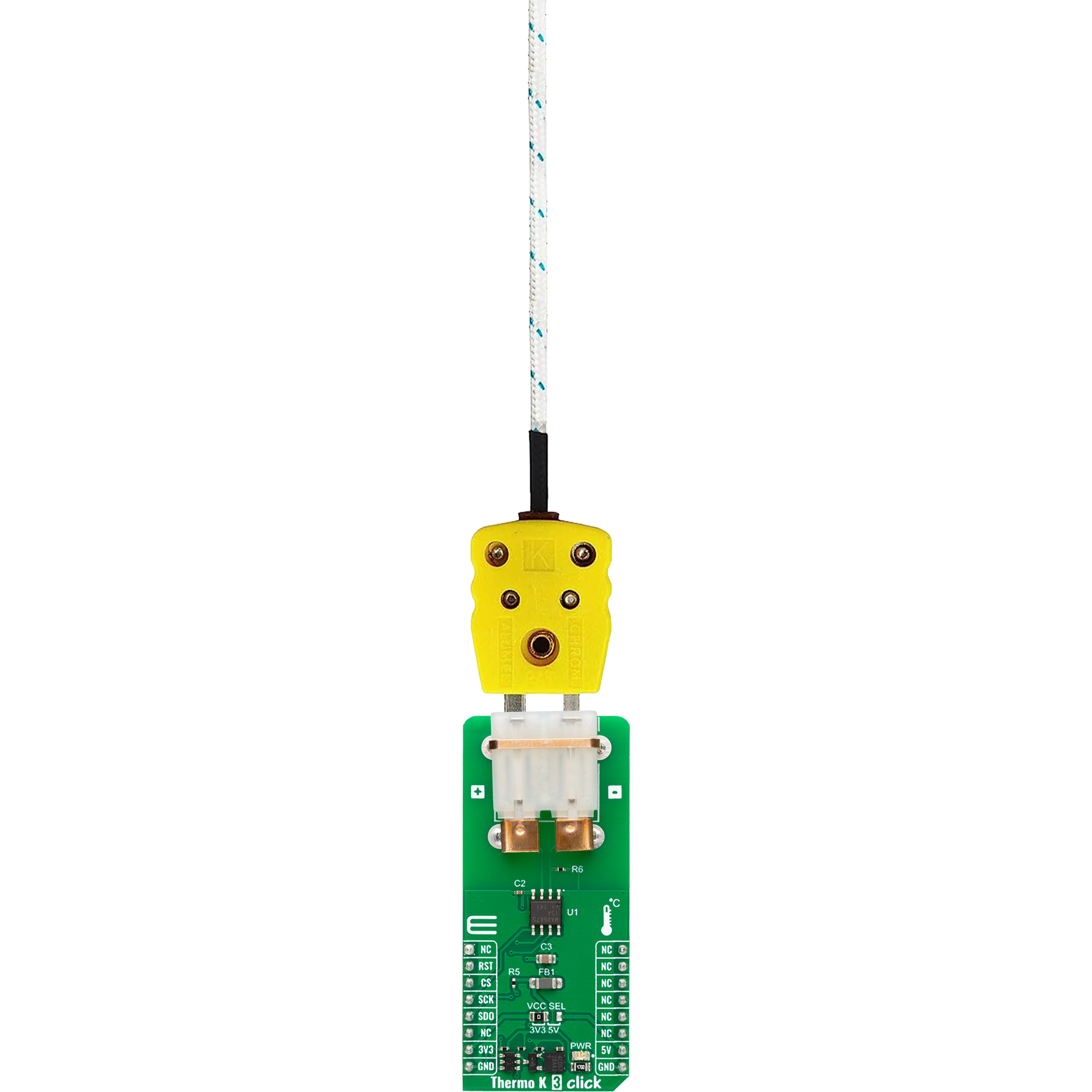
Thermo K 3 Click
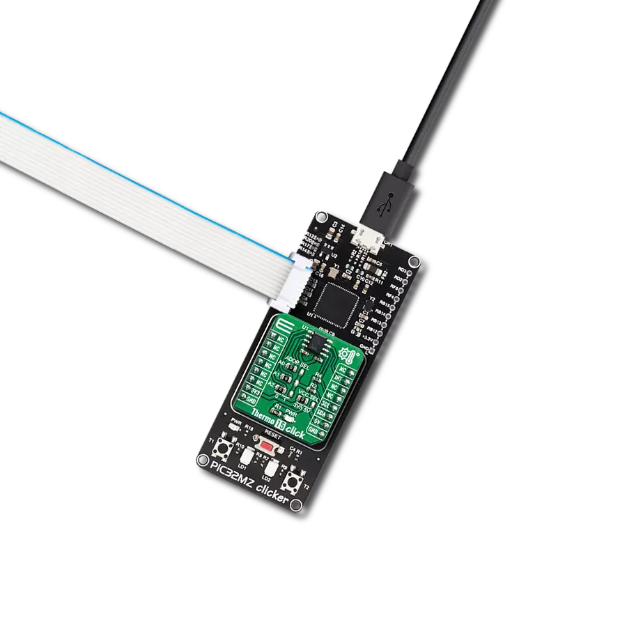
开发板
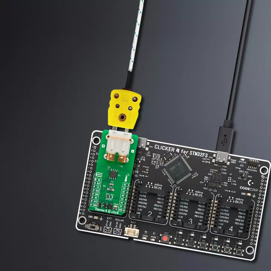
CLICKER 4 for STM32F302VCT6
编译器
NECTO Studio
微控制器单元
STM32F302VC
当涉及到温度测量时,细节至关重要。我们的热电偶探头解决方案超越了标准测量,提供卓越的精度,使您的数据更加清晰,每一度都至关重要。
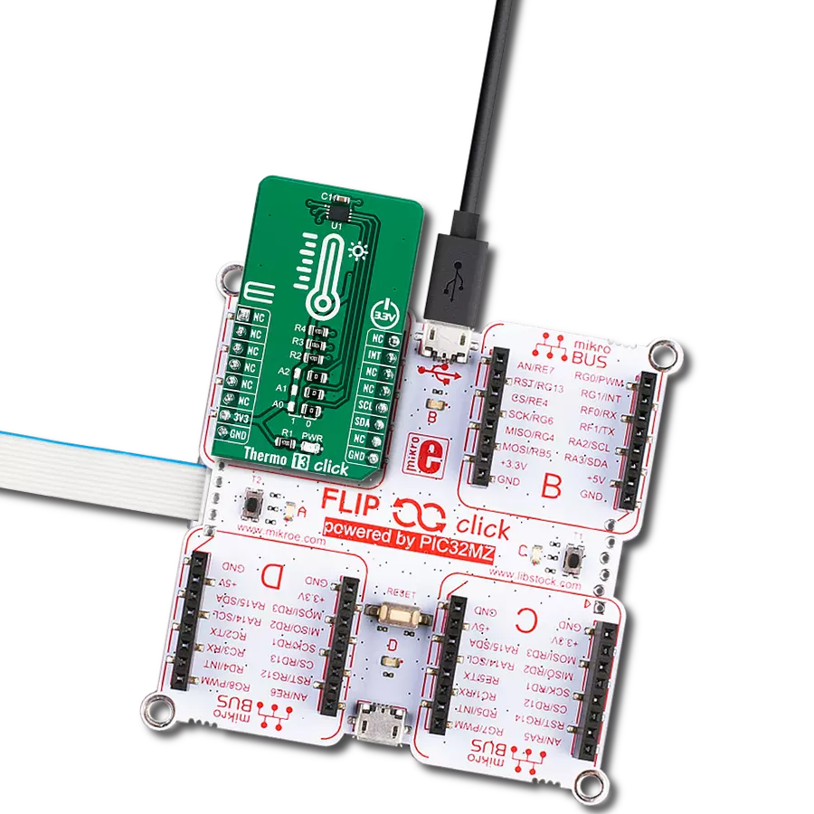
A
A
硬件概览
它是如何工作的?
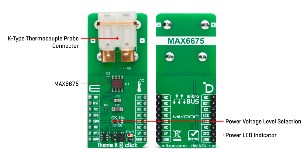
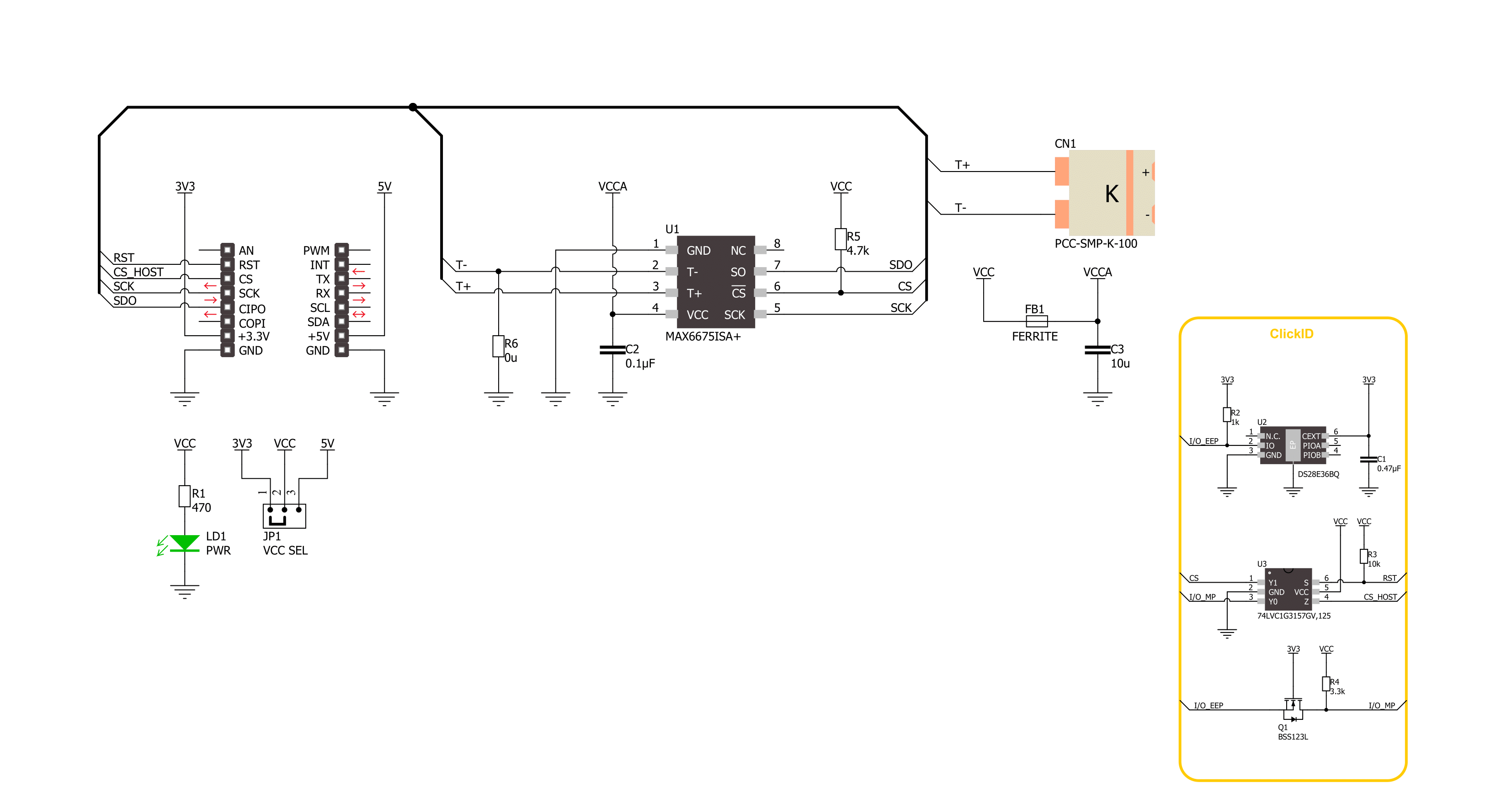
Thermo K 3 Click 基于 Analog Devices 的 MAX6675,这是一款带有冷端补偿的 K 型热电偶到数字转换器。它包括信号调理硬件,将热电偶信号转换为与 ADC 输入通道兼容的电压。热电偶电路由热端和冷端组成:热端是热电偶探头本身(0°C - 102.75°C),冷端是环境温度,通常是电路板本身(-20°C - 85°C)。MAX6675 通过补偿
冷端来感应热电偶两端的温差并进行校正。MAX6675 测量热电偶输出和感应二极管的电压,并将其传递给存储在 ADC 中的内部转换功能。Thermo K 3 Click 使用 3 线(只读)SPI 串行接口与主 MCU 通信,时钟频率最高可达 4.3MHz。除了温度,您还可以获取开路热电偶检测的数据。为了实现这一功能,PCC-SMP 连接器的 T- 通过 R6
0Ω 电阻接地。如果不需要此功能或不适合您的需求,可以将其焊接掉。此 Click board™ 可以通过 VCC SEL 跳线选择 3.3V 或 5V 逻辑电压电平进行操作。这样,3.3V 和 5V 的 MCU 都可以正确使用通信线路。此外,此 Click board™ 配备了包含易于使用的函数和示例代码的库,可用于进一步开发。
功能概述
开发板
Clicker 4 for STM32F3 是一款紧凑型开发板,作为完整的解决方案而设计,可帮助用户快速构建具备独特功能的定制设备。该板搭载 STMicroelectronics 的 STM32F302VCT6 微控制器,配备四个 mikroBUS™ 插槽用于连接 Click boards™、完善的电源管理功能以及其他实用资源,是快速开发各类应用的理想平台。其核心 MCU STM32F302VCT6 基于高性能
Arm® Cortex®-M4 32 位处理器,运行频率高达 168MHz,处理能力强大,能够满足各种高复杂度任务的需求,使 Clicker 4 能灵活适应多种应用场景。除了两个 1x20 引脚排针外,板载最显著的连接特性是四个增强型 mikroBUS™ 插槽,支持接入数量庞大的 Click boards™ 生态系统,该生态每日持续扩展。Clicker 4 各功能区域标识清晰,界面直观简洁,极大
提升使用便捷性和开发效率。Clicker 4 的价值不仅在于加速原型开发与应用构建阶段,更在于其作为独立完整方案可直接集成至实际项目中,无需额外硬件修改。四角各设有直径 4.2mm(0.165")的安装孔,便于通过螺丝轻松固定。对于多数应用,只需配套一个外壳,即可将 Clicker 4 开发板转化为完整、实用且外观精美的定制系统。

微控制器概述
MCU卡片 / MCU

建筑
ARM Cortex-M4
MCU 内存 (KB)
256
硅供应商
STMicroelectronics
引脚数
100
RAM (字节)
40960
你完善了我!
配件
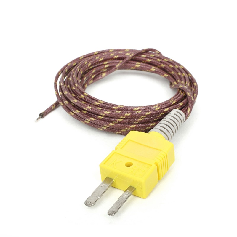
这款配备玻璃编织绝缘的K型热电偶探头是专为精密温度测量设计的多功能工具,特别适用于高温环境。采用校准的K型配置和2米长的24 AWG规格线,这款探头能够提供可靠的读数。其工作温度范围可达480°C(900°F),适合苛刻的应用环境。玻璃编织绝缘保证了测量过程中的耐用性和稳定性,连接器主体可承受高达220°C(425°F)的温度。K型热电偶探头末端配有PCC-SMP连接器,与THERMO Click和Thermo K Click板兼容。这种连接性使其成为各种工业和科学环境中温度监测的宝贵工具,在这些环境中,精度和可靠性至关重要。
使用的MCU引脚
mikroBUS™映射器
“仔细看看!”
Click board™ 原理图
一步一步来
项目组装

从选择您的开发板和Click板™开始。以CLICKER 4 for STM32F302VCT6作为您的开发板开始。


软件支持
库描述
该库包含 Thermo K 3 Click 驱动程序的 API。
关键功能:
thermok3_read_data- Examplethermok3_convert_to_celsius- Example
开源
代码示例
完整的应用程序代码和一个现成的项目可以通过NECTO Studio包管理器直接安装到NECTO Studio。 应用程序代码也可以在MIKROE的GitHub账户中找到。
/*!
 * @file main.c
 * @brief Thermo K 3 Click example
 *
 * # Description
 * This example demonstrates the use of Thermo K 3 Click board by reading and displaying
 * the temperature measurements.
 *
 * The demo application is composed of two sections :
 *
 * ## Application Init
 * Initializes the driver and logger.
 *
 * ## Application Task
 * Reads the temperature measurement in Celsius and displays the results on the USB UART
 * approximately once per second. If there's no thermocouple type-K probe inserted an
 * appropriate message will be displayed instead.
 *
 * @author Stefan Filipovic
 *
 */

#include "board.h"
#include "log.h"
#include "thermok3.h"

static thermok3_t thermok3;
static log_t logger;

void application_init ( void )
{
    log_cfg_t log_cfg;  /**< Logger config object. */
    thermok3_cfg_t thermok3_cfg;  /**< Click config object. */

    /**
     * Logger initialization.
     * Default baud rate: 115200
     * Default log level: LOG_LEVEL_DEBUG
     * @note If USB_UART_RX and USB_UART_TX
     * are defined as HAL_PIN_NC, you will
     * need to define them manually for log to work.
     * See @b LOG_MAP_USB_UART macro definition for detailed explanation.
     */
    LOG_MAP_USB_UART( log_cfg );
    log_init( &logger, &log_cfg );
    log_info( &logger, " Application Init " );

    // Click initialization.
    thermok3_cfg_setup( &thermok3_cfg );
    THERMOK3_MAP_MIKROBUS( thermok3_cfg, MIKROBUS_1 );
    if ( SPI_MASTER_ERROR == thermok3_init( &thermok3, &thermok3_cfg ) )
    {
        log_error( &logger, " Communication init." );
        for ( ; ; );
    }

    log_info( &logger, " Application Task " );
}

void application_task ( void )
{
    float temperature = 0;
    err_t error_flag = thermok3_read_temperature ( &thermok3, &temperature );
    if ( THERMOK3_OK == error_flag )
    {
        log_printf( &logger, " Temperature: %.2f C\r\n\n", temperature );
    }
    else if ( THERMOK3_OPEN_THERMOCOUPLE == error_flag )
    {
        log_printf( &logger, " NO thermocouple input\r\n\n" );
    }
    Delay_ms ( 1000 );
}

int main ( void )
{
    /* Do not remove this line or clock might not be set correctly. */
    #ifdef PREINIT_SUPPORTED
    preinit();
    #endif

    application_init( );

    for ( ; ; )
    {
        application_task( );
    }

    return 0;
}

// ------------------------------------------------------------------------ END
额外支持
资源
类别:温度与湿度