使用CT455-H06B5-TS08和PIC32MZ2048EFH100实现高灵敏度和低误差的精确电流测量
XtremeSense™ TMR无芯电流感应解决方案
已发布 10月 04, 2024
点击板
Current 10 Click
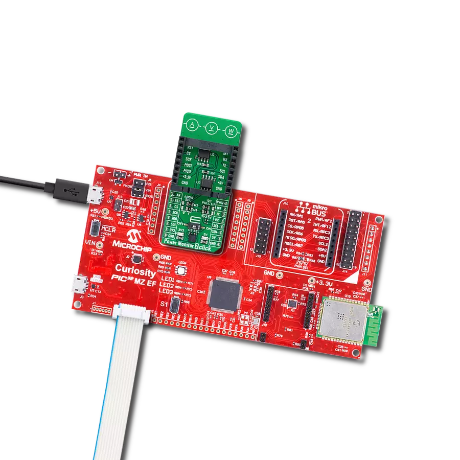
开发板
Flip&Click PIC32MZ
编译器
NECTO Studio
微控制器单元
PIC32MZ2048EFH100
通过最小误差测量电流使用量,实现精确计费和能源管理
A
A
硬件概览
它是如何工作的?
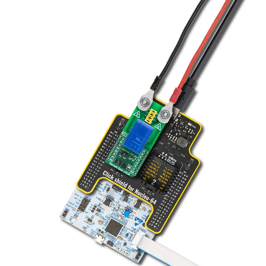
Current 10 Click基于Allegro Microsystems的CT455 (CT455-H06B5-TS08),这是一款XtremeSense™ TMR(隧道磁阻)无芯电流传感器,具有1MHz的宽带宽。该传感器采用Allegro的专利XtremeSense™技术,确保高精度电流测量并具有极低的噪声。凭借其高精度和强大的功能,Current 10 Click是需要可靠电流感应的应用的理想解决方案,广泛适用于消费级、工业级和企业级应用,如太阳能逆变器、电池管理系统、DC/DC转换器、工业设备和电力计量仪表。
CT455传感器在双极模式下运行,能够检测正负电流流动,且其灵敏度为333.3mV/mT,提供精确的测量能力。CT455由5V电源供电,可以检测±6mT范围内的磁场,并将其转换为线性模拟输出电压。这使得该板能够以低于±1.0%的误差,准确捕捉温度和电源电压变化下的电流变化,确保在各种操作条件下的可靠性能。CT455的输出信号可以通过Microchip的MCP3221 A/D转换器(具有12位分辨率的逐次逼近ADC)转换为数字值,使用2线I2C兼容接口,或者直
接发送到mikroBUS™插座上的模拟引脚(标记为AN)。输出选择可以通过板载SMD跳线(标记为OUT SEL)进行选择,跳线位置为AN和ADC。此Click板™可以通过VCC SEL跳线选择在3.3V或5V逻辑电压下运行,从而使支持3.3V和5V逻辑电平的MCU都能够正确使用通信线路。此外,该Click板™还配备了包含易于使用的函数和示例代码的库,可作为进一步开发的参考。

功能概述
开发板
Flip&Click PIC32MZ 是一款紧凑型开发板,设计为一套完整的解决方案,它将 Click 板™的灵活性带给您喜爱的微控制器,使其成为实现您想法的完美入门套件。它配备了一款板载 32 位 PIC32MZ 微控制器,Microchip 的 PIC32MZ2048EFH100,四个 mikroBUS™ 插槽用于 Click 板™连接,两个 USB 连接器,LED 指示灯,按钮,调试器/程序员连接器,以及两个与 Arduino-UNO 引脚兼容的头部。得益于创
新的制造技术,它允许您快速构建具有独特功能和特性的小工具。Flip&Click PIC32MZ 开发套件的每个部分都包含了使同一板块运行最高效的必要组件。此外,还可以选择 Flip&Click PIC32MZ 的编程方式,使用 chipKIT 引导程序(Arduino 风格的开发环境)或我们的 USB HID 引导程序,使用 mikroC、mikroBasic 和 mikroPascal for PIC32。该套件包括一个通过 USB 类型-C(USB-C)连接器的干净且调
节过的电源供应模块。所有 mikroBUS™ 本身支持的 通信方法都在这块板上,包括已经建立良好的 mikroBUS™ 插槽、用户可配置的按钮和 LED 指示灯。Flip&Click PIC32MZ 开发套件允许您在几分钟内创建新的应用程序。它由 Mikroe 软件工具原生支持,得益于大量不同的 Click 板™(超过一千块板),其数量每天都在增长,它涵盖了原型制作的许多方面。

微控制器概述
MCU卡片 / MCU

建筑
PIC32
MCU 内存 (KB)
2048
硅供应商
Microchip
引脚数
100
RAM (字节)
524288
使用的MCU引脚
mikroBUS™映射器
“仔细看看!”
Click board™ 原理图

一步一步来
项目组装

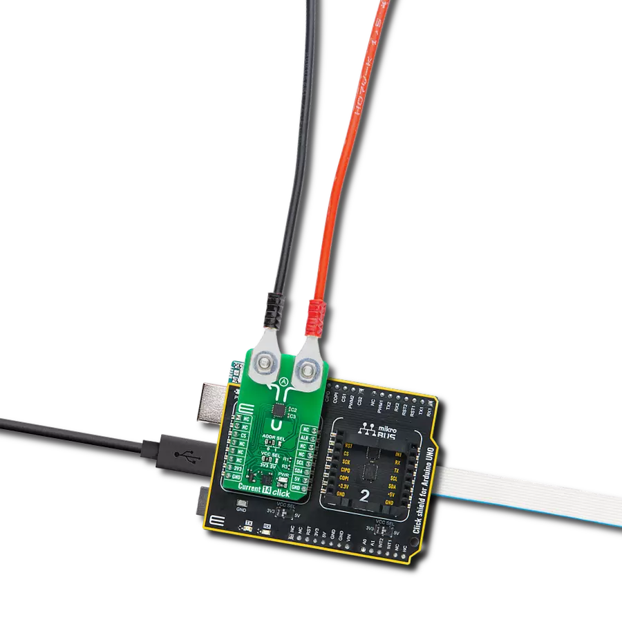
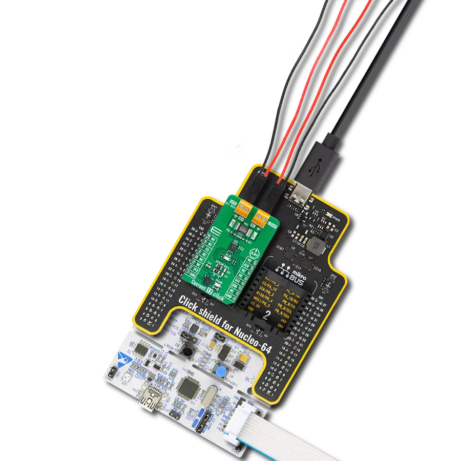
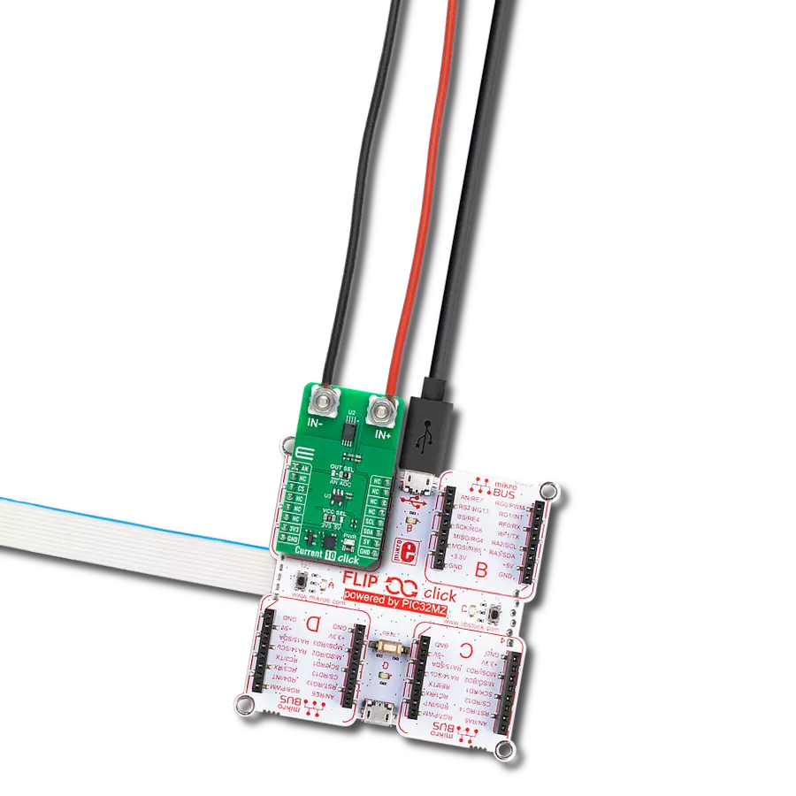
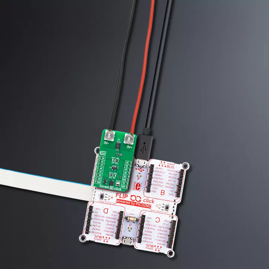
从选择您的开发板和Click板™开始。以Flip&Click PIC32MZ作为您的开发板开始。


软件支持
库描述
该库包含 NAME Click 驱动程序的 API。
关键功能:
current10_calib_offset- 此函数用于校准零电流的偏移值。current10_calib_resolution- 此函数用于在已知负载电流下校准数据分辨率。current10_read_current- 此函数用于读取输入电流值,单位为安培 [A]。
开源
代码示例
完整的应用程序代码和一个现成的项目可以通过NECTO Studio包管理器直接安装到NECTO Studio。 应用程序代码也可以在MIKROE的GitHub账户中找到。
/*!
* @file main.c
* @brief Current 10 Click Example.
*
* # Description
* This example demonstrates the use of Current 10 Click board by reading and
* displaying the input current measurements.
*
* The demo application is composed of two sections :
*
* ## Application Init
* Initializes the driver and calibrates the zero current offset and data resolution
* at 3A load current.
*
* ## Application Task
* Reads the input current measurements and displays the results on the USB UART
* approximately once per second.
*
* @note
* The measurement range is approximately: +/- 75A.
*
* @author Stefan Filipovic
*
*/
#include "board.h"
#include "log.h"
#include "current10.h"
// Load current [A] used for the data resolution calibration process.
#define CURRENT10_CALIBRATING_CURRENT 3.0f
static current10_t current10; /**< Current 10 Click driver object. */
static log_t logger; /**< Logger object. */
void application_init ( void )
{
log_cfg_t log_cfg; /**< Logger config object. */
current10_cfg_t current10_cfg; /**< Click config object. */
/**
* Logger initialization.
* Default baud rate: 115200
* Default log level: LOG_LEVEL_DEBUG
* @note If USB_UART_RX and USB_UART_TX
* are defined as HAL_PIN_NC, you will
* need to define them manually for log to work.
* See @b LOG_MAP_USB_UART macro definition for detailed explanation.
*/
LOG_MAP_USB_UART( log_cfg );
log_init( &logger, &log_cfg );
log_info( &logger, " Application Init " );
// Click initialization.
current10_cfg_setup( ¤t10_cfg );
CURRENT10_MAP_MIKROBUS( current10_cfg, MIKROBUS_1 );
err_t init_flag = current10_init( ¤t10, ¤t10_cfg );
if ( ( ADC_ERROR == init_flag ) || ( I2C_MASTER_ERROR == init_flag ) )
{
log_error( &logger, " Communication init." );
for ( ; ; );
}
log_printf( &logger, " Calibrating zero current offset in 5 seconds...\r\n" );
log_printf( &logger, " Make sure no current flows through the sensor during the calibration process.\r\n" );
for ( uint8_t cnt = 5; cnt > 0; cnt-- )
{
log_printf( &logger, " %u\r\n", ( uint16_t ) cnt );
Delay_ms ( 1000 );
}
if ( CURRENT10_ERROR == current10_calib_offset ( ¤t10 ) )
{
log_error( &logger, " Calibrate offset." );
for ( ; ; );
}
log_printf( &logger, " Offset calibration DONE.\r\n\n" );
log_printf( &logger, " Calibrating data resolution in 5 seconds...\r\n" );
log_printf( &logger, " Keep the load current set at %.1fA during the calibration process.\r\n",
CURRENT10_CALIBRATING_CURRENT );
for ( uint8_t cnt = 5; cnt > 0; cnt-- )
{
log_printf( &logger, " %u\r\n", ( uint16_t ) cnt );
Delay_ms ( 1000 );
}
if ( CURRENT10_ERROR == current10_calib_resolution ( ¤t10, CURRENT10_CALIBRATING_CURRENT ) )
{
log_error( &logger, " Calibrate resolution." );
for ( ; ; );
}
log_printf( &logger, " Data resolution calibration DONE.\r\n" );
log_info( &logger, " Application Task " );
}
void application_task ( void )
{
float current = 0;
if ( CURRENT10_OK == current10_read_current ( ¤t10, ¤t ) )
{
log_printf( &logger, " Current : %.1f A\r\n\n", current );
Delay_ms ( 1000 );
}
}
int main ( void )
{
/* Do not remove this line or clock might not be set correctly. */
#ifdef PREINIT_SUPPORTED
preinit();
#endif
application_init( );
for ( ; ; )
{
application_task( );
}
return 0;
}
// ------------------------------------------------------------------------ END
额外支持
资源
类别:电流传感器