Stay cool and dry with real-time climate insights using SHT21 and STM32L496AG
Don't sweat it – track temperature and humidity effortlessly

Published Jul 22, 2025
Click board™
Temp&Hum 8 Click
Dev. board
Discovery kit with STM32L496AG MCU
Compiler
NECTO Studio
MCU
STM32L496AG
Our goal is to help you create the perfect climate for success, maximizing productivity, and focus by offering intelligent climate monitoring solutions for your home or workplace
A
A
Hardware Overview
How does it work?
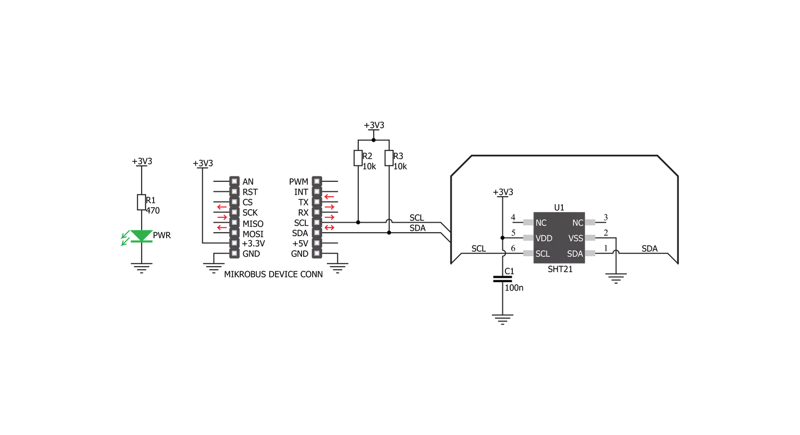
Temp&Hum 8 Click is based on the SHT21, a humidity and temperature digital sensor from Sensirion. This sensor is factory calibrated, allowing down to ±2% relative humidity tolerance (RH) and ±0.3°C thermal tolerance. However, the RH measurement of the sensor is affected by the temperature, therefore it is required to use the sensor at the temperature of the air, in which the humidity is measured. The humidity accuracy is also affected by the RH percentage: if both temperature and humidity are placed on a graph, it is possible to get a diagram of the RH accuracy as the function of RH percentage and temperature. The SHT21 IC is based on the CMOSens® technology, featuring the capacitive RH
sensor and the bandgap temperature sensor. Besides the sensing elements, the IC incorporates an analog front end (AFE), which consists of A/D converter, OTP memory, and a logic section. The integrated A/D converter can be programmatically selected from the lowest 8/12-bit resolution, up to resolutions of 12/14 bits. The resolution selection affects the power consumption, as well as the data output rate. The response time might vary between 3ms for 8-bit resolution, up to 29ms for 14-bit resolution, for the RH readings. The resolution selection can be set within the so-called User register. The SHT21 sensor also features an integrated heating element, used to evaporate condensation. The heating
element can be simply activated by setting a bit in the User register. In the case when the heater is powered on, the power consumption might rise above the typical values. The SHT21 sensor is also equipped with the brown-out status bit, located in the User register. This bit indicates the low power voltage: if the voltage drops below 2.25V, this bit will be set to 1, indicating a brown-out condition. This Click board™ can be operated only with a 3.3V logic voltage level. The board must perform appropriate logic voltage level conversion before using MCUs with different logic levels. Also, it comes equipped with a library containing functions and an example code that can be used as a reference for further development.

Features overview
Development board
The 32L496GDISCOVERY Discovery kit serves as a comprehensive demonstration and development platform for the STM32L496AG microcontroller, featuring an Arm® Cortex®-M4 core. Designed for applications that demand a balance of high performance, advanced graphics, and ultra-low power consumption, this kit enables seamless prototyping for a wide range of embedded solutions. With its innovative energy-efficient
architecture, the STM32L496AG integrates extended RAM and the Chrom-ART Accelerator, enhancing graphics performance while maintaining low power consumption. This makes the kit particularly well-suited for applications involving audio processing, graphical user interfaces, and real-time data acquisition, where energy efficiency is a key requirement. For ease of development, the board includes an onboard ST-LINK/V2-1
debugger/programmer, providing a seamless out-of-the-box experience for loading, debugging, and testing applications without requiring additional hardware. The combination of low power features, enhanced memory capabilities, and built-in debugging tools makes the 32L496GDISCOVERY kit an ideal choice for prototyping advanced embedded systems with state-of-the-art energy efficiency.

Microcontroller Overview
MCU Card / MCU

Architecture
ARM Cortex-M4
MCU Memory (KB)
1024
Silicon Vendor
STMicroelectronics
Pin count
169
RAM (Bytes)
327680
Used MCU Pins
mikroBUS™ mapper
Take a closer look
Click board™ Schematic
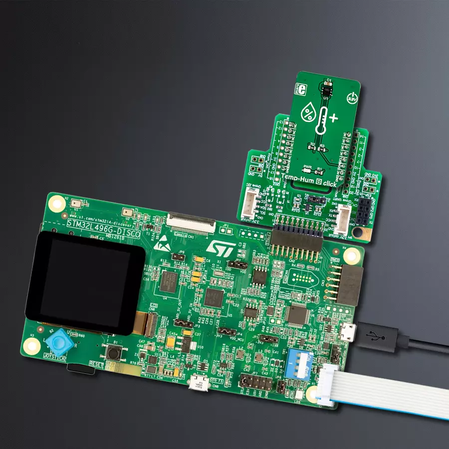
Step by step
Project assembly

Start by selecting your development board and Click board™. Begin with the Discovery kit with STM32L496AG MCU as your development board.


Software Support
Library Description
This library contains API for Temp&Hum 8 Click driver.
Key functions:
temphum8_get_temperature_data- Temperature datatemphum8_get_humidity_data- Relative Huminidy datatemphum8_set_cfg_register- Configuration device for measurement
Open Source
Code example
The complete application code and a ready-to-use project are available through the NECTO Studio Package Manager for direct installation in the NECTO Studio. The application code can also be found on the MIKROE GitHub account.
/*!
 * \file
 * \brief TempHum8 Click example
 *
 * # Description
 * This demo-app shows the temperature measurement procedure using Temp&Hum 8 Click.
 *
 * The demo application is composed of two sections :
 *
 * ## Application Init
 * Configuring Clicks and log objects.
 * Setting the Click in the default configuration to start the measurement,
 * and before that call function software_reset().
 *
 * ## Application Task
 * Reads ambient temperature data and Relative Huminidy data,
 * this data logs to USBUART every 1500ms.
 *
 * \author Katarina Perendic
 *
 */
// ------------------------------------------------------------------- INCLUDES

#include "board.h"
#include "log.h"
#include "temphum8.h"

// ------------------------------------------------------------------ VARIABLES

static temphum8_t temphum8;
static log_t logger;

// ------------------------------------------------------ APPLICATION FUNCTIONS

void application_init ( void )
{
    log_cfg_t log_cfg;
    temphum8_cfg_t cfg;

    /**
     * Logger initialization.
     * Default baud rate: 115200
     * Default log level: LOG_LEVEL_DEBUG
     * @note If USB_UART_RX and USB_UART_TX
     * are defined as HAL_PIN_NC, you will
     * need to define them manually for log to work.
     * See @b LOG_MAP_USB_UART macro definition for detailed explanation.
     */
    LOG_MAP_USB_UART( log_cfg );
    log_init( &logger, &log_cfg );
    log_info( &logger, "---- Application Init ----" );

    //  Click initialization.

    temphum8_cfg_setup( &cfg );
    TEMPHUM8_MAP_MIKROBUS( cfg, MIKROBUS_1 );
    temphum8_init( &temphum8, &cfg );

    temphum8_software_reset( &temphum8 );
    temphum8_default_cfg( &temphum8 );
}

void application_task ( void )
{
    float temperature;
    float humidity;

    //  Task implementation.

    log_printf( &logger, "\r\n ---- Ambient data ----\r\n" );

    temperature = temphum8_get_temperature_data( &temphum8, TEMPHUM8_TEMPERATURE_IN_CELSIUS );
    log_printf( &logger, "** Temperature: %.2f °C \r\n", temperature );

    humidity = temphum8_get_humidity_data( &temphum8 );
    log_printf( &logger, "** Humidity: %.2f %%RH \r\n", humidity );

    Delay_ms ( 1000 );
    Delay_ms ( 500 );
}

int main ( void )
{
    /* Do not remove this line or clock might not be set correctly. */
    #ifdef PREINIT_SUPPORTED
    preinit();
    #endif

    application_init( );

    for ( ; ; )
    {
        application_task( );
    }

    return 0;
}

// ------------------------------------------------------------------------ END
Additional Support
Resources
Category:Temperature & humidity


