Monitor and signal temperature changes with TMP144 and dsPIC33EP512MU810
Master of temperature observation
Published Mar 11, 2023
Click board™
Thermo 23 Click
Dev. board
Clicker 2 for dsPIC33
Compiler
NECTO Studio
MCU
dsPIC33EP512MU810
Digital temperature sensor with highly accurate and reliable results
A
A
Hardware Overview
How does it work?
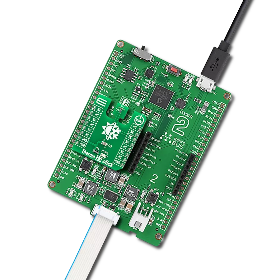
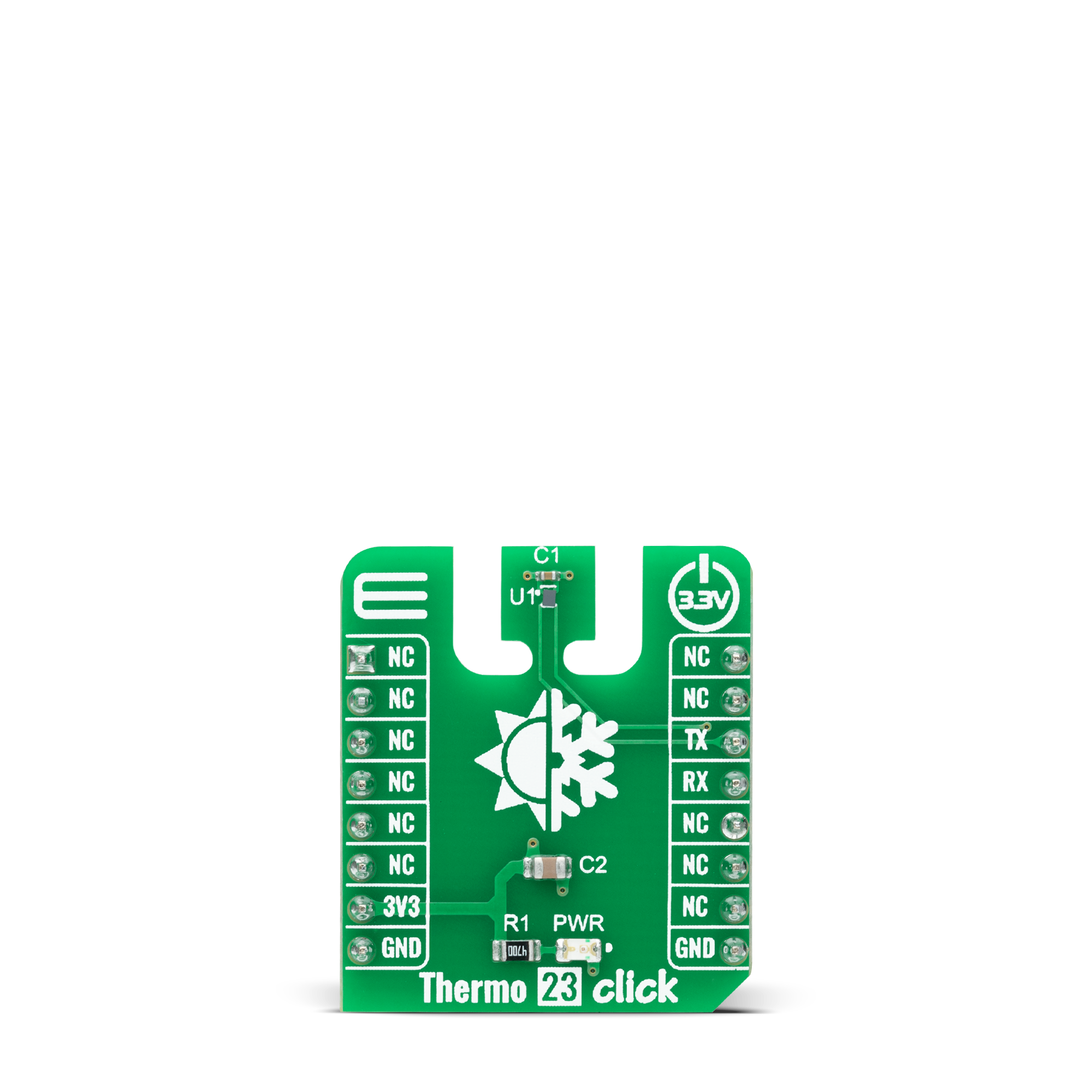
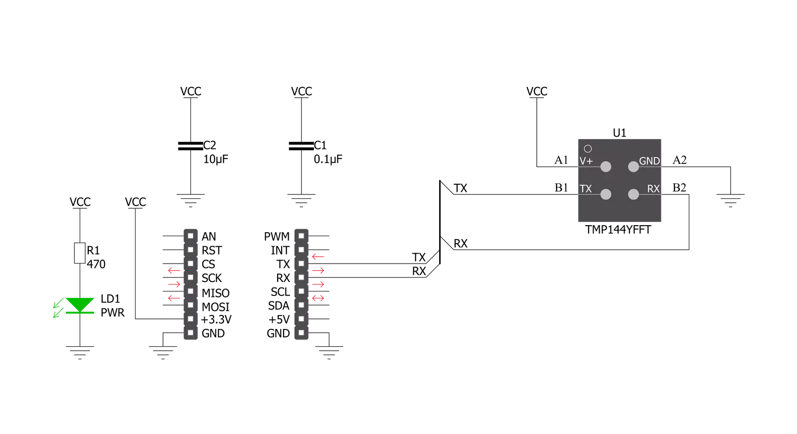
Thermo 23 Click is based on the TMP144, a digital temperature sensor that is optimal for thermal management and profiling applications from Texas Instruments. This temperature sensor is characterized by high accuracy; a temperature range of -10°C to +100°C provides typical ±0.5°C accuracy. The temperature sensing device for the TMP144 is the chip itself. A bipolar junction transistor inside the chip is used in a band-gap configuration to produce a voltage proportional to the chip temperature. The voltage is digitized and converted to a 12-bit temperature result in degrees Celsius, with a resolution of 0.0625°C. The TMP144 possesses several operational modes: Continuous-Conversion mode (CC), Shutdown, One-shot mode, and Extended Temperature mode, which increases the temperature-measurement range from -40°C to +120°C. In the CC mode, ADC performs continuous temperature conversions
and stores each result to the temperature register, overwriting the result from the previous conversion, while Shutdown modes reduce power consumption in the TMP75C when continuous temperature monitoring is not required, typically less than 0.5μA. Also, while the TMP144 is in Shutdown mode, it can perform a one-shot temperature measurement and return to the Shutdown state after the single conversion. Thermo 23 Click communicates with MCU using the UART interface with commonly used UART RX and TX pins as its communication protocol operating at 115200bps by default configuration to transmit and exchange data with the host MCU. This interface can also be seen as both UART and SMAART Wire™ interface, supporting daisy-chain configurations. Besides, the interface also supports Multiple Device Access (MDA) commands that let the host communicate with multiple devices on the bus simultaneously.
This sensor's special and equally important feature is its software interrupt, a temperature alert function that monitors the device temperature and compares the result to the values stored in the temperature limit registers to determine if the device temperature is within these set limits. The TMP144 only issues future interrupts once the user-writes sets the interrupt enable bit in the configuration register to re-enable future interrupts. This Click board™ can only be operated with a 3.3V logic voltage level. The board must perform appropriate logic voltage level conversion before using MCUs with different logic levels. However, the Click board™ comes equipped with a library containing functions and an example code that can be used as a reference for further development.
Features overview
Development board
Clicker 2 for dsPIC33 is a compact starter development board that brings the flexibility of add-on Click boards™ to your favorite microcontroller, making it a perfect starter kit for implementing your ideas. It comes with an onboard 16-bit dsPIC33E family microcontroller, the dsPIC33EP512MU810 from Microchip, two mikroBUS™ sockets for Click board™ connectivity, a USB connector, LED indicators, buttons, a mikroProg programmer connector, and two 26-pin headers for interfacing with external electronics. Its compact design with clear and easily recognizable silkscreen markings allows you to build gadgets with unique
functionalities and features quickly. Each part of the Clicker 2 for dsPIC33 development kit contains the components necessary for the most efficient operation of the same board. In addition to the possibility of choosing the Clicker 2 for dsPIC33 programming method, using a USB HID mikroBootloader or an external mikroProg connector for dsPIC33 programmer, the Clicker 2 board also includes a clean and regulated power supply module for the development kit. It provides two ways of board-powering; through the USB Micro-B cable, where onboard voltage regulators provide the appropriate voltage levels to each
component on the board, or using a Li-Polymer battery via an onboard battery connector. All communication methods that mikroBUS™ itself supports are on this board, including the well-established mikroBUS™ socket, reset button, and several user-configurable buttons and LED indicators. Clicker 2 for dsPIC33 is an integral part of the Mikroe ecosystem, allowing you to create a new application in minutes. Natively supported by Mikroe software tools, it covers many aspects of prototyping thanks to a considerable number of different Click boards™ (over a thousand boards), the number of which is growing every day.

Microcontroller Overview
MCU Card / MCU
Architecture
dsPIC
MCU Memory (KB)
512
Silicon Vendor
Microchip
Pin count
100
RAM (Bytes)
53248
Used MCU Pins
mikroBUS™ mapper
Take a closer look
Click board™ Schematic
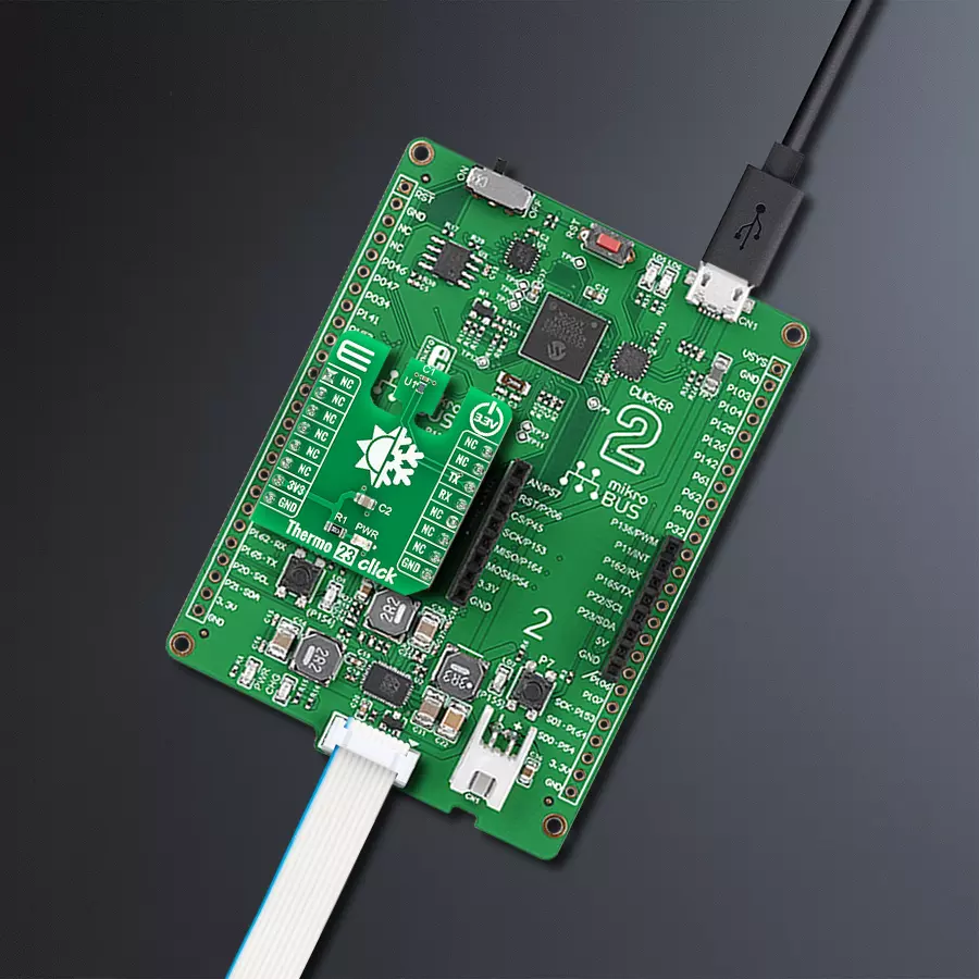
Step by step
Project assembly

Start by selecting your development board and Click board™. Begin with the Clicker 2 for dsPIC33 as your development board.


Software Support
Library Description
This library contains API for Thermo 23 Click driver.
Key functions:
thermo23_set_configThis function sets the configuration register.thermo23_read_temperatureThis function reads the temperature value in Celsius.thermo23_read_commandThis function reads data from the selected command by using UART serial interface.
Open Source
Code example
The complete application code and a ready-to-use project are available through the NECTO Studio Package Manager for direct installation in the NECTO Studio. The application code can also be found on the MIKROE GitHub account.
/*!
 * @file main.c
 * @brief Thermo 23 Click Example.
 *
 * # Description
 * This example demonstrates the use of Thermo 23 Click board by reading and displaying
 * the temperature measurements.
 *
 * The demo application is composed of two sections :
 *
 * ## Application Init
 * Initializes the driver and logger, and performs the Click default configuration which enables
 * continuous conversion and sets the conversion rate to 1 Hz.
 *
 * ## Application Task
 * Reads the temperature measurement in Celsius and displays the results on the USB UART
 * approximately once per second.
 *
 * @author Stefan Filipovic
 *
 */

#include "board.h"
#include "log.h"
#include "thermo23.h"

static thermo23_t thermo23;
static log_t logger;

void application_init ( void )
{
    log_cfg_t log_cfg;  /**< Logger config object. */
    thermo23_cfg_t thermo23_cfg;  /**< Click config object. */

    /**
     * Logger initialization.
     * Default baud rate: 115200
     * Default log level: LOG_LEVEL_DEBUG
     * @note If USB_UART_RX and USB_UART_TX
     * are defined as HAL_PIN_NC, you will
     * need to define them manually for log to work.
     * See @b LOG_MAP_USB_UART macro definition for detailed explanation.
     */
    LOG_MAP_USB_UART( log_cfg );
    log_init( &logger, &log_cfg );
    log_info( &logger, " Application Init " );

    // Click initialization.
    thermo23_cfg_setup( &thermo23_cfg );
    THERMO23_MAP_MIKROBUS( thermo23_cfg, MIKROBUS_1 );
    if ( UART_ERROR == thermo23_init( &thermo23, &thermo23_cfg ) )
    {
        log_error( &logger, " Communication init." );
        for ( ; ; );
    }

    if ( THERMO23_ERROR == thermo23_default_cfg ( &thermo23 ) )
    {
        log_error( &logger, " Default configuration." );
        for ( ; ; );
    }

    log_info( &logger, " Application Task " );
}

void application_task ( void )
{
    float temperature;
    if ( THERMO23_OK == thermo23_read_temperature ( &thermo23, &temperature ) )
    {
        log_printf( &logger, " Temperature : %.2f C\r\n\n", temperature );
        Delay_ms ( 1000 );
    }
}

int main ( void )
{
    /* Do not remove this line or clock might not be set correctly. */
    #ifdef PREINIT_SUPPORTED
    preinit();
    #endif

    application_init( );

    for ( ; ; )
    {
        application_task( );
    }

    return 0;
}

// ------------------------------------------------------------------------ END
Additional Support
Resources
Category:Temperature & humidity


