Build a mobile RTK Rover station with LG69TAMMD and PIC18F47Q10
Achieve centimeter-precise position
Published Mar 01, 2023
Click board™
RTK Rover Click
Dev. board
Curiosity HPC
Compiler
NECTO Studio
MCU
PIC18F47Q10
Enhance the position-data precision of compatible RTK Base Station
A
A
Hardware Overview
How does it work?
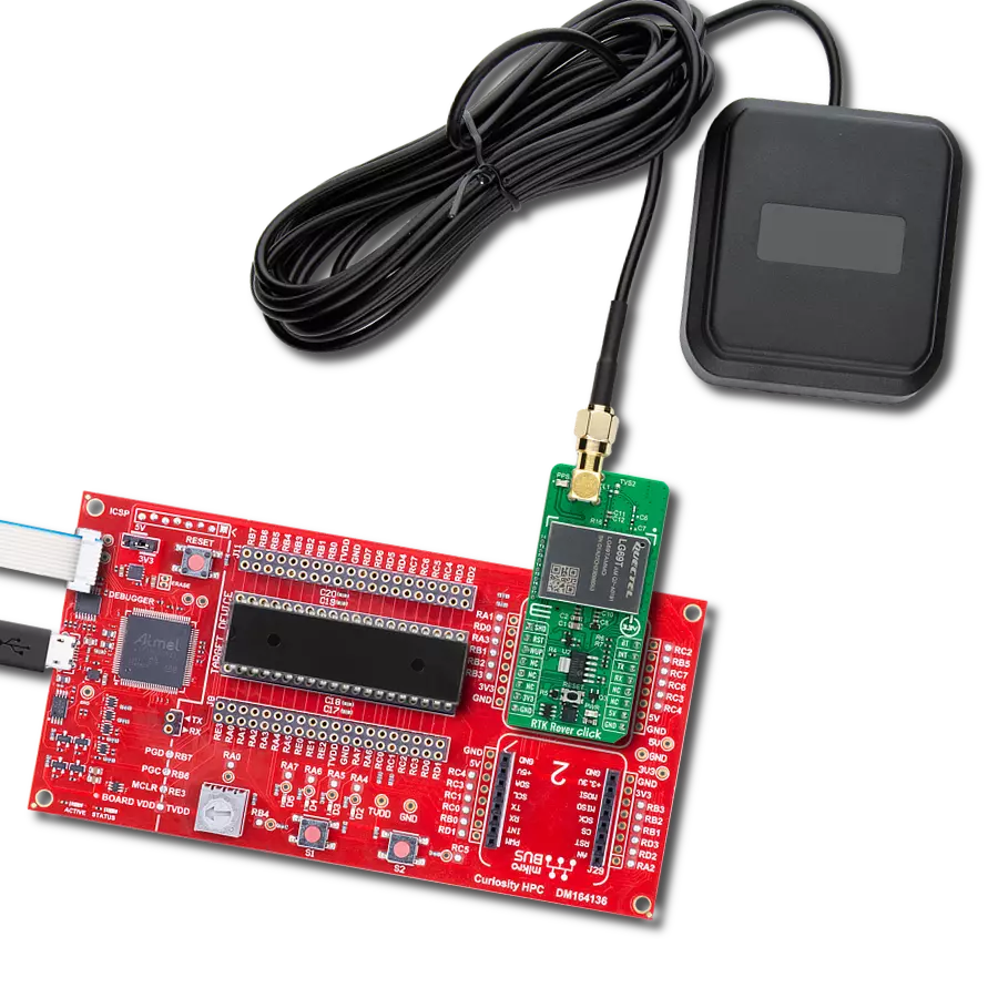
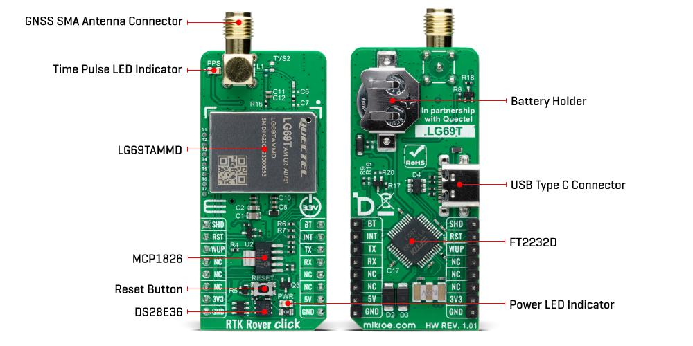
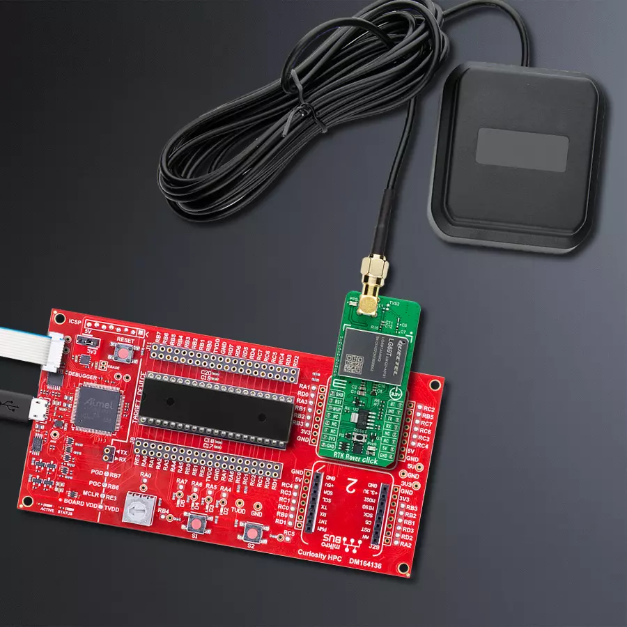
RTK Rover Click is based on the LG69TAMMD, a multi-constellation GNSS module featuring a high-performance and high-reliability positioning engine from Quectel Wireless Solutions that facilitates a fast and precise GNSS positioning capability. The LG69TAMMD has a dual-band supporting up to three concurrent global constellations featuring STMicroelectronics®' fifth-generation positioning receiver platform with 80 tracking and four fast acquisition channels. It is characterized by a horizontal position accuracy of 1m autonomous (24h static) and 0.01m+1ppm RTK with a high-performance YB0017AA mobile antenna in an open-sky environment and within 1km of the base station. The primary function of the LG69TAMMD is PVT (RTK) which stands for Position, Velocity, and Time. Designed according to the IATF 16949:2016 standard, the LG69TAMMD has GPS+BDS+Galileo as a default GNSS constellation and an integrated LNA for improved sensitivity. It can receive and track GPS L1 C/A and L5 and Galileo E1 and E5a signals centered at 1575.42MHz and 1176.45MHz, and BeiDou B1I and B2a signals centered at 1561.098MHz and 1176.45MHz. The ability to receive and track BeiDou signals with GPS results in higher coverage, improved reliability, and better accuracy. RTK Rover Click communicates with an MCU using the
UART interface, with commonly-used RX and TX pins alongside one data-ready pin (INT), which informs the host MCU to receive data when the buffer transmission is full. It is also equipped with a USB type C connector, which allows the module to be powered and configured by a personal computer (PC) using FT2232D, a compact USB to a serial UART interface device designed to operate efficiently with USB host controllers. Before supporting the RTK navigation technique, this module must receive the RTK correction messages via its UART port. In a default configuration, it will attempt to achieve the best positioning accuracy based on the correction data it receives. When the module receives an input stream of RTCM messages, it will enter RTK float mode, and once it fixes carrier phase ambiguities, it enters RTK fixed mode. It will typically take less than 60 seconds before the Rover can solve the carrier ambiguities and go from RTK float to RTK fixed mode. In addition to the interface pins, this board uses a few additional mikroBUS™ pins. An active-low reset signal alongside an onboard RESET button, routed on the RST pin of the mikroBUS™ socket, performs a reset function of the module. The WUP pin performs module wake-up, and the SHD pin routed on the AN pin of the mikroBUS™ socket offers a switch operation to
turn ON/OFF the power supply to the LG69TAMMD. The module can use Boot Download Mode for firmware update via the BT pin routed on the RST pin of the mikroBUS™ socket, alongside a blue LED indicator marked as PPS for time pulse signal information and indication. The module enters Normal operating mode by keeping the BT pin on a low logic state during the Startup sequence. Otherwise, the module enters Boot Download Mode when the pin is high during Startup. A specific addition to this Click board™ is several testpoints that enable additional module features such as RTK positioning status indicator, Wheel tick pulse signal sampled from the wheel revolution sensors, or correction UART by default or NMEA output/raw data output. This Click board™ can operate with both 3.3V and 5V MCUs. As its main power supply, the LG69TAMMD uses 3.3V obtained from the MCP1826 LDO but can also use an additional backup power supply in the form of a coin-shaped battery. The board must perform appropriate logic voltage level conversion before using MCUs with different logic levels. However, the Click board™ comes equipped with a library containing functions and an example code that can be used as a reference for further development.
Features overview
Development board
Curiosity HPC, standing for Curiosity High Pin Count (HPC) development board, supports 28- and 40-pin 8-bit PIC MCUs specially designed by Microchip for the needs of rapid development of embedded applications. This board has two unique PDIP sockets, surrounded by dual-row expansion headers, allowing connectivity to all pins on the populated PIC MCUs. It also contains a powerful onboard PICkit™ (PKOB), eliminating the need for an external programming/debugging tool, two mikroBUS™ sockets for Click board™ connectivity, a USB connector, a set of indicator LEDs, push button switches and a variable potentiometer. All
these features allow you to combine the strength of Microchip and Mikroe and create custom electronic solutions more efficiently than ever. Each part of the Curiosity HPC development board contains the components necessary for the most efficient operation of the same board. An integrated onboard PICkit™ (PKOB) allows low-voltage programming and in-circuit debugging for all supported devices. When used with the MPLAB® X Integrated Development Environment (IDE, version 3.0 or higher) or MPLAB® Xpress IDE, in-circuit debugging allows users to run, modify, and troubleshoot their custom software and hardware
quickly without the need for additional debugging tools. Besides, it includes a clean and regulated power supply block for the development board via the USB Micro-B connector, alongside all communication methods that mikroBUS™ itself supports. Curiosity HPC development board allows you to create a new application in just a few steps. Natively supported by Microchip software tools, it covers many aspects of prototyping thanks to many number of different Click boards™ (over a thousand boards), the number of which is growing daily.

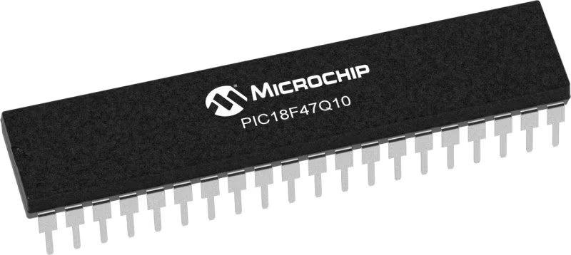
Microcontroller Overview
MCU Card / MCU
Architecture
PIC
MCU Memory (KB)
128
Silicon Vendor
Microchip
Pin count
40
RAM (Bytes)
3615
You complete me!
Accessories
GNSS L1/L5 Active External Antenna (YB0017AA) is an active patch antenna from Quectel that supports GNSS L1/L5 BD B1/B2 GLONASS L1, offering excellent performance with its high gain and efficiency for fleet management, navigation, RTK, and many other tracking applications. The magnetic-mounting antenna, with dimensions of 61.5×56.5×23mm, is designed to work with various ground plane sizes or in free space and is connected to the device by a 3m cable with an SMA male connector.

Used MCU Pins
mikroBUS™ mapper
Take a closer look
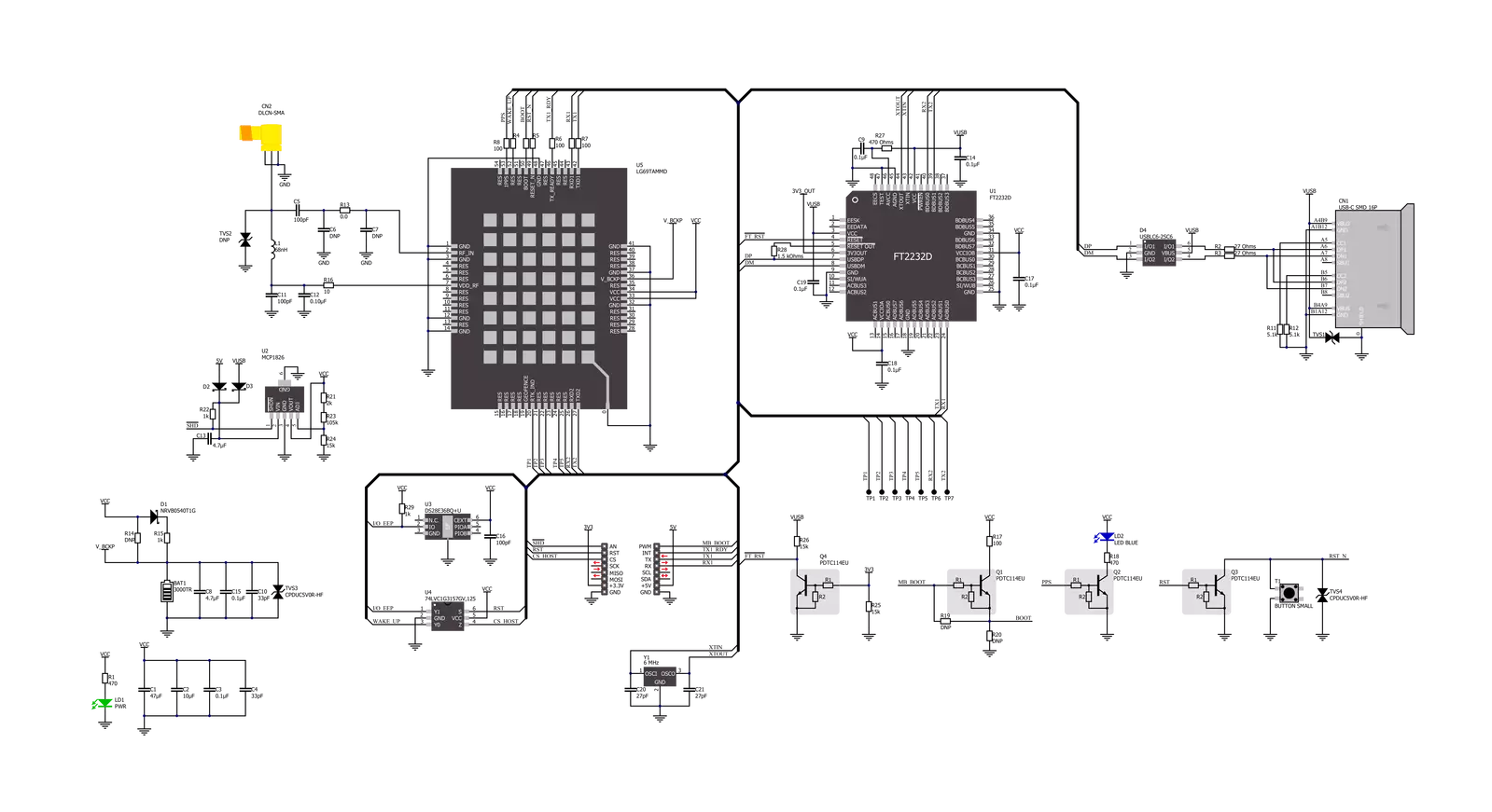
Click board™ Schematic
Step by step
Project assembly

Start by selecting your development board and Click board™. Begin with the Curiosity HPC as your development board.


Track your results in real time
Application Output
1. Application Output - In Debug mode, the 'Application Output' window enables real-time data monitoring, offering direct insight into execution results. Ensure proper data display by configuring the environment correctly using the provided tutorial.

2. UART Terminal - Use the UART Terminal to monitor data transmission via a USB to UART converter, allowing direct communication between the Click board™ and your development system. Configure the baud rate and other serial settings according to your project's requirements to ensure proper functionality. For step-by-step setup instructions, refer to the provided tutorial.

3. Plot Output - The Plot feature offers a powerful way to visualize real-time sensor data, enabling trend analysis, debugging, and comparison of multiple data points. To set it up correctly, follow the provided tutorial, which includes a step-by-step example of using the Plot feature to display Click board™ readings. To use the Plot feature in your code, use the function: plot(*insert_graph_name*, variable_name);. This is a general format, and it is up to the user to replace 'insert_graph_name' with the actual graph name and 'variable_name' with the parameter to be displayed.

Software Support
Library Description
This library contains API for RTK Rover Click driver.
Key functions:
rtkrover_generic_readThis function reads a desired number of data bytes by using UART serial interface.rtkrover_clear_ring_buffersThis function clears UART tx and rx ring buffers.rtkrover_parse_gnggaThis function parses the GNGGA data from the read response buffer.
Open Source
Code example
The complete application code and a ready-to-use project are available through the NECTO Studio Package Manager for direct installation in the NECTO Studio. The application code can also be found on the MIKROE GitHub account.
/*!
 * @file main.c
 * @brief RTK Rover Click Example.
 *
 * # Description
 * This example demonstrates the use of RTK Rover Click by reading and displaying
 * the GPS coordinates.
 *
 * The demo application is composed of two sections :
 *
 * ## Application Init
 * Initializes the driver and logger.
 *
 * ## Application Task
 * Reads the received data, parses the GNGGA info from it, and once it receives the position fix
 * it will start displaying the coordinates on the USB UART.
 *
 * ## Additional Function
 * - static void rtkrover_clear_app_buf ( void )
 * - static err_t rtkrover_process ( rtkrover_t *ctx )
 * - static void rtkrover_parser_application ( char *rsp )
 *
 * @note
 * The Click board comes with the default baud rate of 460800, but the baud rate is set to 115200
 * in the example due to code portability and speed limitations of some MCUs. So in order to run
 * the example you will need to adjust the baud rate using Quectel QGNSS evaluation software.
 *
 * @author Stefan Filipovic
 *
 */

#include "board.h"
#include "log.h"
#include "rtkrover.h"
#include "string.h"

#define PROCESS_BUFFER_SIZE 200

static rtkrover_t rtkrover;
static log_t logger;

static char app_buf[ PROCESS_BUFFER_SIZE ] = { 0 };
static int32_t app_buf_len = 0;

/**
 * @brief RTK Rover clearing application buffer.
 * @details This function clears memory of application buffer and reset its length.
 * @return None.
 * @note None.
 */
static void rtkrover_clear_app_buf ( void );

/**
 * @brief RTK Rover data reading function.
 * @details This function reads data from device and concatenates data to application buffer.
 * @param[in] ctx : Click context object.
 * See #rtkrover_t object definition for detailed explanation.
 * @return @li @c  0 - Read some data.
 *         @li @c -1 - Nothing is read.
 * See #err_t definition for detailed explanation.
 * @note None.
 */
static err_t rtkrover_process ( rtkrover_t *ctx );

/**
 * @brief RTK Rover parser application function.
 * @details This function parses GNSS data and logs it on the USB UART. It clears app and ring buffers
 * after successfully parsing data.
 * @param[in] ctx : Click context object.
 * See #rtkrover_t object definition for detailed explanation.
 * @param[in] rsp Response buffer.
 * @return None.
 * @note None.
 */
static void rtkrover_parser_application ( rtkrover_t *ctx, char *rsp );

void application_init ( void )
{
    log_cfg_t log_cfg;  /**< Logger config object. */
    rtkrover_cfg_t rtkrover_cfg;  /**< Click config object. */

    /**
     * Logger initialization.
     * Default baud rate: 115200
     * Default log level: LOG_LEVEL_DEBUG
     * @note If USB_UART_RX and USB_UART_TX
     * are defined as HAL_PIN_NC, you will
     * need to define them manually for log to work.
     * See @b LOG_MAP_USB_UART macro definition for detailed explanation.
     */
    LOG_MAP_USB_UART( log_cfg );
    log_init( &logger, &log_cfg );
    log_info( &logger, " Application Init " );

    // Click initialization.
    rtkrover_cfg_setup( &rtkrover_cfg );
    RTKROVER_MAP_MIKROBUS( rtkrover_cfg, MIKROBUS_1 );
    if ( UART_ERROR == rtkrover_init( &rtkrover, &rtkrover_cfg ) )
    {
        log_error( &logger, " Communication init." );
        for ( ; ; );
    }
    log_info( &logger, " Application Task " );
}

void application_task ( void )
{
    if ( RTKROVER_OK == rtkrover_process( &rtkrover ) )
    {
        if ( PROCESS_BUFFER_SIZE == app_buf_len )
        {
            rtkrover_parser_application( &rtkrover, app_buf );
        }
    }
}

int main ( void )
{
    /* Do not remove this line or clock might not be set correctly. */
    #ifdef PREINIT_SUPPORTED
    preinit();
    #endif

    application_init( );

    for ( ; ; )
    {
        application_task( );
    }

    return 0;
}

static void rtkrover_clear_app_buf ( void )
{
    memset( app_buf, 0, app_buf_len );
    app_buf_len = 0;
}

static err_t rtkrover_process ( rtkrover_t *ctx )
{
    char rx_buf[ PROCESS_BUFFER_SIZE ] = { 0 };
    int32_t rx_size = 0;
    rx_size = rtkrover_generic_read( ctx, rx_buf, PROCESS_BUFFER_SIZE );
    if ( rx_size > 0 )
    {
        int32_t buf_cnt = app_buf_len;
        if ( ( ( app_buf_len + rx_size ) > PROCESS_BUFFER_SIZE ) && ( app_buf_len > 0 ) )
        {
            buf_cnt = PROCESS_BUFFER_SIZE - ( ( app_buf_len + rx_size ) - PROCESS_BUFFER_SIZE );
            memmove ( app_buf, &app_buf[ PROCESS_BUFFER_SIZE - buf_cnt ], buf_cnt );
        }
        for ( int32_t rx_cnt = 0; rx_cnt < rx_size; rx_cnt++ )
        {
            if ( rx_buf[ rx_cnt ] )
            {
                app_buf[ buf_cnt++ ] = rx_buf[ rx_cnt ];
                if ( app_buf_len < PROCESS_BUFFER_SIZE )
                {
                    app_buf_len++;
                }
            }
        }
        return RTKROVER_OK;
    }
    return RTKROVER_ERROR;
}

static void rtkrover_parser_application ( rtkrover_t *ctx, char *rsp )
{
    char element_buf[ 100 ] = { 0 };
    if ( RTKROVER_OK == rtkrover_parse_gngga( rsp, RTKROVER_GNGGA_LATITUDE, element_buf ) )
    {
        static uint8_t wait_for_fix_cnt = 0;
        if ( strlen( element_buf ) > 0 )
        {
            log_printf( &logger, "\r\n Latitude: %.2s degrees, %s minutes \r\n", element_buf, &element_buf[ 2 ] );
            rtkrover_parse_gngga( rsp, RTKROVER_GNGGA_LONGITUDE, element_buf );
            log_printf( &logger, " Longitude: %.3s degrees, %s minutes \r\n", element_buf, &element_buf[ 3 ] );
            memset( element_buf, 0, sizeof( element_buf ) );
            rtkrover_parse_gngga( rsp, RTKROVER_GNGGA_ALTITUDE, element_buf );
            log_printf( &logger, " Altitude: %s m \r\n", element_buf );
            wait_for_fix_cnt = 0;
            Delay_ms ( 1000 );
        }
        else
        {
            if ( wait_for_fix_cnt % 20 == 0 )
            {
                log_printf( &logger, " Waiting for the position fix...\r\n\n" );
                wait_for_fix_cnt = 0;
            }
            wait_for_fix_cnt++;
        }
        rtkrover_clear_ring_buffers( ctx );
        rtkrover_clear_app_buf( );
    }
}

// ------------------------------------------------------------------------ END
Additional Support
Resources
Category:GPS/GNSS


