Make your GPS tracking device with M20050-1 and STM32F407VGT6
Your beacon of navigation!

Published Apr 04, 2023
Click board™
GPS 5 Click
Dev. board
EasyMx PRO v7a for STM32
Compiler
NECTO Studio
MCU
STM32F407VGT6
Stay connected to the world around you and find your way with ease
A
A
Hardware Overview
How does it work?
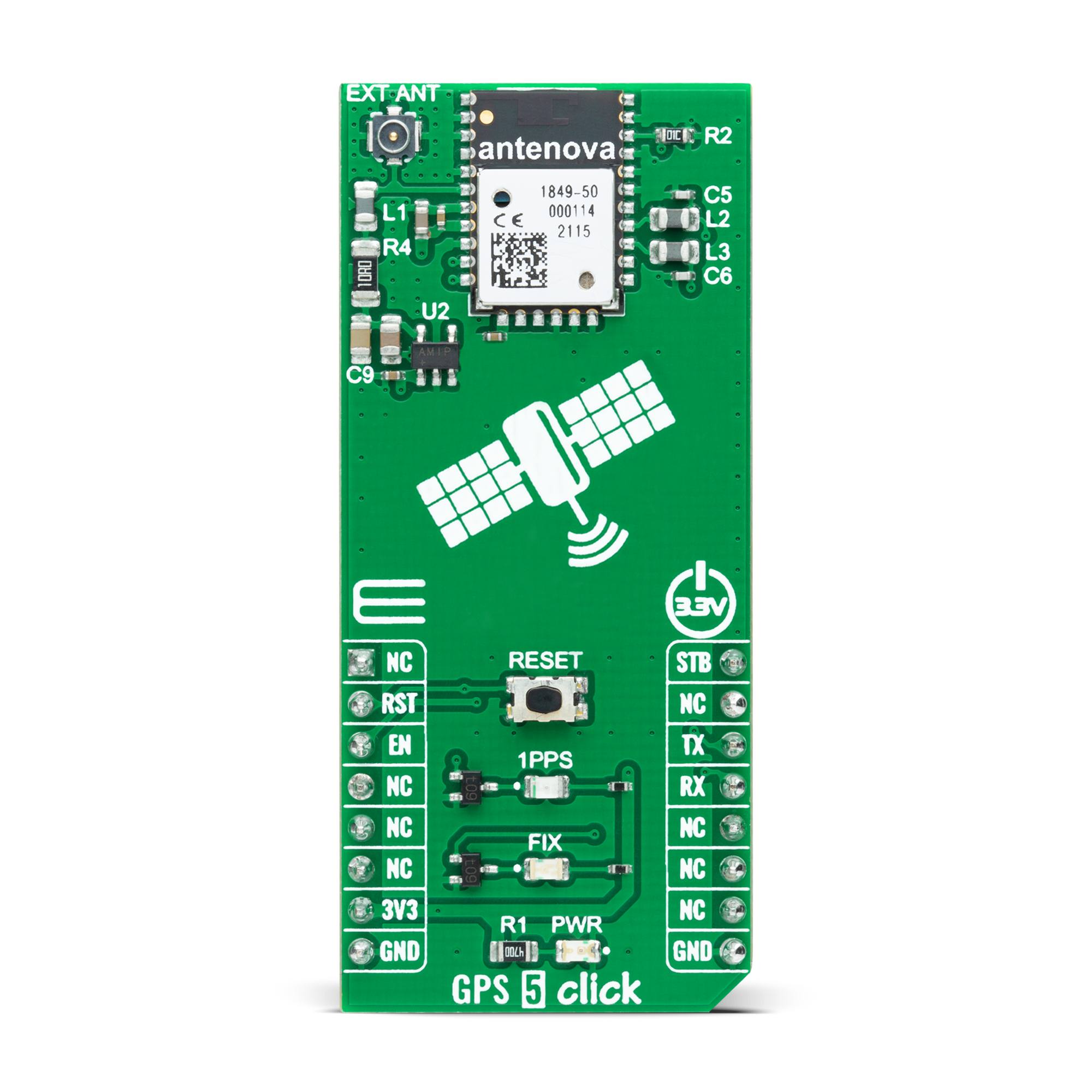
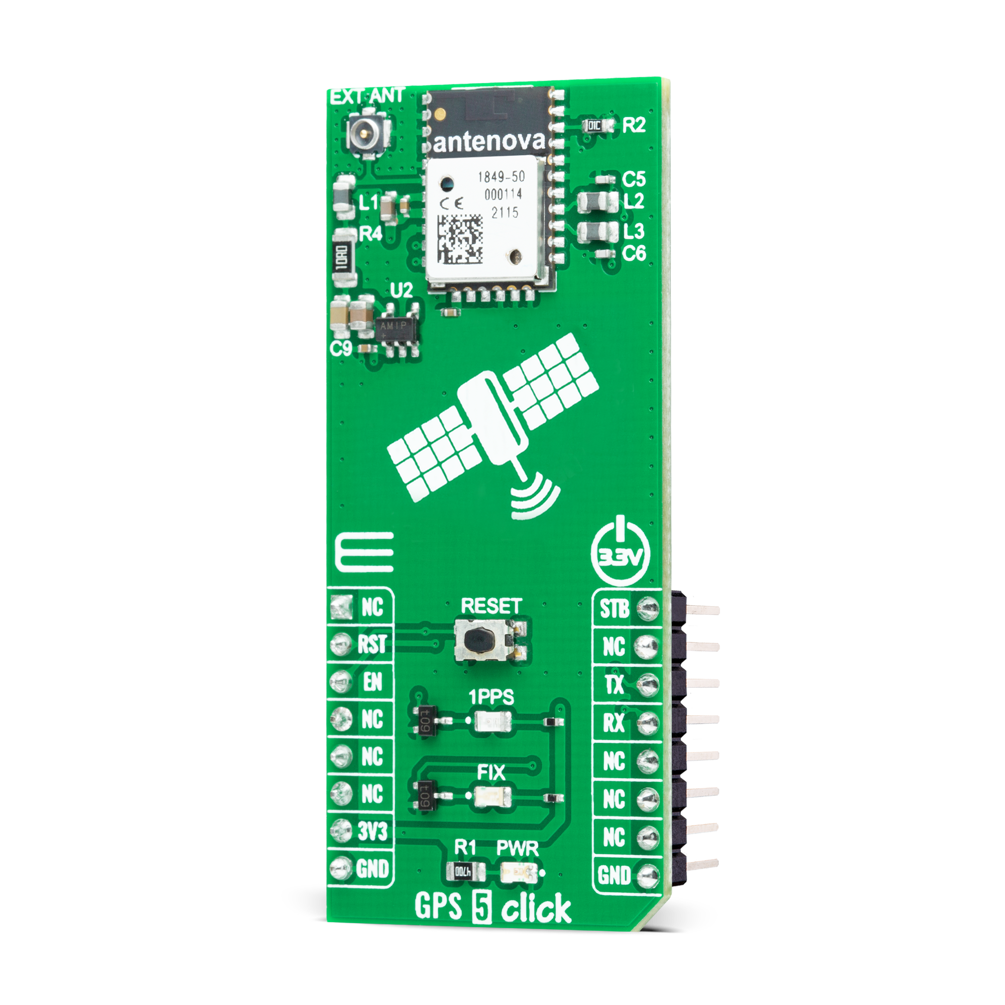
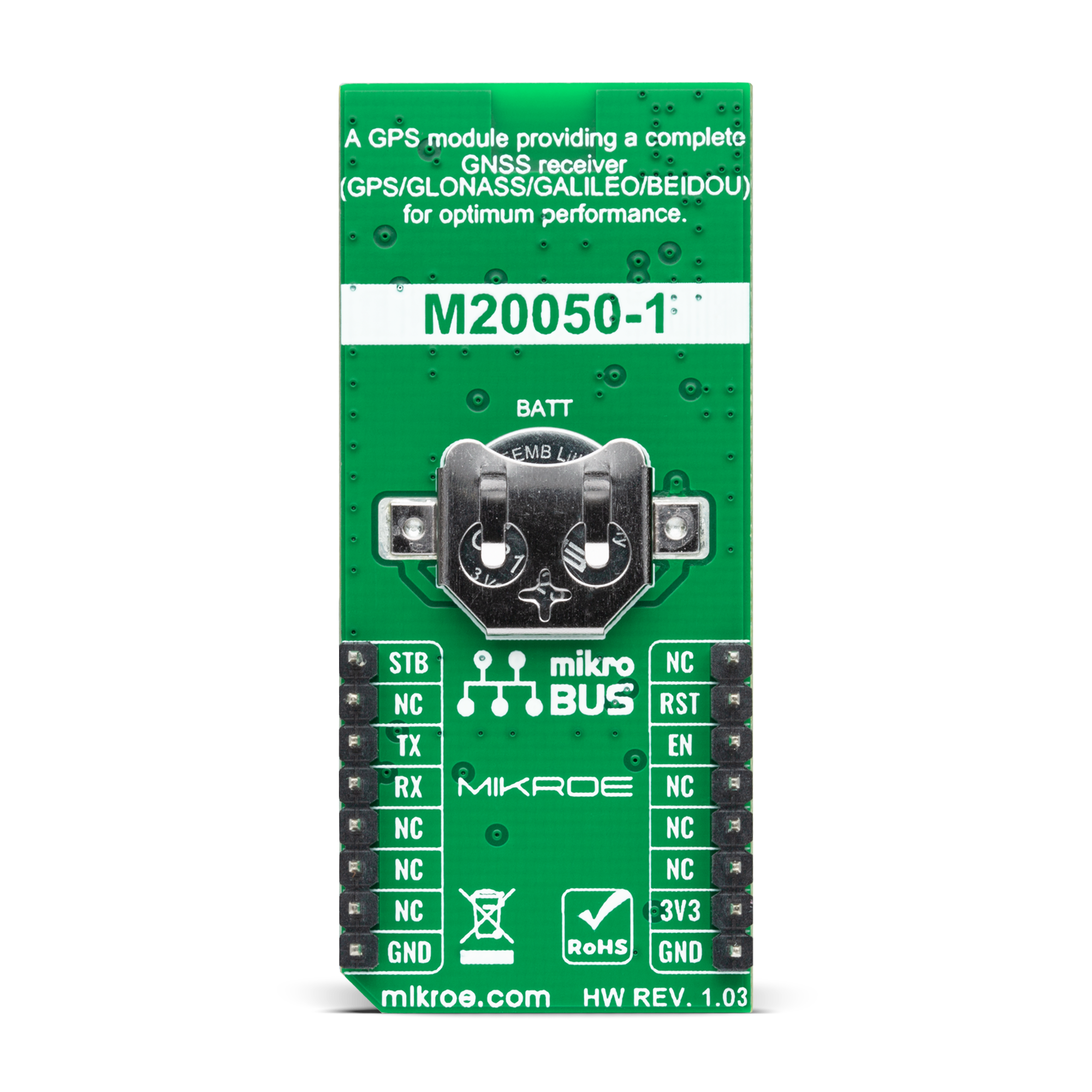
GPS 5 Click is based on the M20050-1, an integrated GNSS receiver module with an integrated antenna incorporating the MediaTek MT3333 flash chip from Antenova. The M20050-1 tracks 3 GNSS constellations concurrently (GPS+Galileo+GLONASS or GPS+Beidou) to considerably enhance the location and has configurable low power modes alongside acquisition and tracking sensitivity of -163dBm and -165dBm. This module offers indoor and outdoor multi-path detection and compensation and has an accurate 0.5ppm TXCO that ensures short TTFF besides an active interference cancellation (AIC) feature. This Click board is ideal for asset tracking/ personal safety, navigation devices, and sports equipment applications based on good attributes. The M20050-1 has three power-saving modes: Standby, Backup, and Periodic. Standby mode is a power-saving mode initiated with a hardware signal routed on the STB pin of the mikroBUS™ socket or by a software command.
It shuts down the RF section of the module, putting the processor into Standby mode. The RTC is kept alive, and the RAM power is maintained to keep the module configuration. Periodic mode is a user-configurable mode that reduces current consumption by only waking the module for short periods to maintain FIX data. Backup mode is accessed due to the absence of the main board power supply VCC. For this reason, there is an additional backup power supply in the form of a battery that powers the RAM and RTC sections of the receiver and needs to be applied at all times for Backup mode to run correctly. Once initiated, the RTC and all configurations are saved along with any ephemeris data to allow quick TTFF once the VCC is re-applied. GPS 5 Click communicates with MCU using the UART interface with commonly used UART RX and TX pins operating at 115200bps by default to transmit and exchange data with the host MCU. It also possesses an active-low reset signal routed on the
RST pin of the mikroBUS™ socket that activates a hardware reset of the M20050-1. The reset function can also be used using an onboard RESET button. In addition to precise positioning, the GPS 5 Click also has an accurate timing signal indicated via a red LED indicator marked as 1PPS, a blue LED indicator marked with FIX, which shows once a GPS fix has been obtained, as well as the possibility of using an external active antenna which can also be found in our offer, activated through EN pin of the mikroBUS™ socket. This Click board™ can only be operated with a 3.3V logic voltage level. The board must perform appropriate logic voltage level conversion before using MCUs with different logic levels. However, the Click board™ comes equipped with a library containing functions and an example code that can be used as a reference for further development.
Features overview
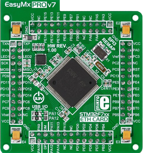
Development board
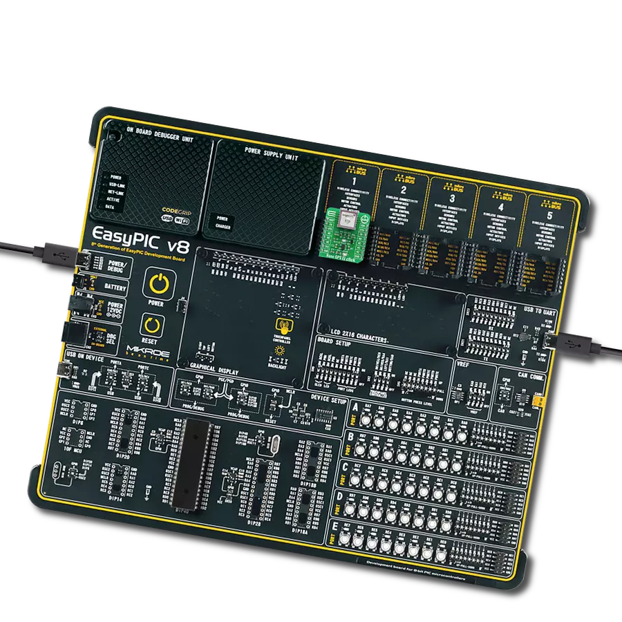
EasyMx PRO v7a for STM32 is the seventh generation of ARM development boards specially designed to develop embedded applications rapidly. It supports a wide range of 32-bit ARM microcontrollers from STMicroelectronics and a broad set of unique functions, such as the first-ever embedded debugger/programmer over USB-C. The development board is well organized and designed so that the end-user has all the necessary elements, such as switches, buttons, indicators, connectors, and others, in one place. With two different connectors for each port, EasyMx PRO v7afor STM32 allows you to connect accessory boards, sensors, and custom electronics more efficiently than ever. Each part of the EasyMx
PRO v7a for STM32 development board contains the components necessary for the most efficient operation of the same board. In addition to the advanced integrated CODEGRIP programmer/debugger module, which offers many valuable programming/debugging options and seamless integration with the Mikroe software environment, the board also includes a clean and regulated power supply block for the development board. It can use a wide range of external power sources, including an external 12V power supply, 7-23V AC or 9-32V DC via DC connector/screw terminals, and a power source via the USB Type-C (USB-C) connector. Communication options such as USB-UART, USB-HOST/DEVICE, CAN, and
Ethernet are also included, including the well-established mikroBUS™ standard, one display option for the TFT board line of products, and a standard TQFP socket for the seventh-generation MCU cards. This socket covers 32-bit ARM MCUs like STM32 Cortex-M3, -M7, and -M4 MCUs. EasyMx PRO v7afor STM32 is an integral part of the Mikroe ecosystem for rapid development. Natively supported by Mikroe software tools, it covers many aspects of prototyping and development thanks to a considerable number of different Click boards™ (over a thousand boards), the number of which is growing every day.

Microcontroller Overview
MCU Card / MCU
Type
7th Generation
Architecture
ARM Cortex-M4
MCU Memory (KB)
10
Silicon Vendor
STMicroelectronics
Pin count
100
RAM (Bytes)
192k
Used MCU Pins
mikroBUS™ mapper
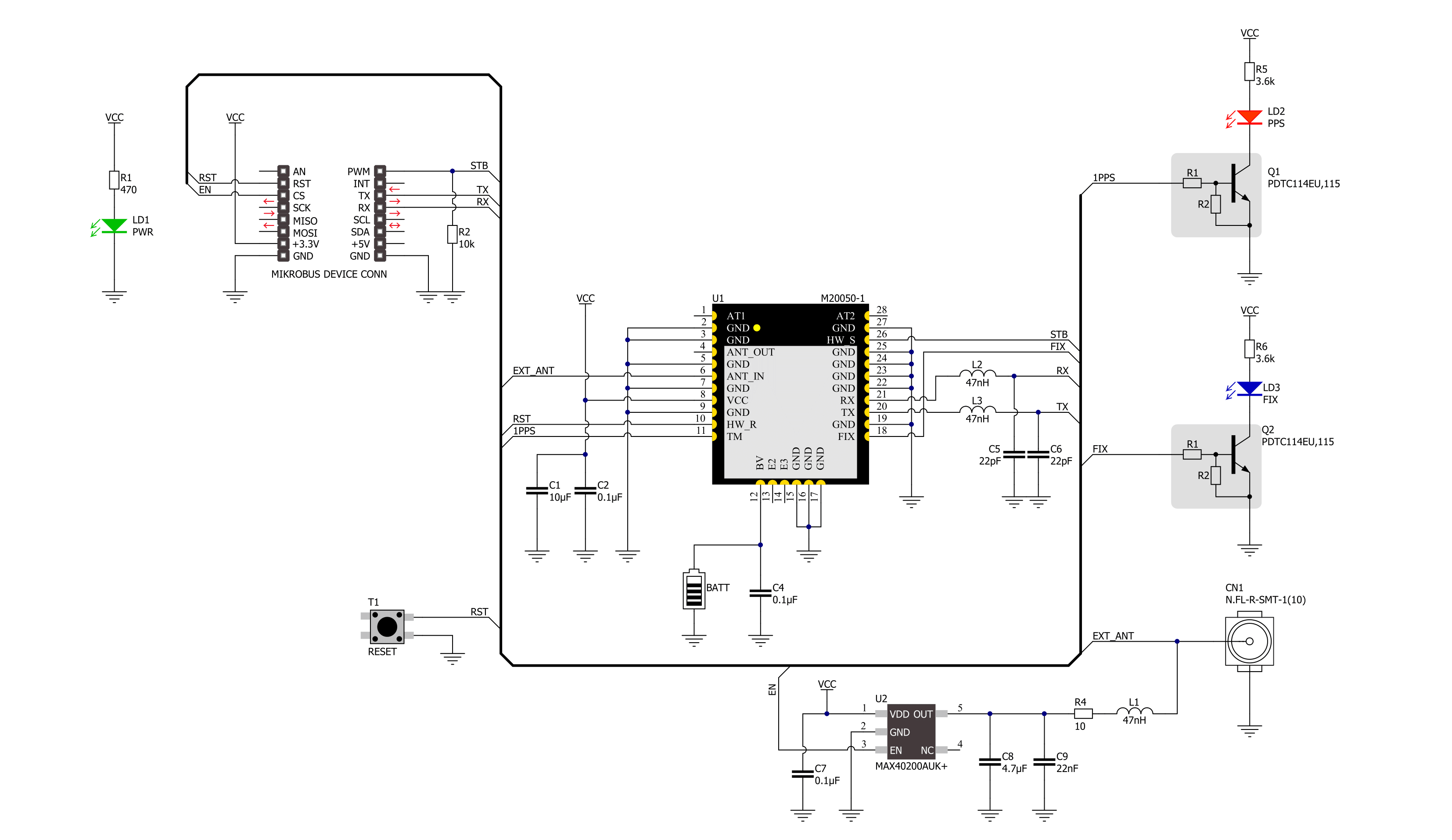
Take a closer look
Click board™ Schematic
Step by step
Project assembly

Start by selecting your development board and Click board™. Begin with the EasyMx PRO v7a for STM32 as your development board.


Software Support
Library Description
This library contains API for GPS 5 Click driver.
Key functions:
gps5_set_rst_pinThis function sets the RST pin logic state.gps5_generic_readThis function reads a desired number of data bytes by using UART serial interface.gps5_parse_gnggaThis function parses the GNGGA data from the read response buffer.
Open Source
Code example
The complete application code and a ready-to-use project are available through the NECTO Studio Package Manager for direct installation in the NECTO Studio. The application code can also be found on the MIKROE GitHub account.
/*!
 * @file main.c
 * @brief GPS 5 Click Example.
 *
 * # Description
 * This example demonstrates the use of GPS 5 Click by reading and displaying
 * the GPS coordinates.
 *
 * The demo application is composed of two sections :
 *
 * ## Application Init
 * Initializes the driver and resets the Click board.
 *
 * ## Application Task
 * Reads the received data, parses the GNGGA info from it, and once it receives the position fix
 * it will start displaying the coordinates on the USB UART.
 *
 * ## Additional Function
 * - static void gps5_clear_app_buf ( void )
 * - static err_t gps5_process ( gps5_t *ctx )
 * - static void gps5_parser_application ( char *rsp )
 *
 * @author Stefan Filipovic
 *
 */

#include "board.h"
#include "log.h"
#include "gps5.h"

#define PROCESS_BUFFER_SIZE 200

static gps5_t gps5;
static log_t logger;

static char app_buf[ PROCESS_BUFFER_SIZE ] = { 0 };
static int32_t app_buf_len = 0;
static int32_t app_buf_cnt = 0;

/**
 * @brief GPS 5 clearing application buffer.
 * @details This function clears memory of application buffer and reset its length and counter.
 * @return None.
 * @note None.
 */
static void gps5_clear_app_buf ( void );

/**
 * @brief GPS 5 data reading function.
 * @details This function reads data from device and concatenates data to application buffer.
 * @param[in] ctx : Click context object.
 * See #gps5_t object definition for detailed explanation.
 * @return @li @c  0 - Read some data.
 *         @li @c -1 - Nothing is read or Application buffer overflow.
 * See #err_t definition for detailed explanation.
 * @note None.
 */
static err_t gps5_process ( gps5_t *ctx );

/**
 * @brief GPS 5 parser application.
 * @param[in] rsp Response buffer.
 * @details This function logs GNSS data on the USB UART.
 * @return None.
 * @note None.
 */
static void gps5_parser_application ( char *rsp );

void application_init ( void )
{
    log_cfg_t log_cfg;  /**< Logger config object. */
    gps5_cfg_t gps5_cfg;  /**< Click config object. */

    /**
     * Logger initialization.
     * Default baud rate: 115200
     * Default log level: LOG_LEVEL_DEBUG
     * @note If USB_UART_RX and USB_UART_TX
     * are defined as HAL_PIN_NC, you will
     * need to define them manually for log to work.
     * See @b LOG_MAP_USB_UART macro definition for detailed explanation.
     */
    LOG_MAP_USB_UART( log_cfg );
    log_init( &logger, &log_cfg );
    log_info( &logger, " Application Init " );

    // Click initialization.
    gps5_cfg_setup( &gps5_cfg );
    GPS5_MAP_MIKROBUS( gps5_cfg, MIKROBUS_1 );
    if ( UART_ERROR == gps5_init( &gps5, &gps5_cfg ) )
    {
        log_error( &logger, " Communication init." );
        for ( ; ; );
    }
    log_info( &logger, " Application Task " );
}

void application_task ( void )
{
    gps5_process( &gps5 );
    if ( app_buf_len > ( sizeof ( ( char * ) GPS5_RSP_GNGGA ) + GPS5_GNGGA_ELEMENT_SIZE ) )
    {
        gps5_parser_application( app_buf );
    }
}

int main ( void )
{
    /* Do not remove this line or clock might not be set correctly. */
    #ifdef PREINIT_SUPPORTED
    preinit();
    #endif

    application_init( );

    for ( ; ; )
    {
        application_task( );
    }

    return 0;
}

static void gps5_clear_app_buf ( void )
{
    memset( app_buf, 0, app_buf_len );
    app_buf_len = 0;
    app_buf_cnt = 0;
}

static err_t gps5_process ( gps5_t *ctx )
{
    int32_t rx_size = 0;
    char rx_buf[ PROCESS_BUFFER_SIZE ] = { 0 };
    rx_size = gps5_generic_read( ctx, rx_buf, PROCESS_BUFFER_SIZE );
    if ( rx_size > 0 )
    {
        int32_t buf_cnt = 0;
        if ( ( app_buf_len + rx_size ) > PROCESS_BUFFER_SIZE )
        {
            gps5_clear_app_buf(  );
            return GPS5_ERROR;
        }
        else
        {
            buf_cnt = app_buf_len;
            app_buf_len += rx_size;
        }
        for ( int32_t rx_cnt = 0; rx_cnt < rx_size; rx_cnt++ )
        {
            if ( rx_buf[ rx_cnt ] )
            {
                app_buf[ ( buf_cnt + rx_cnt ) ] = rx_buf[ rx_cnt ];
            }
            else
            {
                app_buf_len--;
                buf_cnt--;
            }
        }
        return GPS5_OK;
    }
    return GPS5_ERROR;
}

static void gps5_parser_application ( char *rsp )
{
    char element_buf[ 100 ] = { 0 };
    if ( GPS5_OK == gps5_parse_gngga( rsp, GPS5_GNGGA_LATITUDE, element_buf ) )
    {
        static uint8_t wait_for_fix_cnt = 0;
        if ( strlen( element_buf ) > 0 )
        {
            log_printf( &logger, "\r\n Latitude: %.2s degrees, %s minutes \r\n", element_buf, &element_buf[ 2 ] );
            gps5_parse_gngga( rsp, GPS5_GNGGA_LONGITUDE, element_buf );
            log_printf( &logger, " Longitude: %.3s degrees, %s minutes \r\n", element_buf, &element_buf[ 3 ] );
            memset( element_buf, 0, sizeof( element_buf ) );
            gps5_parse_gngga( rsp, GPS5_GNGGA_ALTITUDE, element_buf );
            log_printf( &logger, " Altitude: %s m \r\n", element_buf );
            wait_for_fix_cnt = 0;
        }
        else
        {
            if ( wait_for_fix_cnt % 5 == 0 )
            {
                log_printf( &logger, " Waiting for the position fix...\r\n\n" );
                wait_for_fix_cnt = 0;
            }
            wait_for_fix_cnt++;
        }
        gps5_clear_app_buf(  );
    }
}

// ------------------------------------------------------------------------ END
Additional Support
Resources
Category:GPS/GNSS