Build a simple temperature detector using TMP127 and PIC18LF45K80
Is it too hot or too cold?
Published Nov 01, 2023
Click board™
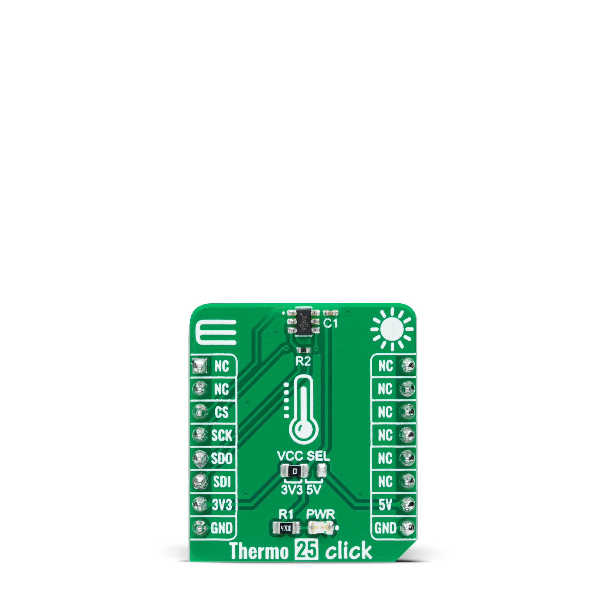
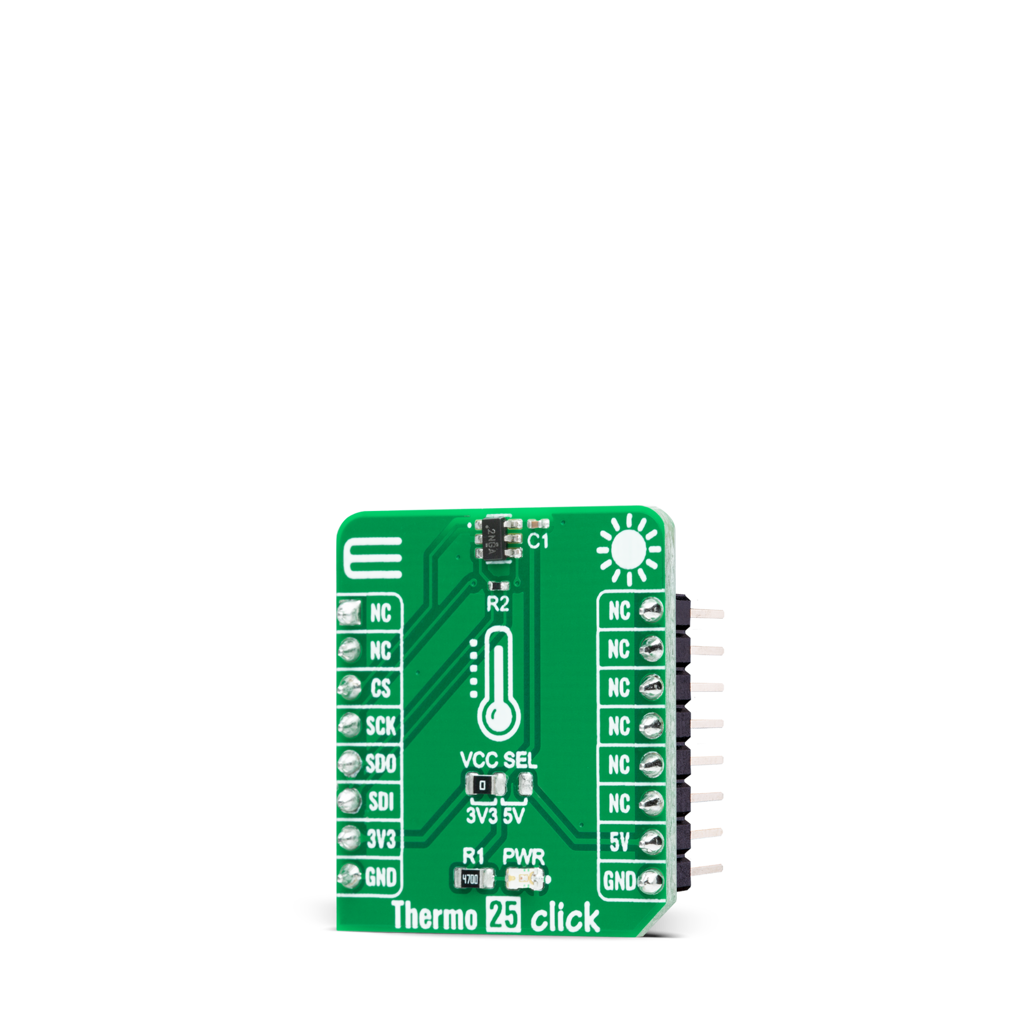
Thermo 25 Click
Dev. board
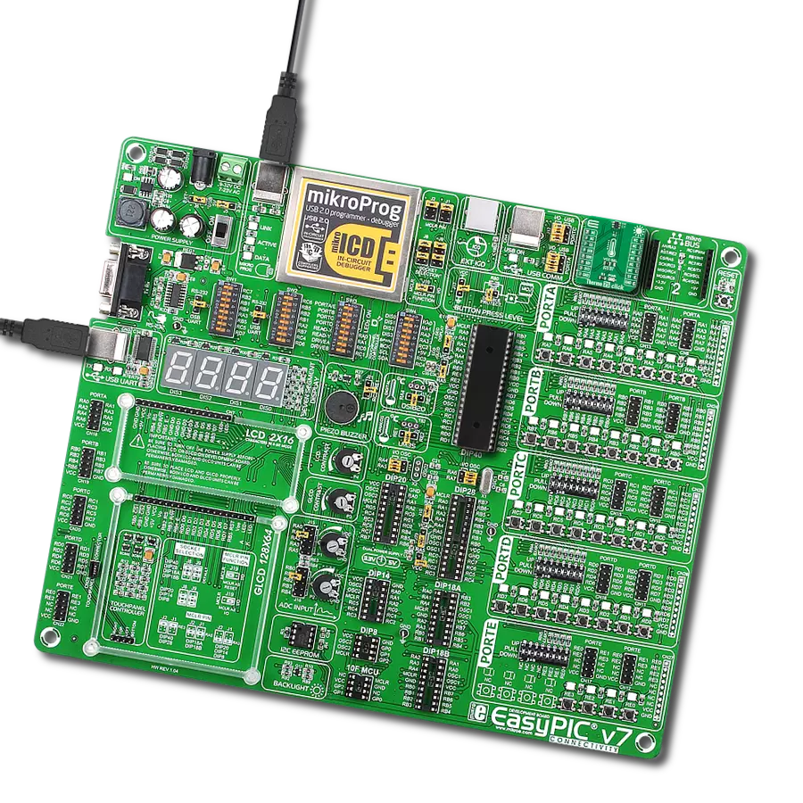
EasyPIC v7
Compiler
NECTO Studio
MCU
PIC18LF45K80
Detects and measures the warmth or coolness of your surroundings
A
A
Hardware Overview
How does it work?
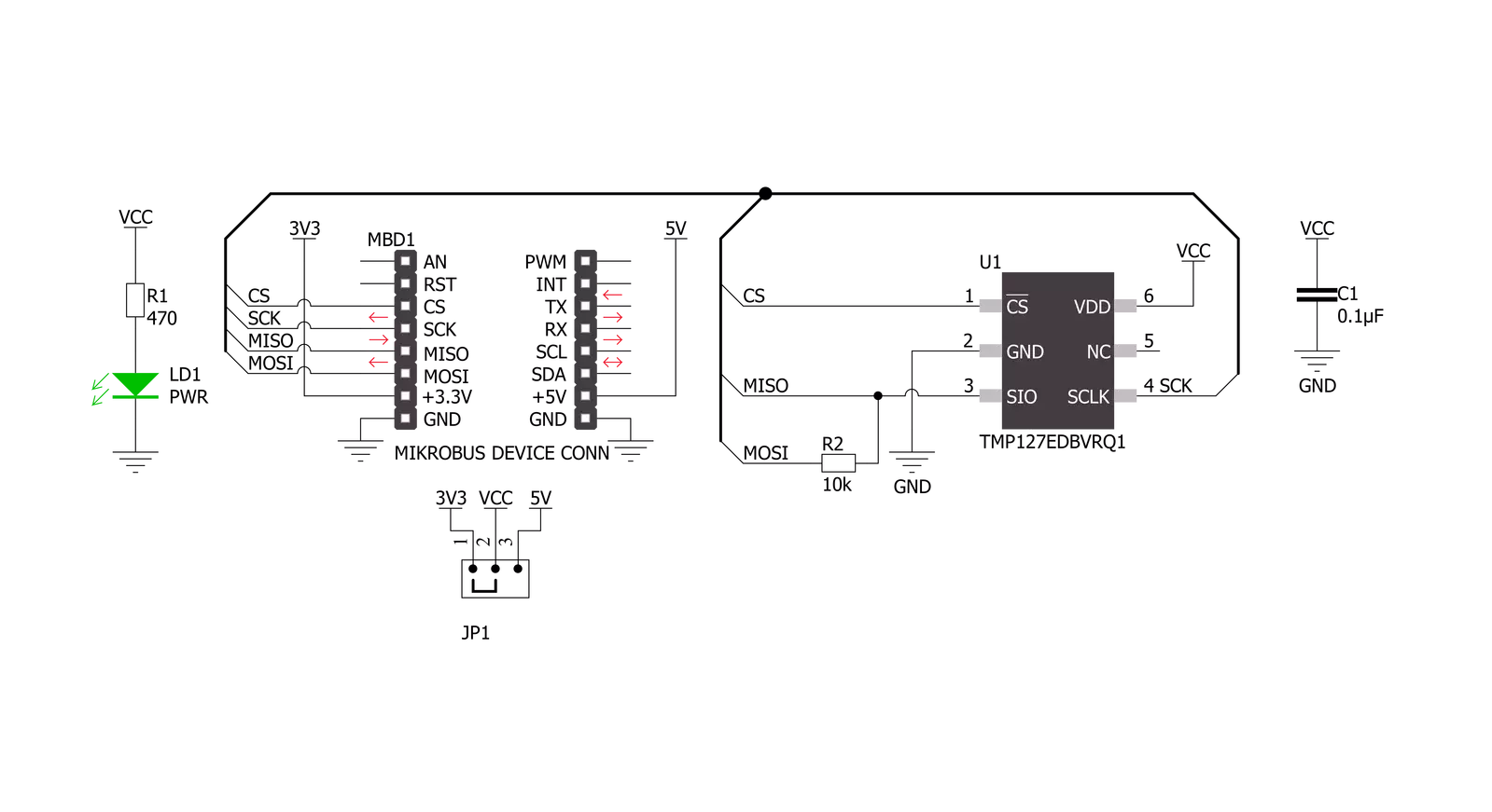
Thermo 25 Click is based on the TMP127-Q1, a factory-calibrated digital output temperature sensor designed for thermal management and thermal protection applications from Texas Instruments. This sensor is characterized by high accuracy and a temperature range of -55°C to +150°C that provides typical ±0.8°C accuracy. It also contains a 14-bit ADC to monitor and digitize the temperature reading to a resolution of 0.03125°C per LSB. The wide supply voltage range, low supply current, and SPI-compatible interface make it ideal for various applications, including process control, environmental monitoring, domestic appliances, and many more. The TMP127-Q1 possesses two operational modes: Continuous-Conversion (CC) and
Shutdown Mode. In the CC mode, ADC performs continuous temperature conversions and stores each result in the temperature register, overwriting the result from the previous conversion. The Shutdown mode reduces power consumption in the TMP127-Q1 when continuous temperature monitoring is not required. The TMP127-Q1 continuously powers up in the Continuous-Conversion mode, while the Shutdown mode can optimize current consumption for low-power applications. This Click board™ communicates with MCU through a standard SPI interface (compatible with SPI or MICROWIRE bus specifications) supporting the two most common SPI modes, SPI Mode 0 and 3,
with a maximum frequency of 10MHz. The SPI interface features a simplified no-register map protocol with a read-write 4-wire configuration. Writing to the TMP127-Q1 will allow the system to use the Shutdown mode and read the device ID. This Click board™ can operate with either 3.3V or 5V logic voltage levels selected via the VCC SEL jumper. This way, both 3.3V and 5V capable MCUs can use the communication lines properly. However, the Click board™ comes equipped with a library containing easy-to-use functions and an example code that can be used, as a reference, for further development.
Features overview
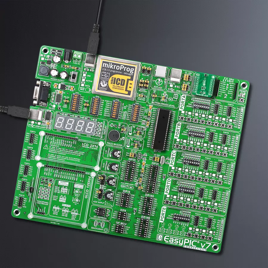
Development board
EasyPIC v7 is the seventh generation of PIC development boards specially designed to develop embedded applications rapidly. It supports a wide range of 8-bit PIC microcontrollers from Microchip and has a broad set of unique functions, such as a powerful onboard mikroProg programmer and In-Circuit debugger over USB-B. The development board is well organized and designed so that the end-user has all the necessary elements in one place, such as switches, buttons, indicators, connectors, and others. With four different connectors for each port, EasyPIC v7 allows you to connect accessory boards, sensors, and custom electronics more efficiently than ever. Each part of
the EasyPIC v7 development board contains the components necessary for the most efficient operation of the same board. An integrated mikroProg, a fast USB 2.0 programmer with mikroICD hardware In-Circuit Debugger, offers many valuable programming/debugging options and seamless integration with the Mikroe software environment. Besides it also includes a clean and regulated power supply block for the development board. It can use various external power sources, including an external 12V power supply, 7-23V AC or 9-32V DC via DC connector/screw terminals, and a power source via the USB Type-B (USB-B) connector. Communication options such as
USB-UART and RS-232 are also included, alongside the well-established mikroBUS™ standard, three display options (7-segment, graphical, and character-based LCD), and several different DIP sockets. These sockets cover a wide range of 8-bit PIC MCUs, from PIC10F, PIC12F, PIC16F, PIC16Enh, PIC18F, PIC18FJ, and PIC18FK families. EasyPIC v7 is an integral part of the Mikroe ecosystem for rapid development. Natively supported by Mikroe software tools, it covers many aspects of prototyping and development thanks to a considerable number of different Click boards™ (over a thousand boards), the number of which is growing every day.

Microcontroller Overview
MCU Card / MCU
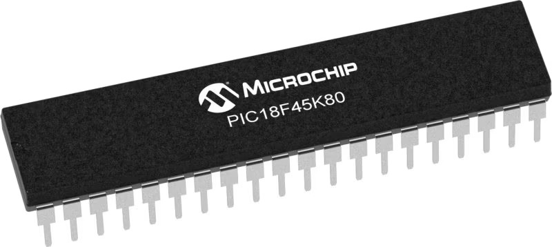
Architecture
PIC
MCU Memory (KB)
32
Silicon Vendor
Microchip
Pin count
40
RAM (Bytes)
3648
Used MCU Pins
mikroBUS™ mapper
Take a closer look
Click board™ Schematic
Step by step
Project assembly

Start by selecting your development board and Click board™. Begin with the EasyPIC v7 as your development board.


Software Support
Library Description
This library contains API for Thermo 25 Click driver.
Key functions:
thermo25_check_communicationThis function sets the operating mode to shutdown, then reads and verifies the device ID and switches back to the continuous mode.thermo25_read_temperatureThis function reads the temperature measurements in degrees Celsius.thermo25_set_modeThis function sets the device operating mode to shutdown or continuous mode by using SPI serial interface.
Open Source
Code example
The complete application code and a ready-to-use project are available through the NECTO Studio Package Manager for direct installation in the NECTO Studio. The application code can also be found on the MIKROE GitHub account.
/*!
 * @file main.c
 * @brief Thermo 25 Click example
 *
 * # Description
 * This example demonstrates the use of Thermo 25 Click board by reading and displaying
 * the temperature measurements.
 *
 * The demo application is composed of two sections :
 *
 * ## Application Init
 * Initializes the driver and logger, and checks the communication by setting the operating mode
 * to shutdown, reading and verifying the device ID, and switching back to the continuous mode.
 *
 * ## Application Task
 * Reads the temperature measurement in degrees Celsius and displays the results on the USB UART
 * approximately once per second.
 *
 * @author Stefan Filipovic
 *
 */

#include "board.h"
#include "log.h"
#include "thermo25.h"

static thermo25_t thermo25;
static log_t logger;

void application_init ( void )
{
    log_cfg_t log_cfg;  /**< Logger config object. */
    thermo25_cfg_t thermo25_cfg;  /**< Click config object. */

    /**
     * Logger initialization.
     * Default baud rate: 115200
     * Default log level: LOG_LEVEL_DEBUG
     * @note If USB_UART_RX and USB_UART_TX
     * are defined as HAL_PIN_NC, you will
     * need to define them manually for log to work.
     * See @b LOG_MAP_USB_UART macro definition for detailed explanation.
     */
    LOG_MAP_USB_UART( log_cfg );
    log_init( &logger, &log_cfg );
    log_info( &logger, " Application Init " );

    // Click initialization.
    thermo25_cfg_setup( &thermo25_cfg );
    THERMO25_MAP_MIKROBUS( thermo25_cfg, MIKROBUS_1 );
    if ( SPI_MASTER_ERROR == thermo25_init( &thermo25, &thermo25_cfg ) )
    {
        log_error( &logger, " Communication init." );
        for ( ; ; );
    }

    if ( THERMO25_ERROR == thermo25_check_communication ( &thermo25 ) )
    {
        log_error( &logger, " Check communication." );
        for ( ; ; );
    }

    log_info( &logger, " Application Task " );
}

void application_task ( void )
{
    float temperature;
    if ( THERMO25_OK == thermo25_read_temperature ( &thermo25, &temperature ) )
    {
        log_printf ( &logger, " Temperature: %.2f degC\r\n\n", temperature );
        Delay_ms ( 1000 );
    }
}

int main ( void )
{
    /* Do not remove this line or clock might not be set correctly. */
    #ifdef PREINIT_SUPPORTED
    preinit();
    #endif

    application_init( );

    for ( ; ; )
    {
        application_task( );
    }

    return 0;
}

// ------------------------------------------------------------------------ END
Additional Support
Resources
Category:Temperature & humidity


