Experience the power of touch with CAP1114 and PIC32MZ2048EFH100
Say goodbye to clunky buttons and switches
Published Apr 24, 2023
Click board™
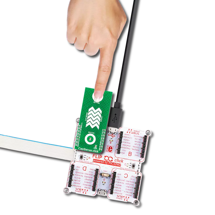
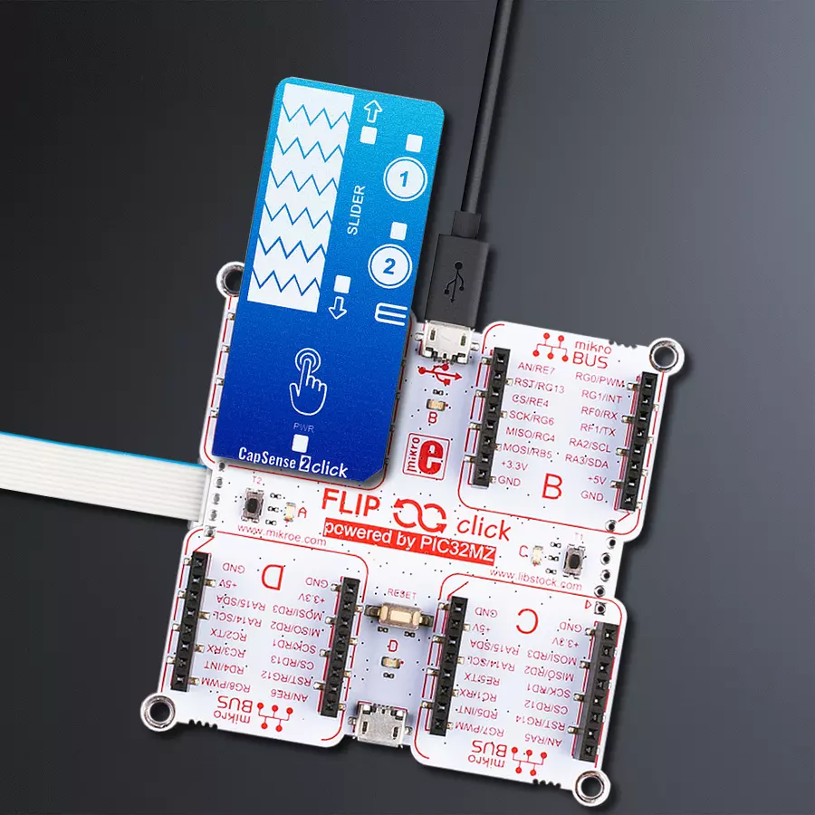
CapSense 2 Click
Dev. board
Flip&Click PIC32MZ
Compiler
NECTO Studio
MCU
PIC32MZ2048EFH100
Take control of your touch-sensing applications with a slide switch and touch buttons that offers high sensitivity and responsiveness
A
A
Hardware Overview
How does it work?
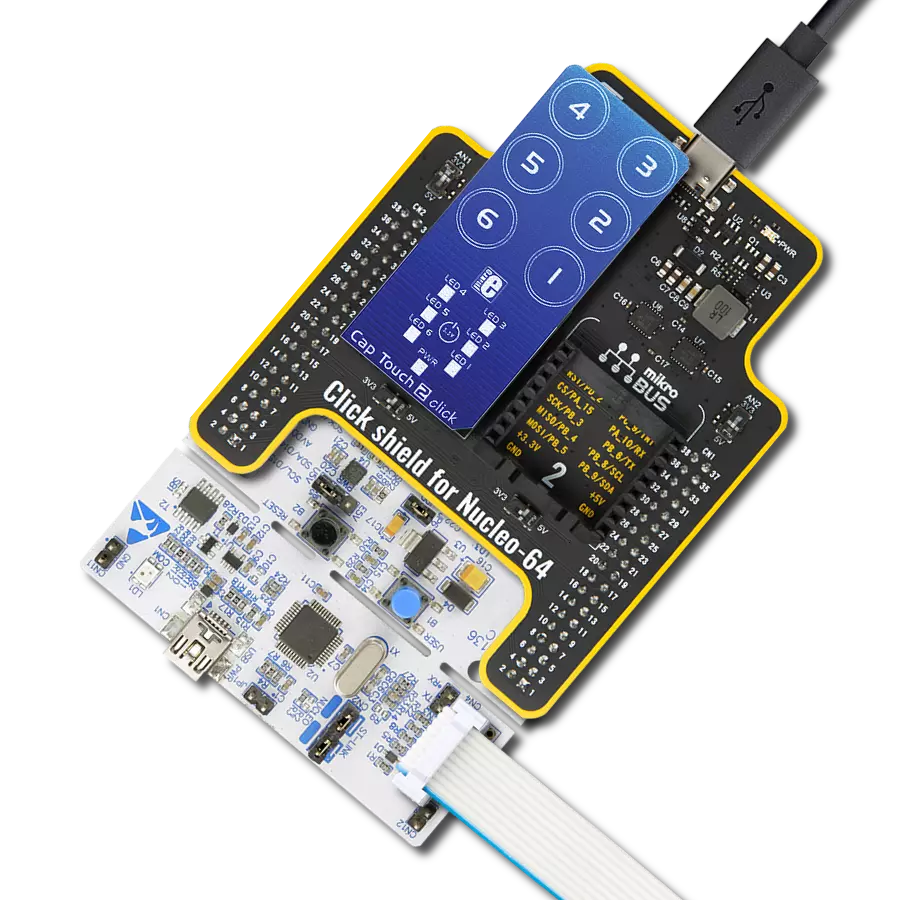
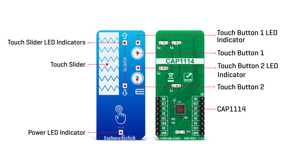
CapSense 2 Click is based on the CAP1114, a multi-channel capacitive touch sensor from Microchip. The CAP1114 takes human body capacitance as an input and directly provides real-time sensor information via a serial interface. It also comes with programmable sensitivity for touch buttons and slider switch applications. The CAP1114 contains multiple power states, including several low-power operating states. It has four operational states: Fully Active, Sleep, Deep Sleep, and Inactive depending on the status of the SLEEP, DEACT, and DSLEEP register bits. When the device transitions between power states, previously detected touches (for deactivated channels) are cleared, and the status bits reset.
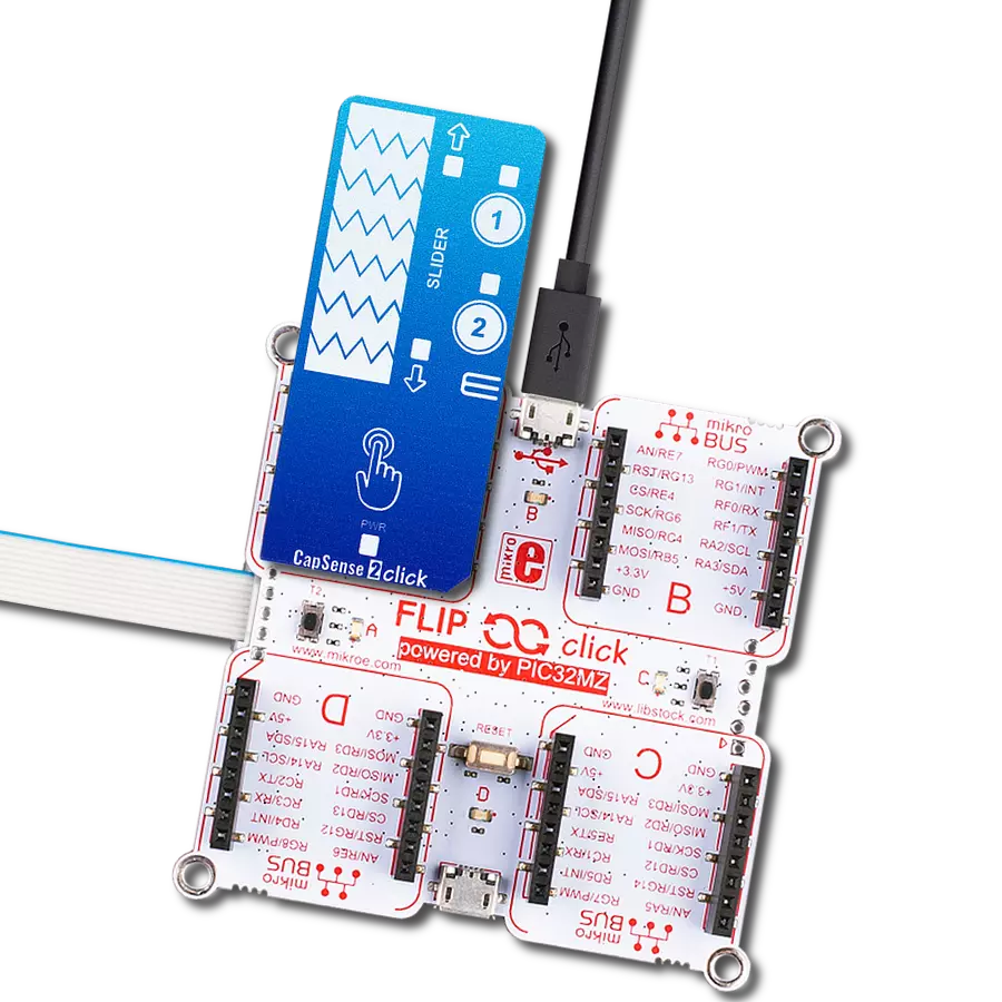
As mentioned earlier, this board contains a 7-segment capacitive sensing slider that can detect a slide in either the UP or DOWN direction, as well as two touch buttons. These pads are the only elements on the top side of the board, allowing the protective acrylic plexiglass layer placement. Each feature has an LED indicator representing the activity in that field. If a touch event is detected on one of these onboard pads, the state of the corresponding LED will be changed, indicating an activated channel; more precisely, touch has been detected on that specific field. CapSense 2 Click communicates with MCU using the standard I2C 2-Wire interface to read data and configure settings. It also possesses an additional alert interrupt signal,
routed on the INT pin of the mikroBUS™ socket labeled as ALT, indicating when a specific interrupt event occurs (touch detection), and the Reset pin routed to the RST pin of the mikroBUS™ socket used to hold all internal blocks of the CAP1114 in a reset state. This Click board™ can only be operated with a 3.3V logic voltage level. The board must perform appropriate logic voltage level conversion before using MCUs with different logic levels. However, the Click board™ comes equipped with a library containing functions and an example code that can be used as a reference for further development.
Features overview
Development board
Flip&Click PIC32MZ is a compact development board designed as a complete solution that brings the flexibility of add-on Click boards™ to your favorite microcontroller, making it a perfect starter kit for implementing your ideas. It comes with an onboard 32-bit PIC32MZ microcontroller, the PIC32MZ2048EFH100 from Microchip, four mikroBUS™ sockets for Click board™ connectivity, two USB connectors, LED indicators, buttons, debugger/programmer connectors, and two headers compatible with Arduino-UNO pinout. Thanks to innovative manufacturing technology,
it allows you to build gadgets with unique functionalities and features quickly. Each part of the Flip&Click PIC32MZ development kit contains the components necessary for the most efficient operation of the same board. In addition, there is the possibility of choosing the Flip&Click PIC32MZ programming method, using the chipKIT bootloader (Arduino-style development environment) or our USB HID bootloader using mikroC, mikroBasic, and mikroPascal for PIC32. This kit includes a clean and regulated power supply block through the USB Type-C (USB-C) connector. All communication
methods that mikroBUS™ itself supports are on this board, including the well-established mikroBUS™ socket, user-configurable buttons, and LED indicators. Flip&Click PIC32MZ development kit allows you to create a new application in minutes. Natively supported by Mikroe software tools, it covers many aspects of prototyping thanks to a considerable number of different Click boards™ (over a thousand boards), the number of which is growing every day.

Microcontroller Overview
MCU Card / MCU

Architecture
PIC32
MCU Memory (KB)
2048
Silicon Vendor
Microchip
Pin count
100
RAM (Bytes)
524288
Used MCU Pins
mikroBUS™ mapper
Take a closer look
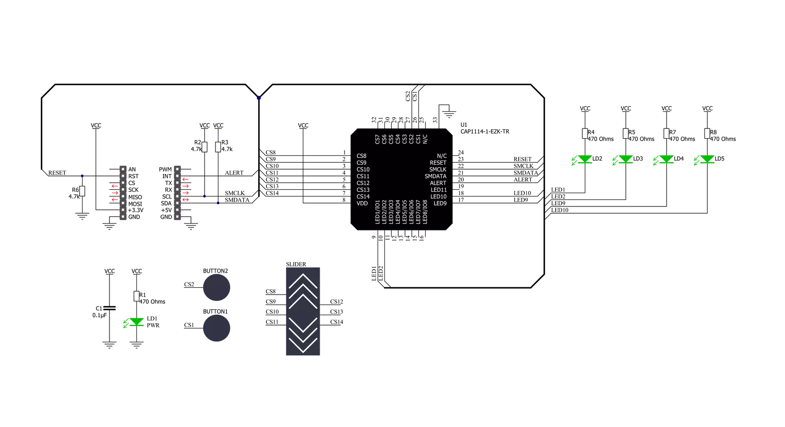
Click board™ Schematic
Step by step
Project assembly

Start by selecting your development board and Click board™. Begin with the Flip&Click PIC32MZ as your development board.


Track your results in real time
Application Output
1. Application Output - In Debug mode, the 'Application Output' window enables real-time data monitoring, offering direct insight into execution results. Ensure proper data display by configuring the environment correctly using the provided tutorial.

2. UART Terminal - Use the UART Terminal to monitor data transmission via a USB to UART converter, allowing direct communication between the Click board™ and your development system. Configure the baud rate and other serial settings according to your project's requirements to ensure proper functionality. For step-by-step setup instructions, refer to the provided tutorial.

3. Plot Output - The Plot feature offers a powerful way to visualize real-time sensor data, enabling trend analysis, debugging, and comparison of multiple data points. To set it up correctly, follow the provided tutorial, which includes a step-by-step example of using the Plot feature to display Click board™ readings. To use the Plot feature in your code, use the function: plot(*insert_graph_name*, variable_name);. This is a general format, and it is up to the user to replace 'insert_graph_name' with the actual graph name and 'variable_name' with the parameter to be displayed.

Software Support
Library Description
This library contains API for CapSense 2 Click driver.
Key functions:
capsense2_read_registerThis function reads a data byte from the selected register by using I2C serial interface.capsense2_get_alert_pinThis function returns the alert pin logic state.capsense2_clear_interruptThis function clears the INT bit of the main status register if the interrupt pin is asserted.
Open Source
Code example
The complete application code and a ready-to-use project are available through the NECTO Studio Package Manager for direct installation in the NECTO Studio. The application code can also be found on the MIKROE GitHub account.
/*!
 * @file main.c
 * @brief CapSense2 Click example
 *
 * # Description
 * This example demonstrates the use of CapSense 2 Click board by reading
 * and displaying the sensor's events.
 *
 * The demo application is composed of two sections :
 *
 * ## Application Init
 * Initializes the driver and performs the Click default configuration
 * which resets the Click board and links the desired LEDs to buttons and swipe sensors.
 *
 * ## Application Task
 * Waits for an event interrupt and displays the event on the USB UART.
 *
 * @author Stefan Filipovic
 *
 */

#include "board.h"
#include "log.h"
#include "capsense2.h"

static capsense2_t capsense2;
static log_t logger;

void application_init ( void )
{
    log_cfg_t log_cfg;  /**< Logger config object. */
    capsense2_cfg_t capsense2_cfg;  /**< Click config object. */

    /**
     * Logger initialization.
     * Default baud rate: 115200
     * Default log level: LOG_LEVEL_DEBUG
     * @note If USB_UART_RX and USB_UART_TX
     * are defined as HAL_PIN_NC, you will
     * need to define them manually for log to work.
     * See @b LOG_MAP_USB_UART macro definition for detailed explanation.
     */
    LOG_MAP_USB_UART( log_cfg );
    log_init( &logger, &log_cfg );
    log_info( &logger, " Application Init " );

    // Click initialization.
    capsense2_cfg_setup( &capsense2_cfg );
    CAPSENSE2_MAP_MIKROBUS( capsense2_cfg, MIKROBUS_1 );
    if ( I2C_MASTER_ERROR == capsense2_init( &capsense2, &capsense2_cfg ) )
    {
        log_error( &logger, " Communication init." );
        for ( ; ; );
    }

    if ( CAPSENSE2_ERROR == capsense2_default_cfg ( &capsense2 ) )
    {
        log_error( &logger, " Default configuration." );
        for ( ; ; );
    }

    log_info( &logger, " Application Task " );
}

void application_task ( void )
{
    if ( capsense2_get_alert_pin ( &capsense2 ) )
    {
        uint8_t button_status = 0;
        if ( CAPSENSE2_OK == capsense2_read_register ( &capsense2, CAPSENSE2_REG_BUTTON_STATUS_1, &button_status ) )
        {
            static uint8_t button_press_state = 0;
            static uint8_t swipe_state = 0;
            if ( button_status & CAPSENSE2_BUTTON_STATUS_1_UP_SLIDER )
            {
                if ( CAPSENSE2_BUTTON_STATUS_1_UP_SLIDER != swipe_state )
                {
                    log_printf ( &logger, " Swipe UP \r\n\n" );
                    swipe_state = CAPSENSE2_BUTTON_STATUS_1_UP_SLIDER;
                }
            }
            if ( button_status & CAPSENSE2_BUTTON_STATUS_1_DOWN_SLIDER )
            {
                if ( CAPSENSE2_BUTTON_STATUS_1_DOWN_SLIDER != swipe_state )
                {
                    log_printf ( &logger, " Swipe DOWN \r\n\n" );
                    swipe_state = CAPSENSE2_BUTTON_STATUS_1_DOWN_SLIDER;
                }
            }
            if ( button_status & CAPSENSE2_BUTTON_STATUS_1_BUTTON_1 )
            {
                if ( !( button_press_state & CAPSENSE2_BUTTON_STATUS_1_BUTTON_1 ) )
                {
                    log_printf ( &logger, " Button 1 pressed \r\n\n" );
                    button_press_state |= CAPSENSE2_BUTTON_STATUS_1_BUTTON_1;
                }
            }
            if ( button_status & CAPSENSE2_BUTTON_STATUS_1_BUTTON_2 )
            {
                if ( !( button_press_state & CAPSENSE2_BUTTON_STATUS_1_BUTTON_2 ) )
                {
                    log_printf ( &logger, " Button 2 pressed \r\n\n" );
                    button_press_state |= CAPSENSE2_BUTTON_STATUS_1_BUTTON_2;
                }
            }
            capsense2_clear_interrupt ( &capsense2 );

            // check if buttons are released
            if ( CAPSENSE2_OK == capsense2_read_register ( &capsense2, CAPSENSE2_REG_BUTTON_STATUS_1, &button_status ) )
            {
                if ( ( button_press_state & CAPSENSE2_BUTTON_STATUS_1_BUTTON_1 ) &&
                    !( button_status & CAPSENSE2_BUTTON_STATUS_1_BUTTON_1 ) )
                {
                    log_printf ( &logger, " Button 1 released \r\n\n" );
                    button_press_state &= ~CAPSENSE2_BUTTON_STATUS_1_BUTTON_1;
                }
                if ( ( button_press_state & CAPSENSE2_BUTTON_STATUS_1_BUTTON_2 ) &&
                    !( button_status & CAPSENSE2_BUTTON_STATUS_1_BUTTON_2 ) )
                {
                    log_printf ( &logger, " Button 2 released \r\n\n" );
                    button_press_state &= ~CAPSENSE2_BUTTON_STATUS_1_BUTTON_2;
                }
            }

            // check if swipe event is finished and display the slider position
            uint8_t slider = 0;
            if ( CAPSENSE2_OK == capsense2_read_register ( &capsense2, CAPSENSE2_REG_SLIDER_POSITION_DATA, &slider ) )
            {
                if ( slider )
                {
                    log_printf ( &logger, " Slider position: %u \r\n\n", ( uint16_t ) slider );
                }
                else
                {
                    swipe_state = 0;
                }
            }
        }
        capsense2_clear_interrupt ( &capsense2 );
    }
}

int main ( void )
{
    /* Do not remove this line or clock might not be set correctly. */
    #ifdef PREINIT_SUPPORTED
    preinit();
    #endif

    application_init( );

    for ( ; ; )
    {
        application_task( );
    }

    return 0;
}

// ------------------------------------------------------------------------ END
Additional Support
Resources
Category:Capacitive