Take your senses to the next level with DA7282 and PIC32MZ2048EFH100
Experience haptic feedback like never before!

Published Apr 03, 2023
Click board™
Haptic 3 Click
Dev. board
Flip&Click PIC32MZ
Compiler
NECTO Studio
MCU
PIC32MZ2048EFH100
The haptic driver that brings your digital world to life with realistic touch feedback!
A
A
Hardware Overview
How does it work?
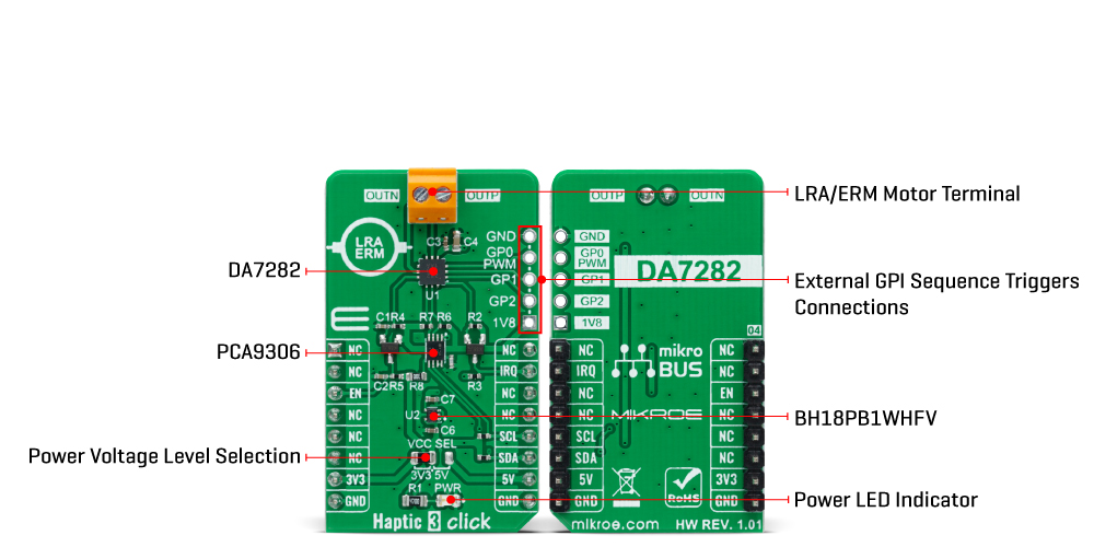
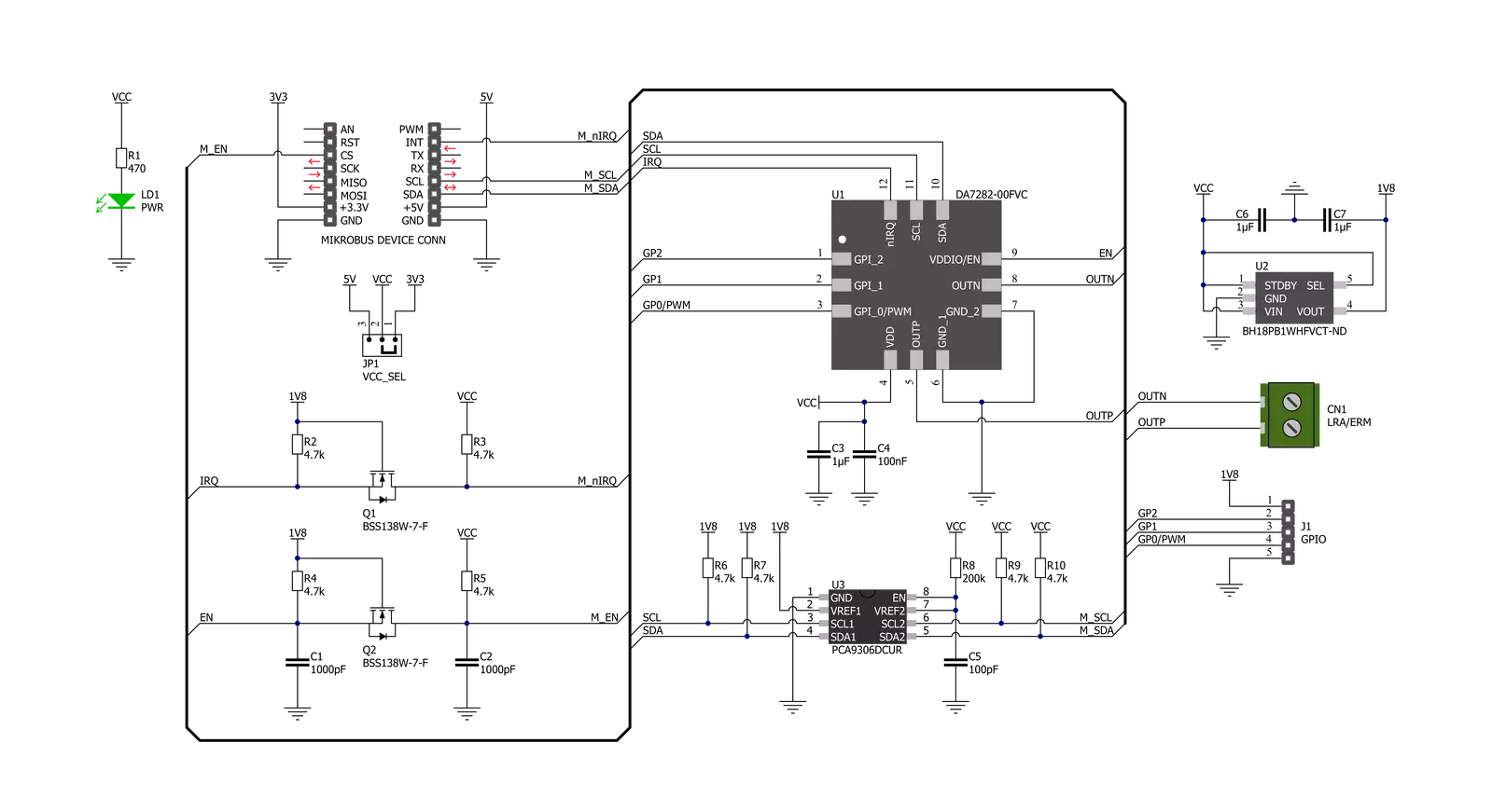
Haptic 3 Click is based on the DA7282, a haptic driver capable of driving both LRA and ERM actuators from Dialog Semiconductor. The power-optimized architecture and advanced closed-loop digital algorithms achieve a high-fidelity haptic drive. The DA7282 features frequency control within an onboard Waveform Memory and three distinct general-purpose inputs for triggering up to six specific sequences, which helps with emulating button pressing in many applications. The device controls drive levels based on the sequence selected by the I2C interface across the load and senses the movement of the actuator. The driven waveform is generated by a current-regulated loop using a high-frequency PWM modulation. The differential output drive features a switching regulator architecture with an H-bridge differential drive across the load at 187.5kHz. The DA7282 can also perform close-loop actuator monitoring while driving to enable calibration-free playback, frequency tracking
(LRA only), Active Acceleration, Rapid Stop, and actuator diagnostics. Resonant frequency tracking can be enabled while driving an LRA to track the mechanical resonance of the actuator through closed-loop control or can be disabled to operate DA7282 in open-loop wideband frequency operation while driving LRAs with a broader bandwidth frequency response. Also, Active Acceleration and Rapid Stop features enable automated driving of both ERM and LRA loads (when frequency tracking is enabled), which reduces the time to reach the target acceleration level and the time for the actuator to come to a complete stop. Although it can use both mikroBUS™ power rails for regular power supply, its digital part requires a voltage level of 1.8V to work correctly. Therefore, a small regulating LDO, the BH18PB1WHFV, provides a 1.8V out of 5V and 3.3V mikroBUS™ power rails alongside Enable feature through the EN pin of the mikroBUS™ socket, offering a switch operation to turn ON/OFF
power delivery to the connected load. Haptic 3 Click communicates with MCU using the standard I2C 2-Wire interface with a maximum clock frequency of 400kHz. Since the sensor for communication requires a logic level of 1.8V, this Click board™ also features the PCA9306 voltage-level translator. The I2C interface bus lines are routed to the voltage-level translators allowing this Click board™ to work with both 3.3V and 5V MCUs properly. Also, it uses an interrupt pin, routed to the IRQ pin of the mikroBUS™ socket, when a different fault condition occurs to alert the MCU. This Click board™ can operate with either 3.3V or 5V logic voltage levels selected via the VCC SEL jumper. This way, both 3.3V and 5V capable MCUs can use the communication lines properly. However, the Click board™ comes equipped with a library containing easy-to-use functions and an example code that can be used, as a reference, for further development.
Features overview
Development board
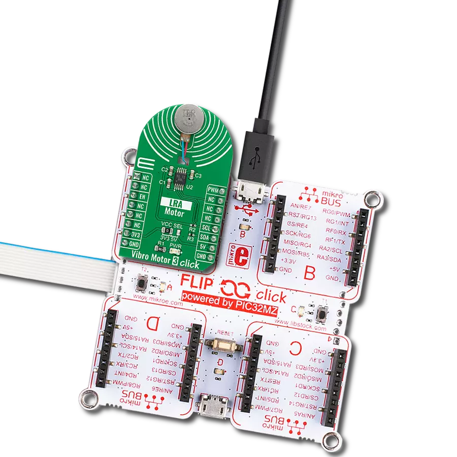
Flip&Click PIC32MZ is a compact development board designed as a complete solution that brings the flexibility of add-on Click boards™ to your favorite microcontroller, making it a perfect starter kit for implementing your ideas. It comes with an onboard 32-bit PIC32MZ microcontroller, the PIC32MZ2048EFH100 from Microchip, four mikroBUS™ sockets for Click board™ connectivity, two USB connectors, LED indicators, buttons, debugger/programmer connectors, and two headers compatible with Arduino-UNO pinout. Thanks to innovative manufacturing technology,
it allows you to build gadgets with unique functionalities and features quickly. Each part of the Flip&Click PIC32MZ development kit contains the components necessary for the most efficient operation of the same board. In addition, there is the possibility of choosing the Flip&Click PIC32MZ programming method, using the chipKIT bootloader (Arduino-style development environment) or our USB HID bootloader using mikroC, mikroBasic, and mikroPascal for PIC32. This kit includes a clean and regulated power supply block through the USB Type-C (USB-C) connector. All communication
methods that mikroBUS™ itself supports are on this board, including the well-established mikroBUS™ socket, user-configurable buttons, and LED indicators. Flip&Click PIC32MZ development kit allows you to create a new application in minutes. Natively supported by Mikroe software tools, it covers many aspects of prototyping thanks to a considerable number of different Click boards™ (over a thousand boards), the number of which is growing every day.

Microcontroller Overview
MCU Card / MCU

Architecture
PIC32
MCU Memory (KB)
2048
Silicon Vendor
Microchip
Pin count
100
RAM (Bytes)
524288
You complete me!
Accessories
Vibration ERM Motor 9K RPM 3V (VC1026B002F - old MPN C1026B002F) represents a compact-size Eccentric Rotating Mass (ERM) motor designed by Vybronics. This type of motor contains a small eccentric weight on its rotor, so while rotating, it also produces a vibration effect often used for haptic feedback on many small handheld devices. Due to its circular shape with a diameter of 10mm, the VC1026B002F is often referred to as a coin motor. The main characteristics of this vibration motor are its supply voltage, in this case, 3VDC, maximum rated current of 85mA, and the rated speed of 9000RPM, which produces the highest G force/vibration energy of 0.80GRMS. It can also be used with self-adhesive tape to mount it on your PCB or the inner wall of your product's housing.

Used MCU Pins
mikroBUS™ mapper
Take a closer look
Click board™ Schematic
Step by step
Project assembly

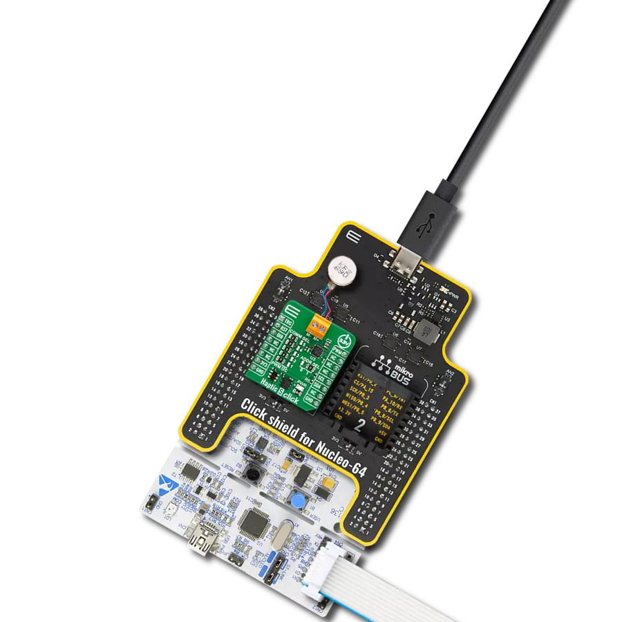
Start by selecting your development board and Click board™. Begin with the Flip&Click PIC32MZ as your development board.


Track your results in real time
Application Output
1. Application Output - In Debug mode, the 'Application Output' window enables real-time data monitoring, offering direct insight into execution results. Ensure proper data display by configuring the environment correctly using the provided tutorial.

2. UART Terminal - Use the UART Terminal to monitor data transmission via a USB to UART converter, allowing direct communication between the Click board™ and your development system. Configure the baud rate and other serial settings according to your project's requirements to ensure proper functionality. For step-by-step setup instructions, refer to the provided tutorial.

3. Plot Output - The Plot feature offers a powerful way to visualize real-time sensor data, enabling trend analysis, debugging, and comparison of multiple data points. To set it up correctly, follow the provided tutorial, which includes a step-by-step example of using the Plot feature to display Click board™ readings. To use the Plot feature in your code, use the function: plot(*insert_graph_name*, variable_name);. This is a general format, and it is up to the user to replace 'insert_graph_name' with the actual graph name and 'variable_name' with the parameter to be displayed.

Software Support
Library Description
This library contains API for Haptic 3 Click driver.
Key functions:
haptic3_set_vibration_levelThis function sets the motor vibration level.haptic3_get_vibration_levelThis function reads the motor vibration level.haptic3_write_registerThis function writes desired data to the selected register by using I2C serial interface.
Open Source
Code example
The complete application code and a ready-to-use project are available through the NECTO Studio Package Manager for direct installation in the NECTO Studio. The application code can also be found on the MIKROE GitHub account.
/*!
 * @file main.c
 * @brief HAPTIC3 Click example
 *
 * # Description
 * This example demonstrates the use of HAPTIC 3 Click board by controlling
 * the attached motor vibration level.
 *
 * The demo application is composed of two sections :
 *
 * ## Application Init
 * Initializes the driver and performs the Click default configuration.
 *
 * ## Application Task
 * Changes the motor vibration level every 2 seconds from MAX to MIN,
 * and displays the currently set level on the USB UART.
 *
 * @author Stefan Filipovic
 *
 */

#include "board.h"
#include "log.h"
#include "haptic3.h"

static haptic3_t haptic3;
static log_t logger;

void application_init ( void )
{
    log_cfg_t log_cfg;  /**< Logger config object. */
    haptic3_cfg_t haptic3_cfg;  /**< Click config object. */

    /**
     * Logger initialization.
     * Default baud rate: 115200
     * Default log level: LOG_LEVEL_DEBUG
     * @note If USB_UART_RX and USB_UART_TX
     * are defined as HAL_PIN_NC, you will
     * need to define them manually for log to work.
     * See @b LOG_MAP_USB_UART macro definition for detailed explanation.
     */
    LOG_MAP_USB_UART( log_cfg );
    log_init( &logger, &log_cfg );
    log_info( &logger, " Application Init " );

    // Click initialization.
    haptic3_cfg_setup( &haptic3_cfg );
    HAPTIC3_MAP_MIKROBUS( haptic3_cfg, MIKROBUS_1 );
    if ( I2C_MASTER_ERROR == haptic3_init( &haptic3, &haptic3_cfg ) )
    {
        log_error( &logger, " Communication init." );
        for ( ; ; );
    }

    if ( HAPTIC3_ERROR == haptic3_default_cfg ( &haptic3 ) )
    {
        log_error( &logger, " Default configuration." );
        for ( ; ; );
    }

    log_info( &logger, " Application Task " );
}

void application_task ( void )
{
    float vibration_level;
    if ( HAPTIC3_OK == haptic3_set_vibration_level ( &haptic3, HAPTIC3_VIBRATION_LEVEL_MAX ) )
    {
        if ( HAPTIC3_OK == haptic3_get_vibration_level ( &haptic3, &vibration_level ) )
        {
            log_printf( &logger, " Vibration level: %.3f \r\n\n", vibration_level );
        }
    }
    Delay_ms ( 1000 );
    Delay_ms ( 1000 );

    if ( HAPTIC3_OK == haptic3_set_vibration_level ( &haptic3, HAPTIC3_VIBRATION_LEVEL_MIN ) )
    {
        if ( HAPTIC3_OK == haptic3_get_vibration_level ( &haptic3, &vibration_level ) )
        {
            log_printf( &logger, " Vibration level: %.3f \r\n\n", vibration_level );
        }
    }
    Delay_ms ( 1000 );
    Delay_ms ( 1000 );
}

int main ( void )
{
    /* Do not remove this line or clock might not be set correctly. */
    #ifdef PREINIT_SUPPORTED
    preinit();
    #endif

    application_init( );

    for ( ; ; )
    {
        application_task( );
    }

    return 0;
}

// ------------------------------------------------------------------------ END
Additional Support
Resources
Category:Haptic