Enable RFID-based identification and tracking with Pepper C1 (000600) and STM32F302VC
Advanced RFID, Wi-Fi, and WPAN connectivity solution for smart embedded applications
Published Jul 22, 2025
Click board™
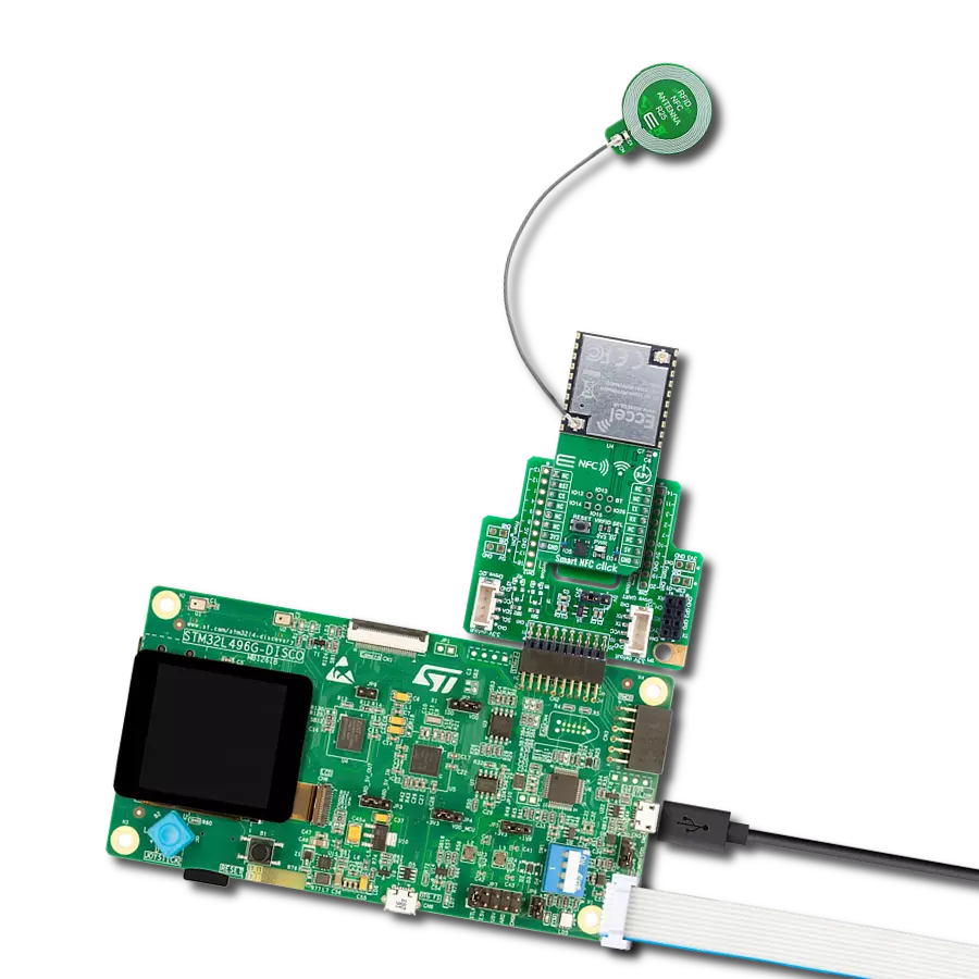
Smart NFC Click
Dev. board
CLICKER 4 for STM32F302VCT6
Compiler
NECTO Studio
MCU
STM32F302VC
Integrate advanced RFID, Wi-Fi, and WPAN capabilities with OTA updates perfect for contactless service systems
A
A
Hardware Overview
How does it work?
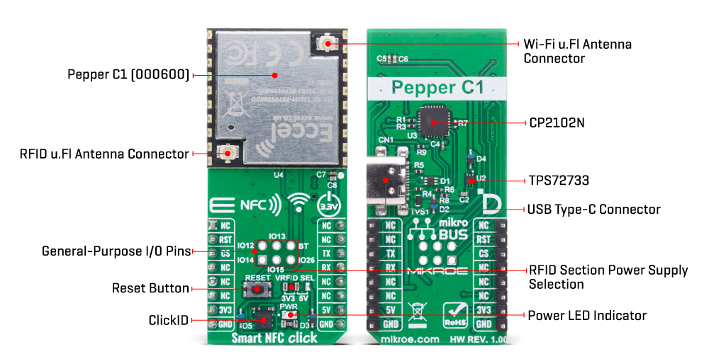
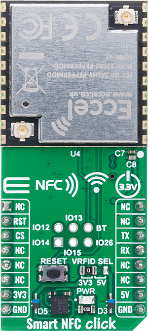
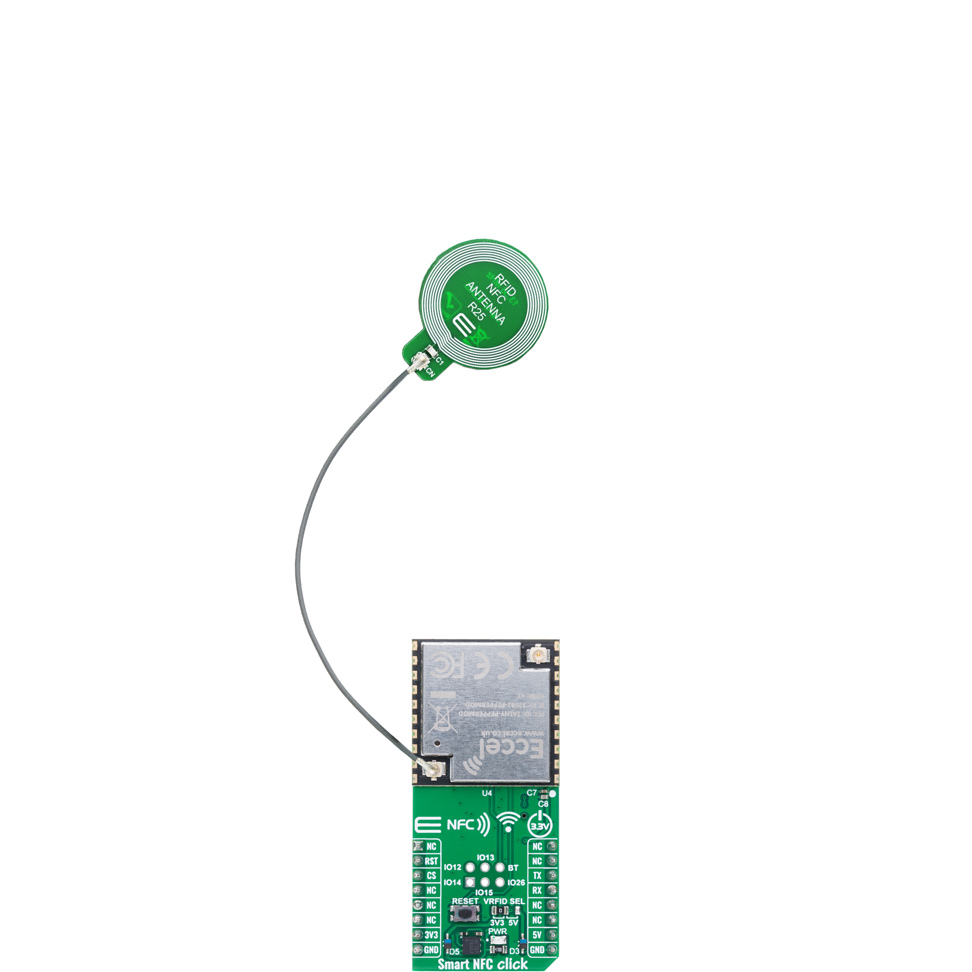
Smart NFC Click is based on the Pepper C1 (000600) module from Eccel Technology that supports both Wi-Fi 802.11 b/g/n and 2.4GHz WPAN connectivity, which can be disabled if needed, offering flexibility in various deployment scenarios. Thanks to its built-in wireless capabilities, the module allows for free lifetime Over-the-Air (OTA) firmware updates, and supports communication over TCP in addition to the traditional UART interface, making it suitable for modern connected systems. The Pepper C1 (000600) module also supports numerous RFID tag technologies, including MIFARE® Classic® 1K and 4K, MIFARE Ultralight®, MIFARE DESFire® EV1/EV2, MIFARE Plus®, and ICODE, giving users the freedom to implement a variety of contactless systems without deep RFID or embedded software knowledge. What sets Smart NFC Click apart is its ability to operate in standalone mode, enabling integration into IoT ecosystems without the need for additional processing or control. It supports a wide range of popular IoT communication protocols such as MQTT, REST API, and TCP sockets, allowing developers to build secure and efficient RFID-enabled solutions. At the heart of the Pepper C1 (000600) module is a powerful 32-bit microcontroller that manages RFID operations and simplifies configuration through a robust command
interface, providing fast and straightforward read/write access to supported transponders. Thanks to all features, the Smart NFC Click is an excellent choice for a range of applications such as access control, goods tracking, consumables monitoring, pre-paid systems, resource management, contactless data storage, and the development and evaluation of RFID solutions. Smart NFC Click communicates with the host MCU through a UART interface using the standard UART RX and TX pins. The default communication speed is set at 115200bps, ensuring efficient data exchange. Along with the communication and control pins, this Click board™ also includes a reset pin (RST) and a RESET button, enabling easy module resetting. This board also includes a USB Type-C connector for USB 2.0 Full Speed capability, allowing for configuration via a PC. This functionality is enabled by the CP2102N, a USB-to-UART bridge. The board also includes an unsoldered header featuring six user-configurable GPIO pins, offering additional flexibility for integration with external peripherals or custom functions. Among these pins, one is specifically designated as the BT pin, intended for use as a Button input, enabling interactive control or triggering of specific module actions based on user input. The module features two onboard u.FL
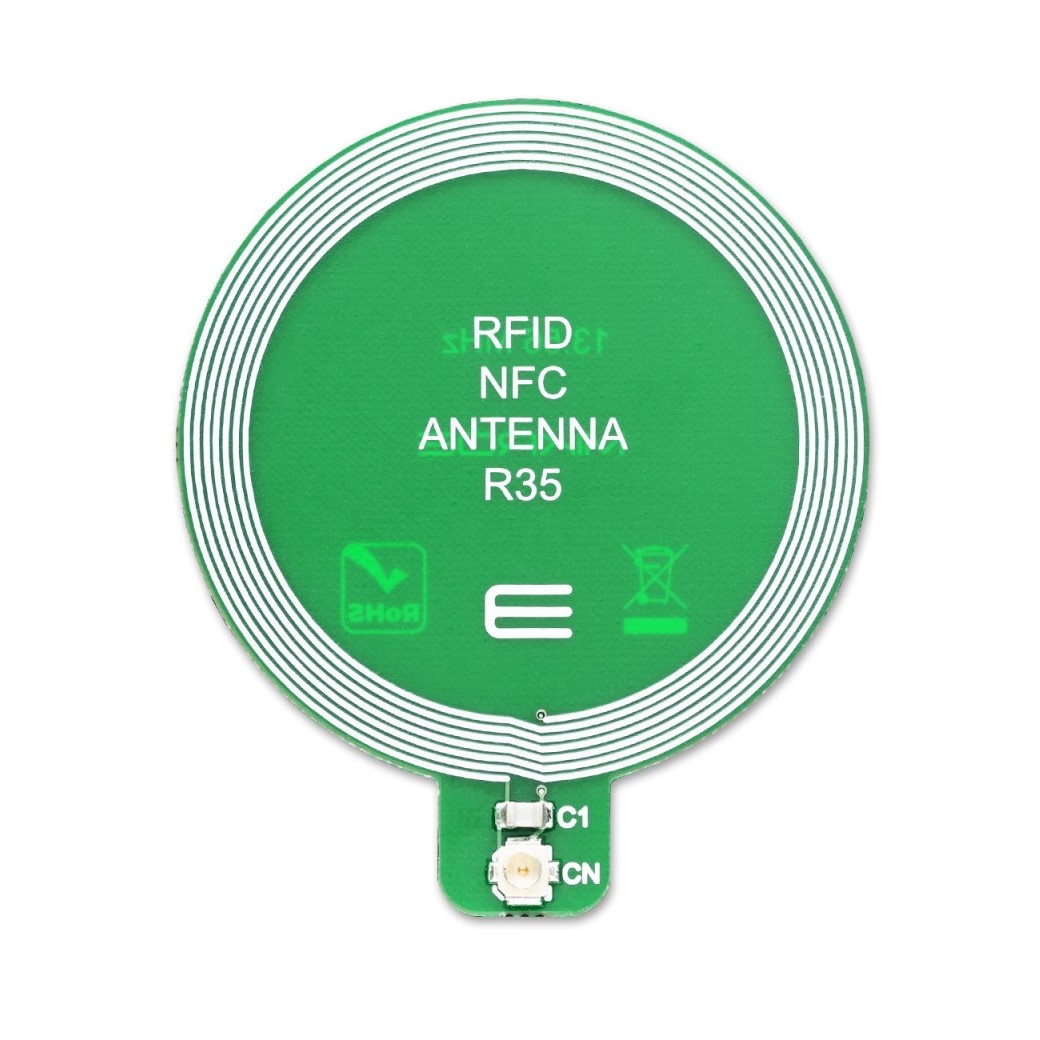
connectors, one dedicated to the Wi-Fi antenna and the other to the RFID antenna, ensuring optimal wireless performance in both communication domains. For RFID applications, users can take advantage of MIKROE’s own Circular NFC R25 Antenna, which is fully compatible with the module, along with 13.56MHz RFID tags that adhere to the ISO14443-A standard, also available from the MIKROE product range. This combination allows for reliable and efficient contactless communication in various embedded and IoT applications. Smart NFC Click supports both 3.3V and 5V power rails, ensuring compatibility with a wide range of development systems. However, the module itself is primarily powered by the 3.3V rail, which serves as the main supply for its core operation. For the RFID section specifically, the board includes a VRFID SEL jumper that allows the user to select between 3.3V and 5V as the power supply, providing additional flexibility when working with different types of RFID transponders or adapting to system-level voltage requirements. Also, this Click board™ comes equipped with a library containing easy-to-use functions and an example code that can be used as a reference for further development.
Features overview
Development board
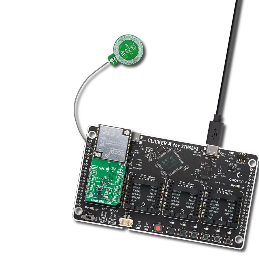
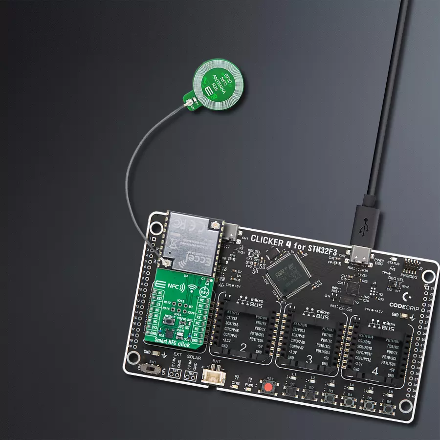
Clicker 4 for STM32F3 is a compact development board designed as a complete solution, you can use it to quickly build your own gadgets with unique functionalities. Featuring a STM32F302VCT6, four mikroBUS™ sockets for Click boards™ connectivity, power managment, and more, it represents a perfect solution for the rapid development of many different types of applications. At its core, there is a STM32F302VCT6 MCU, a powerful microcontroller by STMicroelectronics, based on the high-
performance Arm® Cortex®-M4 32-bit processor core operating at up to 168 MHz frequency. It provides sufficient processing power for the most demanding tasks, allowing Clicker 4 to adapt to any specific application requirements. Besides two 1x20 pin headers, four improved mikroBUS™ sockets represent the most distinctive connectivity feature, allowing access to a huge base of Click boards™, growing on a daily basis. Each section of Clicker 4 is clearly marked, offering an intuitive and clean interface. This makes working with the development
board much simpler and thus, faster. The usability of Clicker 4 doesn’t end with its ability to accelerate the prototyping and application development stages: it is designed as a complete solution which can be implemented directly into any project, with no additional hardware modifications required. Four mounting holes [4.2mm/0.165”] at all four corners allow simple installation by using mounting screws. For most applications, a nice stylish casing is all that is needed to turn the Clicker 4 development board into a fully functional, custom design.

Microcontroller Overview
MCU Card / MCU

Architecture
ARM Cortex-M4
MCU Memory (KB)
256
Silicon Vendor
STMicroelectronics
Pin count
100
RAM (Bytes)
40960
You complete me!
Accessories
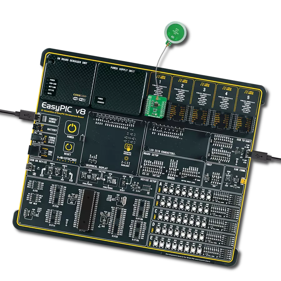
Circular NFC R25 Antenna is PCB antenna designed with the intention to be used as extension of development boards and placed remotely on desired place such as plastic casing, existing products, or even under displays. Antenna is designed in circular shape with diameter of 25mm. Its important to mention that this antenna can be used for NFC and RFID applications that works on 13.56MHz frequency.
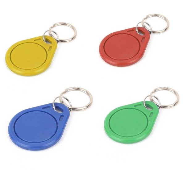
RFID tag operating at 13.56MHz adheres to the ISO14443-A standard, ensuring high-frequency communication. This proximity card technology, often exemplified by MIFARE cards, facilitates secure and contactless interactions in applications like access control, public transport, and payment systems. The ISO14443-A standard defines the communication protocol, incorporating anti-collision mechanisms for simultaneous card handling. These RFID tags possess variable memory capacities, ranging from a few bytes to kilobytes, catering to diverse application needs. Ensuring data security, the standard integrates features such as encryption and authentication. These tags, exemplified by MIFARE technology, are widely used for their efficiency and are vital in enhancing convenience and security in diverse identification and access scenarios.
Used MCU Pins
mikroBUS™ mapper
Take a closer look
Click board™ Schematic

Step by step
Project assembly

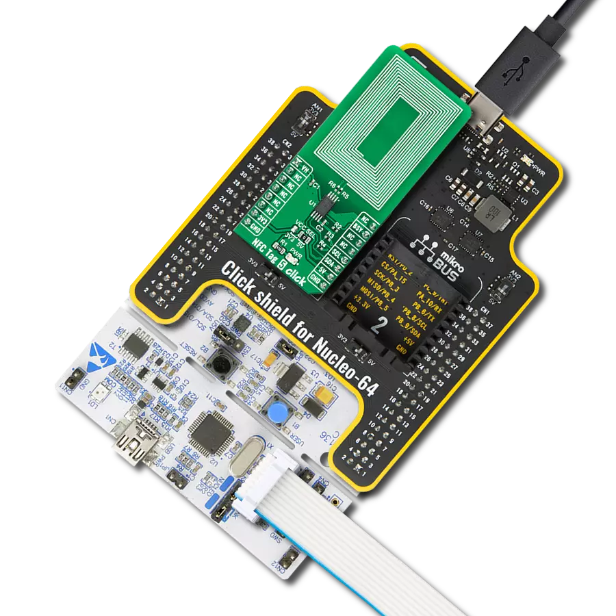
Start by selecting your development board and Click board™. Begin with the CLICKER 4 for STM32F302VCT6 as your development board.


Software Support
Library Description
Smart NFC Click demo application is developed using the NECTO Studio, ensuring compatibility with mikroSDK's open-source libraries and tools. Designed for plug-and-play implementation and testing, the demo is fully compatible with all development, starter, and mikromedia boards featuring a mikroBUS™ socket.
Example Description
This example demonstrates the use of the Smart NFC Click board for detecting and reading NFC tags. The application resets the NFC module, retrieves the firmware version, and continuously scans for nearby NFC tags, displaying their UID and type.
Key functions:
smartnfc_cfg_setup- This function initializes Click configuration structure to initial values.smartnfc_init- This function initializes all necessary pins and peripherals used for this Click board.smartnfc_send_frame- This function sends a desired command frame from the Click context object.smartnfc_read_frame- This function reads response frame from the ring buffer and stores it in the Click context object.smartnfc_read_ack_frame- This function waits for the desired acknowledge frame to arrive and stores it in the Click context object.
Application Init
Initializes the logger and configures the Smart NFC Click board. It establishes UART communication, resets the NFC module, and retrieves the firmware version to verify proper operation.
Application Task
Continuously scans for NFC tags and retrieves their unique identifiers (UID). If tags are detected, it logs their type, parameters, and UID values. The process repeats at 1-second intervals.
Open Source
Code example
The complete application code and a ready-to-use project are available through the NECTO Studio Package Manager for direct installation in the NECTO Studio. The application code can also be found on the MIKROE GitHub account.
/*!
 * @file main.c
 * @brief Smart NFC Click Example.
 *
 * # Description
 * This example demonstrates the use of the Smart NFC Click board for detecting and
 * reading NFC tags. The application resets the NFC module, retrieves the firmware
 * version, and continuously scans for nearby NFC tags, displaying their UID and type.
 *
 * The demo application is composed of two sections:
 *
 * ## Application Init
 * Initializes the logger and configures the Smart NFC Click board. It establishes
 * UART communication, resets the NFC module, and retrieves the firmware version
 * to verify proper operation.
 *
 * ## Application Task
 * Continuously scans for NFC tags and retrieves their unique identifiers (UID).
 * If tags are detected, it logs their type, parameters, and UID values. The process
 * repeats at 1-second intervals.
 *
 * @note
 * A proper 13.56 MHz PCB NFC antenna must be attached to the Click board module
 * for optimal tag detection.
 *
 * @author Stefan Filipovic
 *
 */

#include "board.h"
#include "log.h"
#include "smartnfc.h"

static smartnfc_t smartnfc;
static log_t logger;

void application_init ( void )
{
    log_cfg_t log_cfg;  /**< Logger config object. */
    smartnfc_cfg_t smartnfc_cfg;  /**< Click config object. */

    /**
     * Logger initialization.
     * Default baud rate: 115200
     * Default log level: LOG_LEVEL_DEBUG
     * @note If USB_UART_RX and USB_UART_TX
     * are defined as HAL_PIN_NC, you will
     * need to define them manually for log to work.
     * See @b LOG_MAP_USB_UART macro definition for detailed explanation.
     */
    LOG_MAP_USB_UART( log_cfg );
    log_init( &logger, &log_cfg );
    log_info( &logger, " Application Init " );

    // Click initialization.
    smartnfc_cfg_setup( &smartnfc_cfg );
    SMARTNFC_MAP_MIKROBUS( smartnfc_cfg, MIKROBUS_1 );
    if ( UART_ERROR == smartnfc_init( &smartnfc, &smartnfc_cfg ) )
    {
        log_error( &logger, " Communication init." );
        for ( ; ; );
    }

    log_printf( &logger, ">> Reset Device\r\n" );
    if ( SMARTNFC_OK == smartnfc_reset_device ( &smartnfc ) )
    {
        log_printf( &logger, "--------------------------------\r\n" );
    }

    log_printf( &logger, ">> Get Version\r\n" );
    smartnfc.cmd_frame.cmd = SMARTNFC_CMD_GET_VERSION;
    smartnfc.cmd_frame.payload_len = 0;
    smartnfc_send_frame ( &smartnfc );
    if ( SMARTNFC_OK == smartnfc_read_ack_frame ( &smartnfc, SMARTNFC_CMD_GET_VERSION ) )
    {
        log_printf ( &logger, "%s\r\n", &smartnfc.rsp_frame.payload[ 1 ] );
        log_printf( &logger, "--------------------------------\r\n" );
    }

    log_info( &logger, " Application Task " );
}

void application_task ( void )
{
    uint8_t num_tags_found = 0;
    log_printf( &logger, ">> Get Tag Count\r\n" );
    smartnfc.cmd_frame.cmd = SMARTNFC_CMD_GET_TAG_COUNT;
    smartnfc.cmd_frame.payload_len = 0;
    smartnfc_send_frame ( &smartnfc );
    if ( SMARTNFC_OK == smartnfc_read_ack_frame ( &smartnfc, SMARTNFC_CMD_GET_TAG_COUNT ) )
    {
        log_printf ( &logger, "Number of tags found: %u\r\n", ( uint16_t ) smartnfc.rsp_frame.payload[ 1 ] );
        log_printf( &logger, "--------------------------------\r\n" );
        num_tags_found = smartnfc.rsp_frame.payload[ 1 ];
        for ( uint8_t tag_idx = 0; tag_idx < num_tags_found; tag_idx++ )
        {
            log_printf( &logger, ">> Get Tag UID\r\n" );
            smartnfc.cmd_frame.cmd = SMARTNFC_CMD_GET_TAG_UID;
            smartnfc.cmd_frame.payload[ 0 ] = tag_idx;
            smartnfc.cmd_frame.payload_len = 1;
            smartnfc_send_frame ( &smartnfc );
            if ( SMARTNFC_OK == smartnfc_read_ack_frame ( &smartnfc, SMARTNFC_CMD_GET_TAG_UID ) )
            {
                log_printf ( &logger, "Tag Type: 0x%.2X\r\n", ( uint16_t ) smartnfc.rsp_frame.payload[ 1 ] );
                log_printf ( &logger, "Tag Parameter: 0x%.2X\r\n", ( uint16_t ) smartnfc.rsp_frame.payload[ 2 ] );
                log_printf ( &logger, "UID:" );
                for ( uint8_t cnt_uid = 0; cnt_uid < ( smartnfc.rsp_frame.payload_len - 3 ); cnt_uid++ )
                {
                    log_printf ( &logger, " %.2X", ( uint16_t ) smartnfc.rsp_frame.payload[ 3 + cnt_uid ] );
                }
                log_printf( &logger, "\r\n--------------------------------\r\n" );
            }
        }
    }
    Delay_ms ( 1000 );
}

int main ( void )
{
    /* Do not remove this line or clock might not be set correctly. */
    #ifdef PREINIT_SUPPORTED
    preinit();
    #endif

    application_init( );

    for ( ; ; )
    {
        application_task( );
    }

    return 0;
}

// ------------------------------------------------------------------------ END
Additional Support
Resources
Category:RFID/NFC