Achieve control of high-power two-phase bipolar stepper motors with the A4989SLD and STM32G474RE
High-power, precise stepper motor control solution for industrial applications
Published Jul 14, 2025
Click board™
Power Step Click
Dev. board
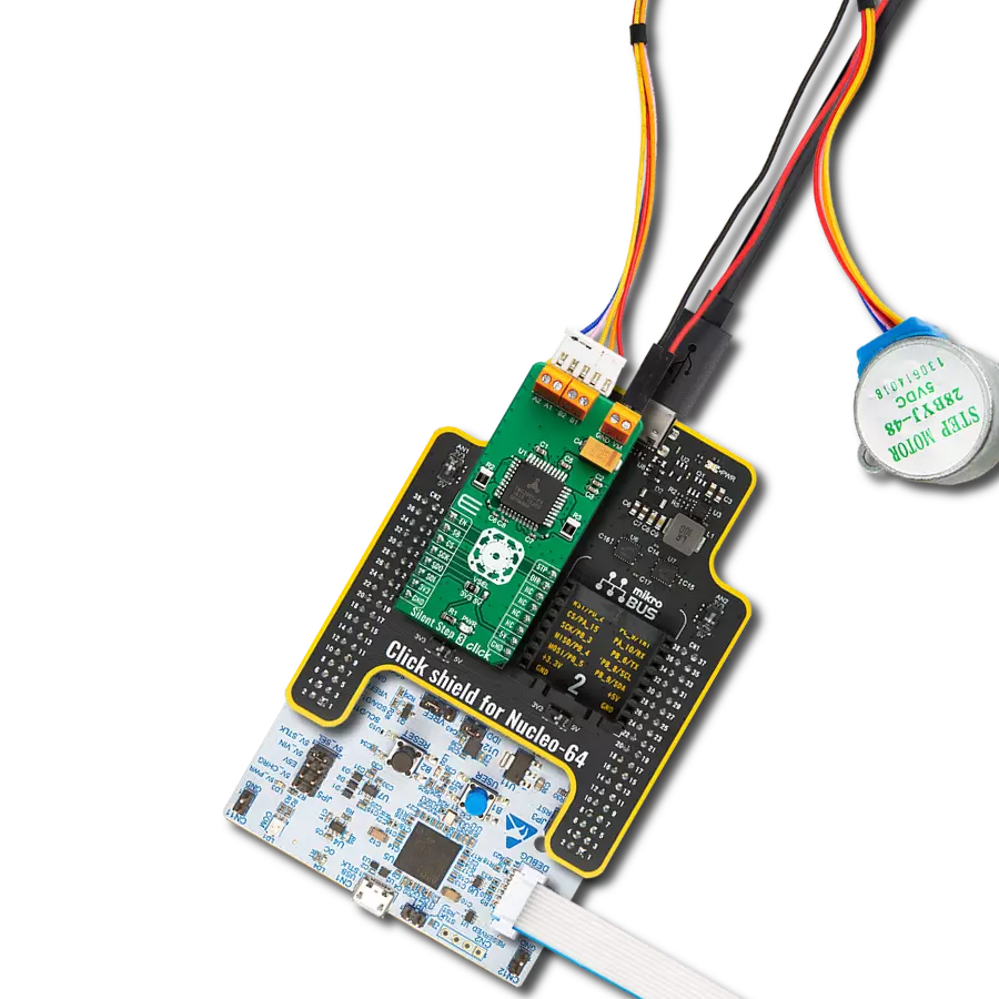
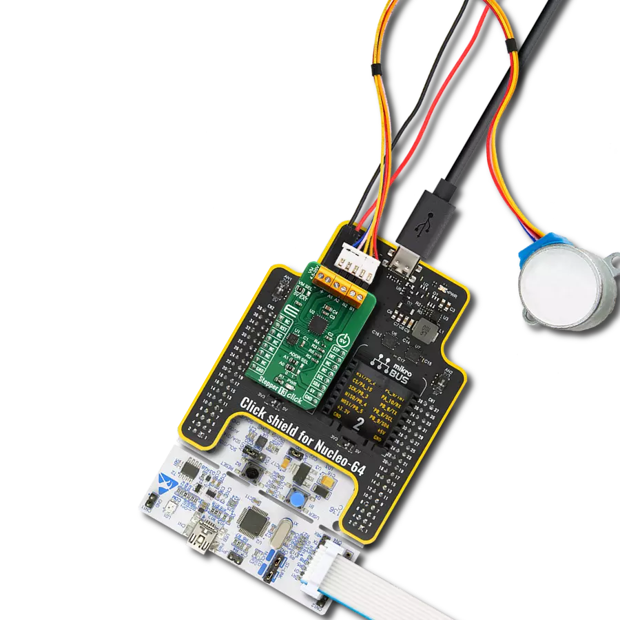
Nucleo 64 with STM32G474RE MCU
Compiler
NECTO Studio
MCU
STM32G474RE
Your go-to solution for driving robust stepper motors in challenging industrial environments
A
A
Hardware Overview
How does it work?
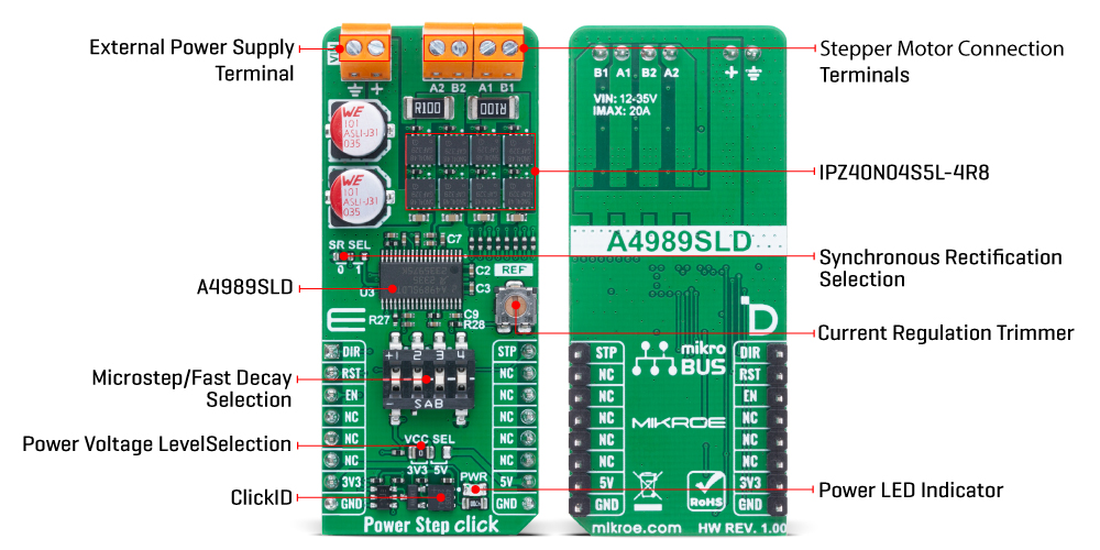
Power Step Click is based on the A4989SLD, a dual full-bridge MOSFET driver with a microstepping translator from Allegro Microsystems. Designed to control higher power industrial two-phase stepper motors typically ranging from 30 to 500 watts, this board uses eight external N-channel power MOSFETs (IPZ40N04S5L-4R8) to deliver motor currents up to 20A at operating voltages between 12 and 35V on the VIN terminal. At the core of the Power Step Click, the A4989SLD features two sinusoidal DACs that serve as reference voltage generators for two individual fixed off-time PWM current controllers, ensuring precise current regulation across both full-bridge driver outputs. In addition to the internal DACs, the board includes a REF trimmer that allows users to manually set the reference voltage for current regulation, providing an extra layer of flexibility when fine-tuning the motor current according to specific application requirements. The Power Step Click is an ideal solution for engineers seeking a robust and flexible stepper motor driver platform that minimizes control complexity while offering high power performance. The board is equipped with a simple two-wire control interface - step and direction (STP and DIR) - enabling microstepping control at selectable resolutions of
full, half, quarter, and sixteenth steps, configured via combination of multifunctional switch pins 3 and 4. The internal translator logic of the A4989SLD simplifies implementation by eliminating the need for high-frequency control signals or complex phase-sequencing, as each input pulse on the STP pin directly advances the motor by one step at the chosen resolution. Additionally, the driver supports multiple decay modes - slow, mixed, and fast - which can be created using multifunctional switch pins 1 and 2 to select the proportion of fast decay when mixed decay is active. This intelligent decay mode configuration contributes to quieter operation, improved step accuracy, and lower overall power dissipation. In addition to the STP pin used for stepping control, Power Step Click incorporates several other control inputs to enhance the flexibility and performance. The DIR pin functions as the direction input, determining the rotational direction of the motor - when held LOW, the motor rotates clockwise, and when held HIGH, it rotates counter-clockwise. Importantly, any change in the DIR pin state takes effect only on the rising edge of the next pulse on the STP pin, ensuring accurate directional control synchronized with the stepping logic. The board also includes an RST pin that serves to reset the A4989SLD IC, returning it to a
known default state when triggered, as well as an EN pin that acts as an output enable signal. When the EN pin is asserted, the power output stages are activated, allowing motor control; when deasserted, all outputs are disabled, putting the system into a low-power or idle state. Additionally, Power Step Click features a jumper labeled SR SEL, which is used to set the behavior of the synchronous rectification feature. When the SR SEL jumper is in position 0 (active mode), the device actively prevents current reversal by disabling synchronous rectification once a zero-current condition is detected, thus stopping the motor windings from conducting in the reverse direction. This mode is optimal for reducing power dissipation through the MOSFETs while maintaining precise current control. Alternatively, when SR SEL is set to position 1 (disabled mode), synchronous rectification is turned off entirely. This Click board™ can operate with either 3.3V or 5V logic voltage levels selected via the VCC SEL jumper. This way, both 3.3V and 5V capable MCUs can use the communication lines properly. Also, this Click board™ comes equipped with a library containing easy-to-use functions and an example code that can be used as a reference for further development.
Features overview
Development board
Nucleo-64 with STM32G474R MCU offers a cost-effective and adaptable platform for developers to explore new ideas and prototype their designs. This board harnesses the versatility of the STM32 microcontroller, enabling users to select the optimal balance of performance and power consumption for their projects. It accommodates the STM32 microcontroller in the LQFP64 package and includes essential components such as a user LED, which doubles as an ARDUINO® signal, alongside user and reset push-buttons, and a 32.768kHz crystal oscillator for precise timing operations. Designed with expansion and flexibility in mind, the Nucleo-64 board features an ARDUINO® Uno V3 expansion connector and ST morpho extension pin
headers, granting complete access to the STM32's I/Os for comprehensive project integration. Power supply options are adaptable, supporting ST-LINK USB VBUS or external power sources, ensuring adaptability in various development environments. The board also has an on-board ST-LINK debugger/programmer with USB re-enumeration capability, simplifying the programming and debugging process. Moreover, the board is designed to simplify advanced development with its external SMPS for efficient Vcore logic supply, support for USB Device full speed or USB SNK/UFP full speed, and built-in cryptographic features, enhancing both the power efficiency and security of projects. Additional connectivity is
provided through dedicated connectors for external SMPS experimentation, a USB connector for the ST-LINK, and a MIPI® debug connector, expanding the possibilities for hardware interfacing and experimentation. Developers will find extensive support through comprehensive free software libraries and examples, courtesy of the STM32Cube MCU Package. This, combined with compatibility with a wide array of Integrated Development Environments (IDEs), including IAR Embedded Workbench®, MDK-ARM, and STM32CubeIDE, ensures a smooth and efficient development experience, allowing users to fully leverage the capabilities of the Nucleo-64 board in their projects.

Microcontroller Overview
MCU Card / MCU

Architecture
ARM Cortex-M4
MCU Memory (KB)
512
Silicon Vendor
STMicroelectronics
Pin count
64
RAM (Bytes)
128k
You complete me!
Accessories
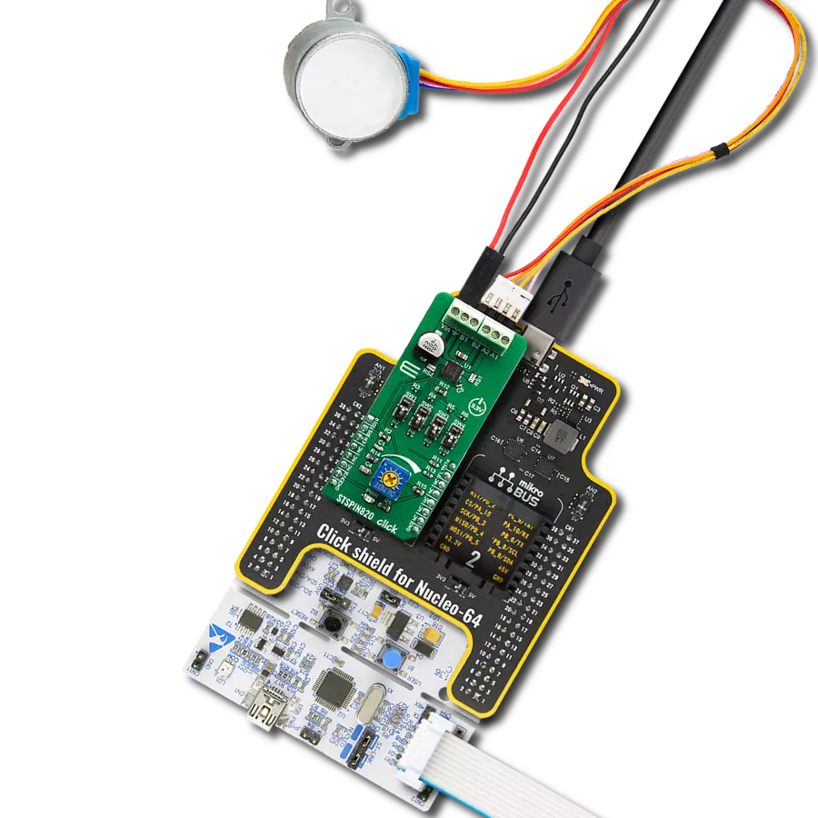
Click Shield for Nucleo-64 comes equipped with two proprietary mikroBUS™ sockets, allowing all the Click board™ devices to be interfaced with the STM32 Nucleo-64 board with no effort. This way, Mikroe allows its users to add any functionality from our ever-growing range of Click boards™, such as WiFi, GSM, GPS, Bluetooth, ZigBee, environmental sensors, LEDs, speech recognition, motor control, movement sensors, and many more. More than 1537 Click boards™, which can be stacked and integrated, are at your disposal. The STM32 Nucleo-64 boards are based on the microcontrollers in 64-pin packages, a 32-bit MCU with an ARM Cortex M4 processor operating at 84MHz, 512Kb Flash, and 96KB SRAM, divided into two regions where the top section represents the ST-Link/V2 debugger and programmer while the bottom section of the board is an actual development board. These boards are controlled and powered conveniently through a USB connection to program and efficiently debug the Nucleo-64 board out of the box, with an additional USB cable connected to the USB mini port on the board. Most of the STM32 microcontroller pins are brought to the IO pins on the left and right edge of the board, which are then connected to two existing mikroBUS™ sockets. This Click Shield also has several switches that perform functions such as selecting the logic levels of analog signals on mikroBUS™ sockets and selecting logic voltage levels of the mikroBUS™ sockets themselves. Besides, the user is offered the possibility of using any Click board™ with the help of existing bidirectional level-shifting voltage translators, regardless of whether the Click board™ operates at a 3.3V or 5V logic voltage level. Once you connect the STM32 Nucleo-64 board with our Click Shield for Nucleo-64, you can access hundreds of Click boards™, working with 3.3V or 5V logic voltage levels.

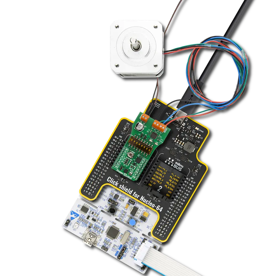
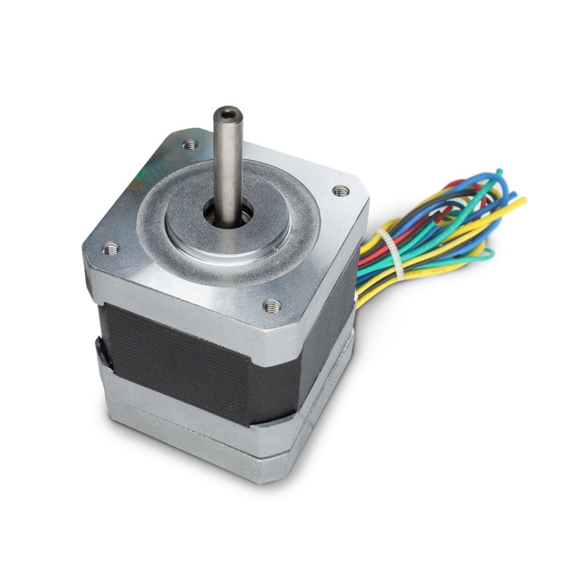
The 17HD40005-22B stepper motor is a two-phase hybrid motor for high torque, high speed, and low noise performance. It features a 1m wire with optional ports on the connection end and heat shrink tubing to prevent tangling. The motor's D-shaped axle is 22mm in length. This motor operates with a chopping wave constant current drive and has a two-phase 4-wire exciting mode, allowing for both forward and reverse rotation. The power order follows AB-BC-CD-DA, viewed as clockwise from the shaft end. It has a rated current of 1.3A DC, a rated voltage of 2.4V, and a stepping angle of 1.8°, with an insulation grade of B. This stepper motor is ideal for applications requiring precise movement control and reliability.
Used MCU Pins
mikroBUS™ mapper
Take a closer look
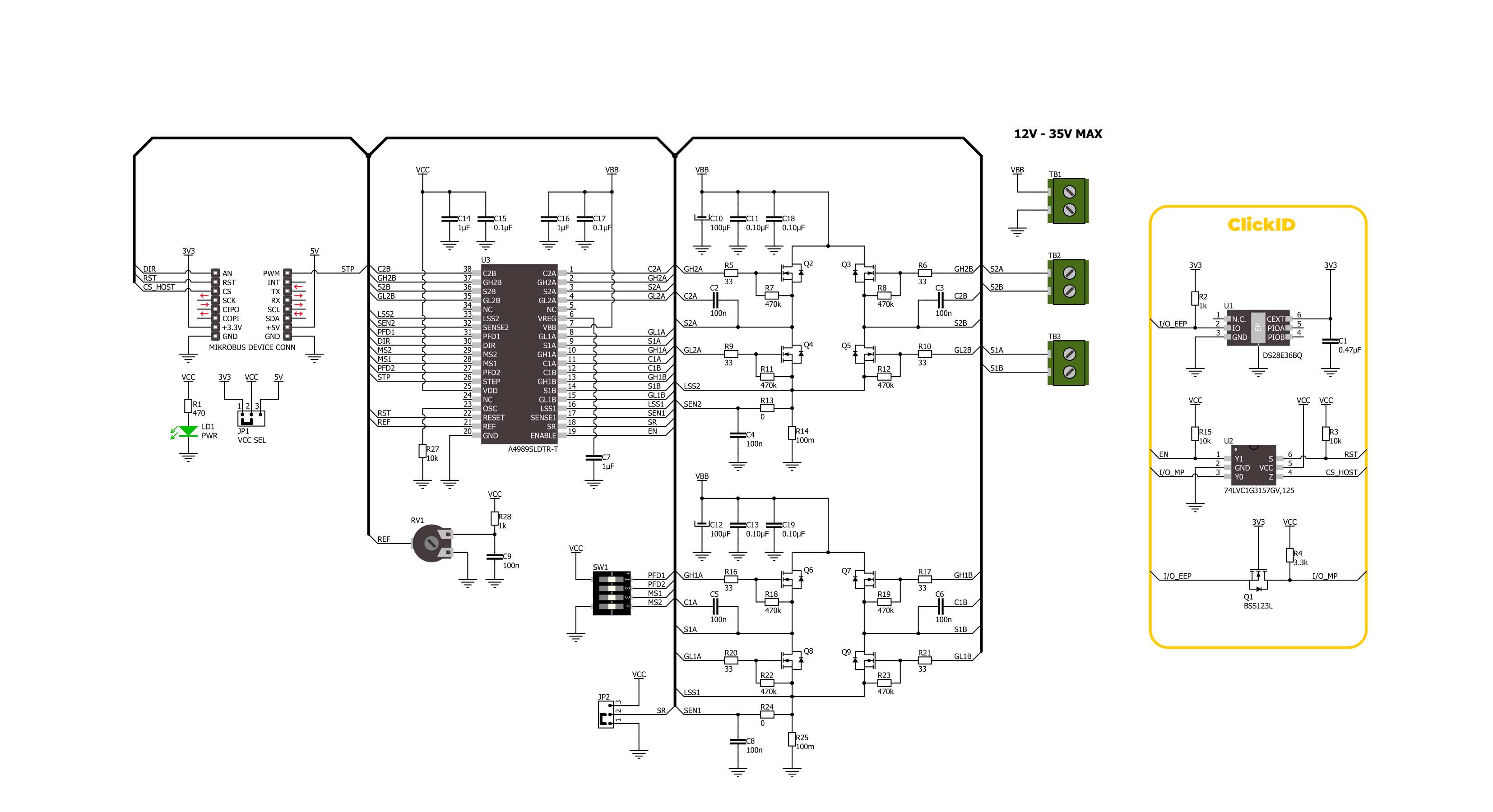
Click board™ Schematic
Step by step
Project assembly
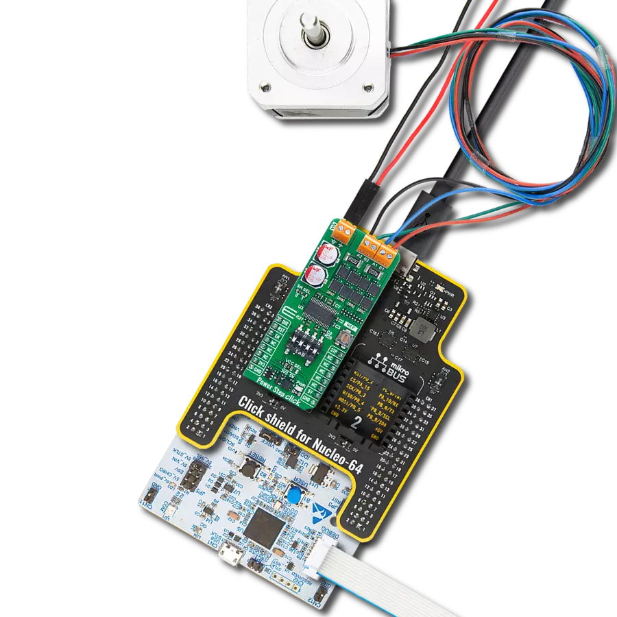
Start by selecting your development board and Click board™. Begin with the Nucleo 64 with STM32G474RE MCU as your development board.


Software Support
Library Description
Power Step Click demo application is developed using the NECTO Studio, ensuring compatibility with mikroSDK's open-source libraries and tools. Designed for plug-and-play implementation and testing, the demo is fully compatible with all development, starter, and mikromedia boards featuring a mikroBUS™ socket.
Example Description
This example demonstrates the use of the Power Step Click board by driving the motor in both directions for a desired number of steps.
Key functions:
powerstep_cfg_setup- This function initializes Click configuration structure to initial values.powerstep_init- This function initializes all necessary pins and peripherals used for this Click board.powerstep_reset_device- This function resets the device by setting the RST pin logic state.powerstep_drive_motor- This function drives the motor for the specific number of steps at the selected speed.
Application Init
Initializes the driver and resets the device.
Application Task
Drives the motor clockwise for 100 slow steps and 300 medium speed steps and then counter-clockwise for 400 fast steps with a 1 second delay on driving mode change. All data is being logged on the USB UART where you can track the program flow.
Open Source
Code example
The complete application code and a ready-to-use project are available through the NECTO Studio Package Manager for direct installation in the NECTO Studio. The application code can also be found on the MIKROE GitHub account.
/*!
 * @file main.c
 * @brief Power Step Click Example.
 *
 * # Description
 * This example demonstrates the use of the Power Step Click board by driving the
 * motor in both directions for a desired number of steps.
 *
 * The demo application is composed of two sections :
 *
 * ## Application Init
 * Initializes the driver and resets the device.
 *
 * ## Application Task
 * Drives the motor clockwise for 100 slow steps and 300 medium speed steps and
 * then counter-clockwise for 400 fast steps with a 1 second delay on driving mode change.
 * All data is being logged on the USB UART where you can track the program flow.
 *
 * @author Stefan Filipovic
 *
 */

#include "board.h"
#include "log.h"
#include "powerstep.h"

static powerstep_t powerstep;
static log_t logger;

void application_init ( void )
{
    log_cfg_t log_cfg;  /**< Logger config object. */
    powerstep_cfg_t powerstep_cfg;  /**< Click config object. */

    /**
     * Logger initialization.
     * Default baud rate: 115200
     * Default log level: LOG_LEVEL_DEBUG
     * @note If USB_UART_RX and USB_UART_TX
     * are defined as HAL_PIN_NC, you will
     * need to define them manually for log to work.
     * See @b LOG_MAP_USB_UART macro definition for detailed explanation.
     */
    LOG_MAP_USB_UART( log_cfg );
    log_init( &logger, &log_cfg );
    log_info( &logger, " Application Init " );

    // Click initialization.
    powerstep_cfg_setup( &powerstep_cfg );
    POWERSTEP_MAP_MIKROBUS( powerstep_cfg, MIKROBUS_1 );
    if ( DIGITAL_OUT_UNSUPPORTED_PIN == powerstep_init( &powerstep, &powerstep_cfg ) )
    {
        log_error( &logger, " Communication init." );
        for ( ; ; );
    }

    powerstep_reset_device ( &powerstep );

    log_info( &logger, " Application Task " );
}

void application_task ( void )
{
    log_printf ( &logger, " Move 100 steps clockwise, speed: slow\r\n\n" );
    powerstep_set_direction ( &powerstep, POWERSTEP_DIR_CW );
    powerstep_drive_motor ( &powerstep, 100, POWERSTEP_SPEED_SLOW );
    Delay_ms ( 1000 );

    log_printf ( &logger, " Move 300 steps clockwise, speed: medium\r\n\n" );
    powerstep_set_direction ( &powerstep, POWERSTEP_DIR_CW );
    powerstep_drive_motor ( &powerstep, 300, POWERSTEP_SPEED_MEDIUM );
    Delay_ms ( 1000 );

    log_printf ( &logger, " Move 400 steps counter-clockwise, speed: fast\r\n\n" );
    powerstep_set_direction ( &powerstep, POWERSTEP_DIR_CCW );
    powerstep_drive_motor ( &powerstep, 400, POWERSTEP_SPEED_FAST );
    Delay_ms ( 1000 );
}

int main ( void )
{
    /* Do not remove this line or clock might not be set correctly. */
    #ifdef PREINIT_SUPPORTED
    preinit();
    #endif

    application_init( );

    for ( ; ; )
    {
        application_task( );
    }

    return 0;
}

// ------------------------------------------------------------------------ END
Additional Support
Resources
Category:Stepper