Get precise absolute pressure measurement with KP226E3408 and STM32G474RE
Absolute pressure sensing solution for automotive, industrial, and consumer applications
Published Aug 28, 2025
Click board™
Barometer 11 Click
Dev. board
Nucleo 64 with STM32G474RE MCU
Compiler
NECTO Studio
MCU
STM32G474RE
Achieve absolute pressure measurement with high accuracy and flexible output options for demanding environments
A
A
Hardware Overview
How does it work?
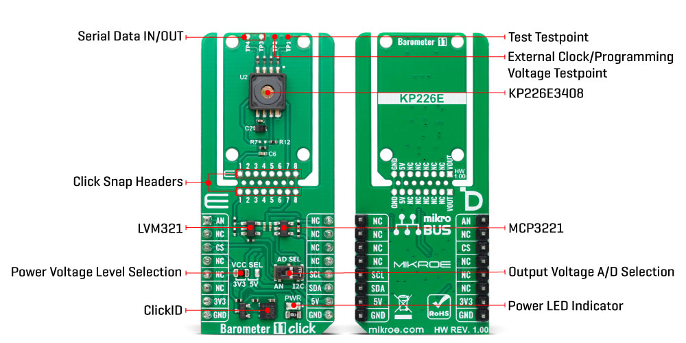
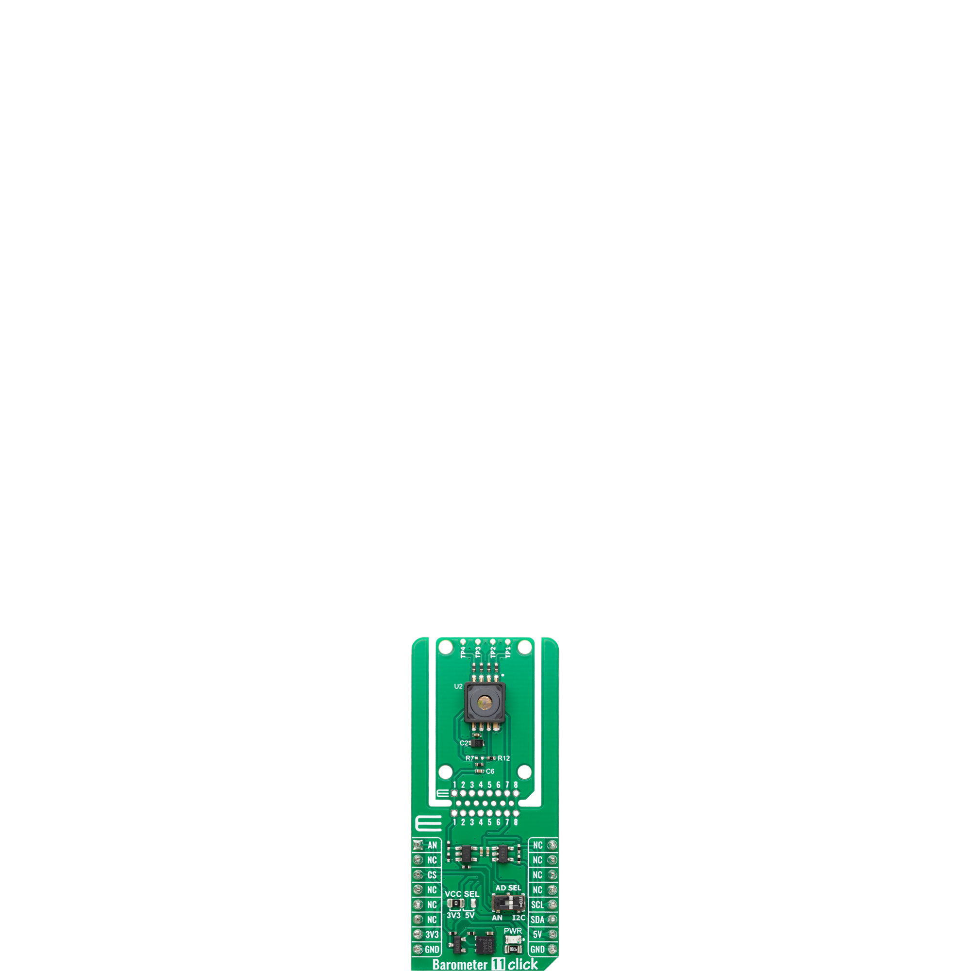
Barometer 11 Click is based on the KP226E3408, an analog absolute pressure sensor from Infineon, which operates on a capacitive measurement principle and integrates a monolithic signal conditioning circuit using BiCMOS technology. The device converts applied pressure directly into a highly precise analog voltage output, with a calibrated transfer function that maps pressures from 15kPa to 400kPa into a corresponding output range of 0.35V to 4.65V. With a high-accuracy pressure measurement capability of ±3.8kPa and excellent sensitivity, the sensor ensures reliable performance in applications requiring precise environmental or process monitoring. Designed to function in harsh conditions, it supports an extended operating temperature range from -40°C to 140°C, enabling use in diverse environments. While primarily intended for automotive manifold absolute pressure measurement, its versatile performance characteristics make it equally suitable for various industrial automation, environmental sensing, and consumer product implementations where stable, accurate pressure data is essential. This Click board™ is designed in a unique format supporting the newly introduced MIKROE feature called "Click Snap." Unlike the standardized version of Click boards, this feature allows the main sensor/IC/module area to become movable by breaking the PCB, opening up many
new possibilities for implementation. Thanks to the Snap feature, the BQ25188 can operate autonomously by accessing its signals directly on the pins marked 1-8. Additionally, the Snap part includes a specified and fixed screw hole position, enabling users to secure the Snap board in their desired location. The signal conditioning and amplification for the KP226E3408 sensor are handled by the LMV321, a low-voltage rail-to-rail operational amplifier from Texas Instruments, ensuring precise and stable amplification of the sensor's low-level output signal. After amplification, the conditioned signal is routed to the AD SEL switch, providing the user with the flexibility to choose between analog and digital output modes depending on the specific requirements of their application. When analog output is selected, the amplified signal is made available directly on the AN pin of the mikroBUS™ socket, allowing for straightforward integration with analog signal processing circuits. For digital signal acquisition, the board incorporates the MCP3221 from Microchip, a 12-bit resolution analog-to-digital converter that enables high-accuracy digital conversion and communicates via the standard 2-wire I2C interface, ensuring compatibility with a wide range of MCUs and digital systems. The output mode selection is easily configured through the onboard surface-mount device (SMD) switch
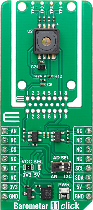
labeled AD SEL, which allows users to toggle between the analog (AN) position and the digital (I2C) position to accommodate diverse application scenarios and design preferences. At the very top of the Snap section, four test points are positioned to provide direct access for measurement, communication, and programming operations with the onboard sensor. TP1 carries the sensor’s test signal, enabling verification and diagnostics of its operational performance. TP2 provides the external clock input used for communication or delivers the programming voltage signal required during sensor configuration and calibration. TP3 and TP4 serve as the serial data input and output pins of the sensor, forming the core of its test and programming interface. This layout allows engineers to easily connect diagnostic tools, external programmers, or development equipment to monitor signals, apply configuration parameters, and conduct functional testing without interfering with the standard operational circuitry. This Click board™ can operate with either 3.3V or 5V logic voltage levels selected via the VCC SEL jumper. This way, both 3.3V and 5V capable MCUs can use the communication lines properly. Also, this Click board™ comes equipped with a library containing easy-to-use functions and an example code that can be used as a reference for further development.
Features overview
Development board
Nucleo-64 with STM32G474R MCU offers a cost-effective and adaptable platform for developers to explore new ideas and prototype their designs. This board harnesses the versatility of the STM32 microcontroller, enabling users to select the optimal balance of performance and power consumption for their projects. It accommodates the STM32 microcontroller in the LQFP64 package and includes essential components such as a user LED, which doubles as an ARDUINO® signal, alongside user and reset push-buttons, and a 32.768kHz crystal oscillator for precise timing operations. Designed with expansion and flexibility in mind, the Nucleo-64 board features an ARDUINO® Uno V3 expansion connector and ST morpho extension pin
headers, granting complete access to the STM32's I/Os for comprehensive project integration. Power supply options are adaptable, supporting ST-LINK USB VBUS or external power sources, ensuring adaptability in various development environments. The board also has an on-board ST-LINK debugger/programmer with USB re-enumeration capability, simplifying the programming and debugging process. Moreover, the board is designed to simplify advanced development with its external SMPS for efficient Vcore logic supply, support for USB Device full speed or USB SNK/UFP full speed, and built-in cryptographic features, enhancing both the power efficiency and security of projects. Additional connectivity is
provided through dedicated connectors for external SMPS experimentation, a USB connector for the ST-LINK, and a MIPI® debug connector, expanding the possibilities for hardware interfacing and experimentation. Developers will find extensive support through comprehensive free software libraries and examples, courtesy of the STM32Cube MCU Package. This, combined with compatibility with a wide array of Integrated Development Environments (IDEs), including IAR Embedded Workbench®, MDK-ARM, and STM32CubeIDE, ensures a smooth and efficient development experience, allowing users to fully leverage the capabilities of the Nucleo-64 board in their projects.

Microcontroller Overview
MCU Card / MCU

Architecture
ARM Cortex-M4
MCU Memory (KB)
512
Silicon Vendor
STMicroelectronics
Pin count
64
RAM (Bytes)
128k
You complete me!
Accessories
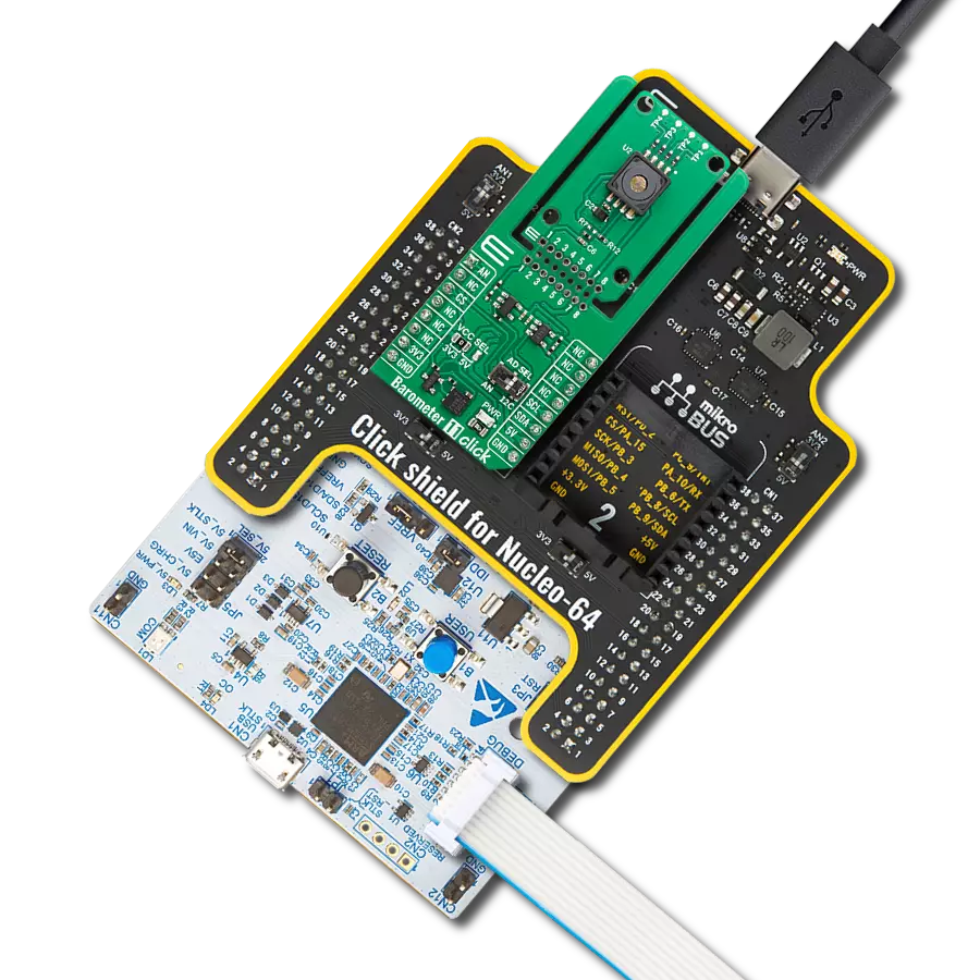
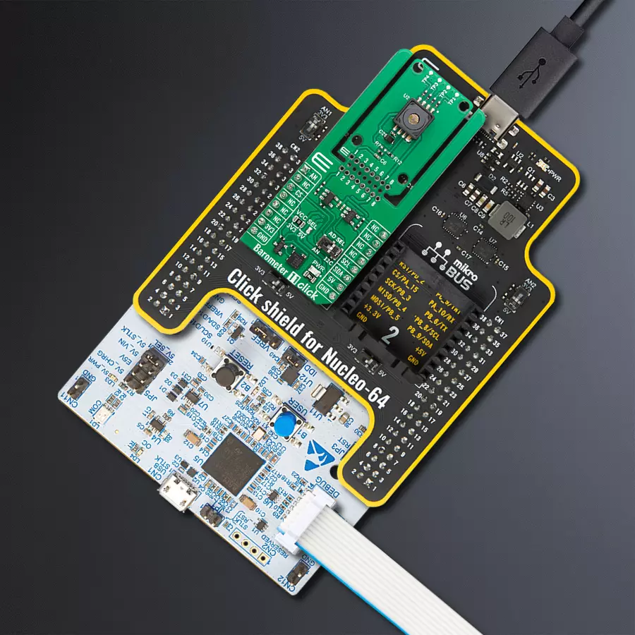
Click Shield for Nucleo-64 comes equipped with two proprietary mikroBUS™ sockets, allowing all the Click board™ devices to be interfaced with the STM32 Nucleo-64 board with no effort. This way, Mikroe allows its users to add any functionality from our ever-growing range of Click boards™, such as WiFi, GSM, GPS, Bluetooth, ZigBee, environmental sensors, LEDs, speech recognition, motor control, movement sensors, and many more. More than 1537 Click boards™, which can be stacked and integrated, are at your disposal. The STM32 Nucleo-64 boards are based on the microcontrollers in 64-pin packages, a 32-bit MCU with an ARM Cortex M4 processor operating at 84MHz, 512Kb Flash, and 96KB SRAM, divided into two regions where the top section represents the ST-Link/V2 debugger and programmer while the bottom section of the board is an actual development board. These boards are controlled and powered conveniently through a USB connection to program and efficiently debug the Nucleo-64 board out of the box, with an additional USB cable connected to the USB mini port on the board. Most of the STM32 microcontroller pins are brought to the IO pins on the left and right edge of the board, which are then connected to two existing mikroBUS™ sockets. This Click Shield also has several switches that perform functions such as selecting the logic levels of analog signals on mikroBUS™ sockets and selecting logic voltage levels of the mikroBUS™ sockets themselves. Besides, the user is offered the possibility of using any Click board™ with the help of existing bidirectional level-shifting voltage translators, regardless of whether the Click board™ operates at a 3.3V or 5V logic voltage level. Once you connect the STM32 Nucleo-64 board with our Click Shield for Nucleo-64, you can access hundreds of Click boards™, working with 3.3V or 5V logic voltage levels.

Used MCU Pins
mikroBUS™ mapper
Take a closer look
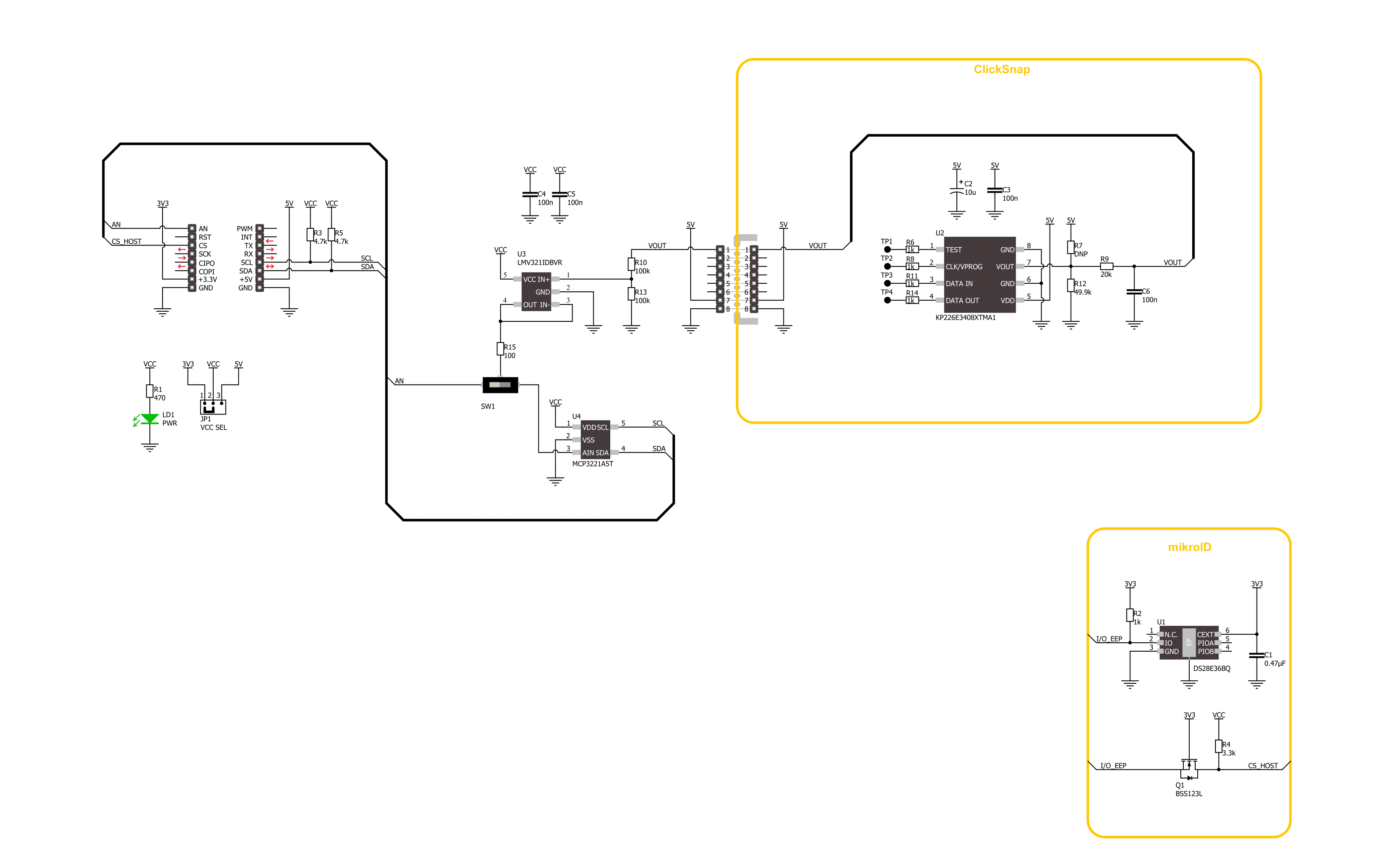
Click board™ Schematic
Step by step
Project assembly
Start by selecting your development board and Click board™. Begin with the Nucleo 64 with STM32G474RE MCU as your development board.


Track your results in real time
Application Output
1. Application Output - In Debug mode, the 'Application Output' window enables real-time data monitoring, offering direct insight into execution results. Ensure proper data display by configuring the environment correctly using the provided tutorial.

2. UART Terminal - Use the UART Terminal to monitor data transmission via a USB to UART converter, allowing direct communication between the Click board™ and your development system. Configure the baud rate and other serial settings according to your project's requirements to ensure proper functionality. For step-by-step setup instructions, refer to the provided tutorial.

3. Plot Output - The Plot feature offers a powerful way to visualize real-time sensor data, enabling trend analysis, debugging, and comparison of multiple data points. To set it up correctly, follow the provided tutorial, which includes a step-by-step example of using the Plot feature to display Click board™ readings. To use the Plot feature in your code, use the function: plot(*insert_graph_name*, variable_name);. This is a general format, and it is up to the user to replace 'insert_graph_name' with the actual graph name and 'variable_name' with the parameter to be displayed.

Software Support
Library Description
Barometer 11 Click demo application is developed using the NECTO Studio, ensuring compatibility with mikroSDK's open-source libraries and tools. Designed for plug-and-play implementation and testing, the demo is fully compatible with all development, starter, and mikromedia boards featuring a mikroBUS™ socket.
Example Description
This example demonstrates the use of the Barometer 11 Click board by initializing the device and reading the barometric pressure data in millibar units. The pressure value is periodically logged to the USB UART every second.
Key functions:
barometer11_cfg_setup- This function initializes Click configuration structure to initial values.barometer11_init- This function initializes all necessary pins and peripherals used for this Click board.barometer11_read_voltage_avg- This function reads a desired number of ADC samples and calculates the average voltage level.barometer11_read_pressure- This function reads the pressure level [mBar].
Application Init
Initializes the logger and the Barometer 11 Click driver.
Application Task
Reads and displays the pressure data every second.
Open Source
Code example
The complete application code and a ready-to-use project are available through the NECTO Studio Package Manager for direct installation in the NECTO Studio. The application code can also be found on the MIKROE GitHub account.
/*!
 * @file main.c
 * @brief Barometer 11 Click Example.
 *
 * # Description
 * This example demonstrates the use of the Barometer 11 Click board by initializing
 * the device and reading the barometric pressure data in millibar units.
 * The pressure value is periodically logged to the USB UART every second.
 *
 * The demo application is composed of two sections:
 *
 * ## Application Init
 * Initializes the logger and the Barometer 11 Click driver.
 *
 * ## Application Task
 * Reads and displays the pressure data every second.
 *
 * @author Stefan Filipovic
 *
 */

#include "board.h"
#include "log.h"
#include "barometer11.h"

static barometer11_t barometer11;   /**< Barometer 11 Click driver object. */
static log_t logger;                /**< Logger object. */

void application_init ( void )
{
    log_cfg_t log_cfg;  /**< Logger config object. */
    barometer11_cfg_t barometer11_cfg;  /**< Click config object. */

    /**
     * Logger initialization.
     * Default baud rate: 115200
     * Default log level: LOG_LEVEL_DEBUG
     * @note If USB_UART_RX and USB_UART_TX
     * are defined as HAL_PIN_NC, you will
     * need to define them manually for log to work.
     * See @b LOG_MAP_USB_UART macro definition for detailed explanation.
     */
    LOG_MAP_USB_UART( log_cfg );
    log_init( &logger, &log_cfg );
    log_info( &logger, " Application Init " );

    // Click initialization.
    barometer11_cfg_setup( &barometer11_cfg );
    BAROMETER11_MAP_MIKROBUS( barometer11_cfg, MIKROBUS_1 );
    err_t init_flag = barometer11_init( &barometer11, &barometer11_cfg );
    if ( ( ADC_ERROR == init_flag ) || ( I2C_MASTER_ERROR == init_flag ) )
    {
        log_error( &logger, " Communication init." );
        for ( ; ; );
    }

    log_info( &logger, " Application Task " );
}

void application_task ( void )
{
    float pressure = 0;
    if ( BAROMETER11_OK == barometer11_read_pressure ( &barometer11, &pressure ) )
    {
        log_printf( &logger, " Pressure : %.1f mBar\r\n\n", pressure );
        Delay_ms ( 1000 );
    }
}

int main ( void )
{
    /* Do not remove this line or clock might not be set correctly. */
    #ifdef PREINIT_SUPPORTED
    preinit();
    #endif

    application_init( );

    for ( ; ; )
    {
        application_task( );
    }

    return 0;
}

// ------------------------------------------------------------------------ END
Additional Support
Resources
Category:Pressure


